Module 2. Entity–Relationship Data Model
(Hours: IT = 3 | Computer = 4)
(Marks: 15-25)
Syllabus:
- Introduction
- Benefits of Data Modeling
- Types of Models
- Phases of Database Modeling
- The Entity-Relationship (ER) Model
- Extended Entity-Relationship (EER) Model
- Generalization
- Specialization
- Aggregation
University Paper Questions and Answers
Introduction
Building a database system is a complex process that normally requires analyzing the user's requirements followed by a design process and finally concluding with an implementation. During analysis and design, the database designer normally needs to build a model of the proposed database system. Database modeling is essential to adequately manage the database development process.
Why Models?
Models have not been invented recently. Humans have used models for a long time for a variety of purposes and perhaps that is why modeling is interpreted differently by different people. Consider some examples of model building:
- Architects build models of buildings to show what a building or a house would look like. Landscape architects build models of landscaping to show what a landscape or garden will look like.
- Aeronautical engineers build models of planes to show what a plane would look like. Scaled models may also be used in testing to evaluate a plane's performance.
- Computer architects build models of new computers or new circuit boards that are implemented in hardware.
- Traffic engineers build models of traffic for a city or part of a city to show why there are traffic problems or how they could be solved.
The reader may think of other applications. Building models is common in science, engineering and computing.
A model is an abstract (and often incomplete) representation of the design or definition of a complex product, process or situation (for example, information requirements of an enterprise). Model is simplification of reality. |
A model need not be related to one particular situation; it may model a class of situations. For example, a database model may model all kinds of libraries but often each new situation requires a customized model. A model may describe, at different levels of abstraction, an organization of the elements of a product, process or situation.
Data Modeling
The role of data modeling in building database systems is similar to the role of an architect in building a substantial house or a building. In building a house, one does not just collect all the family members and draw some plans on a piece of paper and give it to a builder expecting it to lead to a well designed house that will meet the current and future needs of the family. Similarly, in building an enterprise database system one does not just collect all the users of the database and draw some plans on a piece of paper and give them to a database builder expecting it to lead to a well designed database system that will meet the current and future needs of the enterprise. Data modeling is therefore similar to the work of an architect whose job is to design a model that transforms the client's requirements into specifications which are then given to the database builder. Just like the architect does not disappear when the builder arrives, a database modeler also does not disappear when the database builder takes over. Both the architect and the database modeler have a role in supervising the building activity. Underlying the structure of a database is the data model.
A data model—a collection of concepts that can be used to describe the structure of a database. |
By structure of a database we mean the data types, relationships, and constraints that apply to the data. A data model provides a way to describe the design of a database at the physical, logical, and view levels.
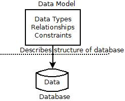
Figure: Data Model
Benefits of Data Modeling
As noted earlier, models are built for a variety of purposes. Database modeling is essential in building any nontrivial database system for assisting communication between the client and the database designer. Modeling has the following benefits:
- Focusing on essentials—Modeling often leads to developing an abstract and simple view of the product or process that is the subject of modeling. It is thus possible to ignore the details that tend to distract from the essential features. For example, when modeling a library we need to focus on the essential features, e.g., borrowers, books, serials, and at least in the beginning it may be possible to ignore that there are a variety of books (for example, some may have several editions) and serials (for example, some are published monthly while others quarterly and so on).
- Ease of communication and understanding—Model building formalizes the process of reliable communication and assists in reaching an agreement. Model building therefore helps all parties involved in building a model to reach a common understanding of the subject of modeling, given that modeling formalizes communication. Communication during modeling also involves developing documentation describing what is being modeled. A model may be expressed in text or in a graphical language or it may even be more concrete like a prototype. A suitable expression medium should be chosen to assist communication. Designing a good library system would require suitable communication between the database designer, the librarians and the users (for example, academics and students, for a university library).
- Product or process improvement—Since modeling involves communication between the various stakeholders, modeling can lead to improvement in the process or product that is being modeled as it provides a forum for consideration of alternative ways of doing things. For example, a process being modeled may involve enterprise customers supplying some information by completing one or more forms. Discussion during modeling may lead to these forms being improved, some forms being eliminated while others are put on the Web. In another modeling example, the design process may lead to the enterprise website being used more effectively thus improving customer service.
- Exploring alternatives-1n some modeling exercises, modeling can assist in answering ‘what if’ questions before building the database system. A user may want to exploit whether it makes sense to include an aspect of the enterprise in the proposed database system. Sometimes it may be necessary to build a prototype to evaluate alternatives. For example, in a university it may be worth exploring whether the system should allow the students to enrol online if the university does not already do so.
Types of Models
Many data models have been proposed, which we can categorize according to the types of concepts they use to describe the database structure.
High-level or conceptual data models provide concepts that are close to the way many users perceive data, whereas low-level or physical data models provide concepts that describe the details of how data is stored on the computer storage media, typically magnetic disks. Concepts provided by low-level data models are generally meant for computer specialists, not for end users. Between these two extremes is a class of representational (or implementation) data models, which provide concepts that may be easily understood by end users but that are not too far removed from the way data is organized in computer storage. Representational data models hide many details of data storage on disk but can be implemented on a computer system directly.
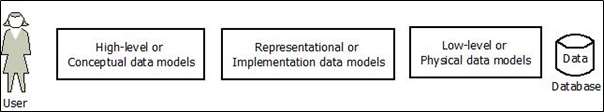
Figure: High level, Low level and Representational Data Models
High Level/Conceptual data models use concepts such as entities, attributes, and relationships. An entity represents a real-world object or concept, such as an employee or a project from the miniworld that is described in the database. An attribute represents some property of interest that further describes an entity, such as the employee’s name or salary. A relationship among two or more entities represents an association among the entities, for example, a works-on relationship between an employee and a project. This module presents the Entity-Relationship model—a popular high-level conceptual data model. We will also describe additional abstractions used for advanced modeling, such as generalization, specialization, and aggregation.
Representational or implementation data models are the models used most frequently in traditional commercial DBMSs. These include the widely used relational data model, as well as the so-called legacy data models—the network and hierarchical models—that have been widely used in the past. Module 3 is devoted to the relational data model, and its constraints. The SQL standard for relational databases is described in Module 4. Representational data models represent data by using record structures and hence are sometimes called record-based data models.
We can regard the object data model as an example of a new family of higher-level implementation data models that are closer to conceptual data models. A standard for object databases called the ODMG object model has been proposed by the Object Data Management Group (ODMG). Object data models are also frequently utilized as high-level conceptual models, particularly in the software engineering domain.
Physical data models describe how data is stored as files in the computer by representing information such as record formats, record orderings, and access paths. An access path is a structure that makes the search for particular database records efficient. An index is an example of an access path that allows direct access to data using an index term or a keyword. It is similar to the index at the end of this book, except that it may be organized in a linear, hierarchical (tree-structured), or some other fashion.
Models may be classified in the following classes according to the aim of modeling:
- Descriptive—The primary purpose of such models is to describe or understand phenomena or complex machinery. For example, meteorologists build models to understand and predict weather, investment companies build models of share markets to understand the share market and to predict share prices or share index movements; and a high school teacher may build simple models to describe or explain some scientific concept to students. The aim for such models is to describe or understand what is being modeled.
- Prescriptive—The primary purpose of prescriptive models is to clearly specify what a piece of machinery or software is supposed to do. In some cases prototype models may be built to specify how something is supposed to behave or look. The aim for such models is to specify what is being modeled. As an example, it has been shown that prescriptive models of human problem solving are able to explain how humans solve problems.
- Representative—The primary purpose of such models is to simulate the behaviour of some phenomena or machinery. For example, computer games that simulate racing cars may be considered representative models. Representative models have been built in many other fields, for example, models of face recognition techniques. The aim for such models is to simulate what is being modeled.
A model does not have to belong to one class; it can belong to more than one class. Database models are normally prescriptive since they prescribe or specify what the database system is supposed to do although they also serve a descriptive role in helping communication between the designer and the customer by describing what the database would include. Therefore before the data available in an enterprise can be put in a DBMS, a database model or an overall abstract view of the enterprise data must be developed. The view can then be translated into a form that is acceptable by the DBMS. Although at first sight a modeling task may appear trivial, it is a very complex process for large database systems since the process often involves making compromises between what the users want and what can be realistically implemented.
Classification of Database Management Systems
Several criteria are normally used to classify DBMSs. The first is the data model on which the DBMS is based.
Based on data model
- The main data model used in many current commercial DBMSs is the relational data model. The object data model has been implemented in some commercial systems but has not had widespread use. Many legacy applications still run on database systems based on the hierarchical and network data models.
- The relational DBMSs (RDBMS) are evolving continuously, and, in particular, have been incorporating many of the concepts that were developed in object databases. This has led to a new class of DBMSs called object-relational DBMSs (ORDBMS). We can categorize DBMSs based on the data model: relational, object, object-relational, hierarchical, network, and other.
- More recently, some experimental DBMSs are based on the XML (eXtended Markup Language) model, which is a tree-structured (hierarchical) data model. These have been called native XML DBMSs. Several commercial relational DBMSs have added XML interfaces and storage to their products.
Based on number of users
- The second criterion used to classify DBMSs is the number of users supported by the system. Single-user systems support only one user at a time and are mostly used with PCs.
- Multiuser systems, which include the majority of DBMSs, support concurrent multiple users.
Based on number of sites
- The third criterion is the number of sites over which the database is distributed. A DBMS is centralized if the data is stored at a single computer site. A centralized DBMS can support multiple users, but the DBMS and the database reside totally at a single computer site.
- A distributed DBMS (DBMS) can have the actual database and DBMS software distributed over many sites, connected by a computer network.
- Homogeneous DDBMSs use the same DBMS software at all the sites, whereas heterogeneous DDBMSs can use different DBMS software at each site. It is also possible to develop middleware software to access several autonomous preexisting databases stored under heterogeneous DBMSs. This leads to a federated DBMS (or multidatabase system), in which the participating DBMSs are loosely coupled and have a degree of local autonomy.
Based on cost
The fourth criterion is cost. It is difficult to propose a classification of DBMSs based on cost. Today we have open source (free) DBMS products like MySQL and PostgreSQL that are supported by third-party vendors with additional services.
Let us briefly elaborate on the main criterion for classifying DBMSs: the data model.
The relational model uses a collection of tables to represent both data and the relationships among those data. Each table has multiple columns, and each column has a unique name. Tables are also known as relations. The relational model is an example of a record-based model. Record-based models are so named because the database is structured in fixed-format records of several types. Each table contains records of a particular type. Each record type defines a fixed number of fields, or attributes. The columns of the table correspond to the attributes of the record type. The relational data model is the most widely used data model, and a vast majority of current database systems are based on the relational model. Module 3 covers the relational model in detail.
The object data model defines a database in terms of objects, their properties, and their operations. Objects with the same structure and behavior belong to a class, and classes are organized into hierarchies (or acyclic graphs). The operations of each class are specified in terms of predefined procedures called methods. Relational DBMSs have been extending their models to incorporate object database concepts and other capabilities; these systems are referred to as object-relational or extended relational systems.
The XML model has emerged as a standard for exchanging data over the Web, and has been used as a basis for implementing several prototype native XML systems. XML uses hierarchical tree structures. It combines database concepts with concepts from document representation models. Data is represented as elements; with the use of tags, data can be nested to create complex hierarchical structures. This model conceptually resembles the object model but uses different terminology. XML capabilities have been added to many commercial DBMS products.
Database Design
Database systems are designed to manage large bodies of information. These large bodies of information do not exist in isolation. They are part of the operation of some enterprise whose end product may be information from the database or may be some device or service for which the database plays only a supporting role.
Conceptual modeling is a very important phase in designing a successful database application. Generally, the term database application refers to a particular database and the associated programs that implement the database queries and updates. For example, a BANK database application that keeps track of customer accounts would include programs that implement database updates corresponding to customer deposits and withdrawals. These programs provide user-friendly graphical user interfaces (GUIs) utilizing forms and menus for the end users of the application— the bank tellers, in this example. Hence, a major part of the database application will require the design, implementation, and testing of these application programs.
Traditionally, the design and testing of application programs has been considered to be part of software engineering rather than database design. In many software design tools, the database design methodologies and software engineering methodologies are intertwined since these activities are strongly related.
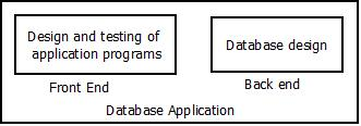
Figure: Database Application
In this module, we follow the traditional approach of concentrating on the database structures and constraints during conceptual database design. The design of application programs is typically covered in software engineering courses. We present the modeling concepts of the Entity-Relationship (ER) model, which is a popular high-level conceptual data model. This model and its variations are frequently used for the conceptual design of database applications, and many database design tools employ its concepts. We describe the basic data-structuring concepts and constraints of the ER model and discuss their use in the design of conceptual schemas for database applications. We also present the diagrammatic notation associated with the ER model, known as ER diagrams.
Phases of Database Modeling
Figure below shows a simplified overview of the database design process. The first step shown is requirements collection and analysis. During this step, the database designers interview prospective database users to understand and document their data requirements. The result of this step is a concisely written set of users’ requirements. These requirements should be specified in as detailed and complete a form as possible. In parallel with specifying the data requirements, it is useful to specify the known functional requirements of the application. These consist of the user defined operations (or transactions) that will be applied to the database, including both retrievals and updates. In software design, it is common to use data flow diagrams, sequence diagrams, scenarios, and other techniques to specify functional requirements.
Once the requirements have been collected and analyzed, the next step is to create a conceptual schema for the database, using a high-level conceptual data model. This step is called conceptual design. The conceptual schema is a concise description of the data requirements of the users and includes detailed descriptions of the entity types, relationships, and constraints; these are expressed using the concepts provided by the high-level data model. Because these concepts do not include implementation details, they are usually easier to understand and can be used to communicate with nontechnical users. The high-level conceptual schema can also be used as a reference to ensure that all users’ data requirements are met and that the requirements do not conflict. This approach enables database designers to concentrate on specifying the properties of the data, without being concerned with storage and implementation details. This makes it is easier to create a good conceptual database design.
During or after the conceptual schema design, the basic data model operations can be used to specify the high-level user queries and operations identified during functional analysis. This also serves to confirm that the conceptual schema meets all the identified functional requirements. Modifications to the conceptual schema can be introduced if some functional requirements cannot be specified using the initial schema.
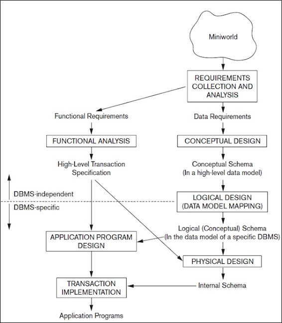
Figure: Phases of database design
The next step in database design is the actual implementation of the database, using a commercial DBMS. Most current commercial DBMSs use an implementation data model—such as the relational or the object-relational database model—so the conceptual schema is transformed from the high-level data model into the implementation data model. This step is called logical design or data model mapping; its result is a database schema in the implementation data model of the DBMS. Data model mapping is often automated or semi automated within the database design tools.
The last step is the physical design phase, during which the internal storage structures, file organizations, indexes, access paths, and physical design parameters for the database files are specified. In parallel with these activities, application programs are designed and implemented as database transactions corresponding to the high level transaction specifications.
Summary
The complexity of mapping the enterprise data to a database management system can be reduced by dividing the process into two phases. The first phase as noted above involves building an overall view (or model) of the real world which is the enterprise. This process is often called conceptual modeling. The objective of the model is to represent, as accurately as possible, the information structures of the enterprise that are of interest and independent of all physical considerations. This model is sometimes called an enterprise conceptual schema (a schema essentially shows the structure of the data in a database). The process of developing the model may be considered as the requirements analysis of the database development life cycle.This phase assists in communication between the users and designers of the database system. This model is then mapped in the second phase, and the logical design phase, to the database schema appropriate for the database model to be used. The logical design process is an abstraction process which captures the meaning of enterprise data without getting involved in the details of individual data values or details of the DBMS to be used for implementation.
As noted earlier, when the database is complex, the database design phase is challenging. A number of techniques are available for database data modeling but we discuss only one such technique popular and easy to understand. The technique uses a convenient representation that enables the database designer to view the data from the point of view of the whole enterprise. This well known technique is called Entity Relationship Model.
A Sample Database Application
In this section we describe a sample database application, called COMPANY, which serves to illustrate the basic ER model concepts and their use in schema design. We list the data requirements for the database here, and then create its conceptual schema step-by-step as we introduce the modeling concepts of the ER model. The COMPANY database keeps track of a company’s employees, departments, and projects. Suppose that after the requirements collection and analysis phase, the database designers provide the following description of the miniworld—the part of the company that will be represented in the database.
- The company is organized into departments. Each department has a unique name, a unique number, and a particular employee who manages the department. We keep track of the start date when that employee began managing the department. A department may have several locations.
- A department controls a number of projects, each of which has a unique name, a unique number, and a single location.
- We store each employee’s name, Social Security number, address, salary, gender, and birth date. An employee is assigned to one department, but may work on several projects, which are not necessarily controlled by the same department. We keep track of the current number of hours per week that an employee works on each project. We also keep track of the direct supervisor of each employee (who is another employee).
- We want to keep track of the dependents of each employee for insurance purposes. We keep each dependent’s first name, gender, and relationship to the employee.
Entity Relationship (E-R) Model
The Entity-Relationship model (E-R model) is a widely used database modeling technique because it is simple and relatively easy to understand. The method facilitates communication between the database designer and the end user. It enables an abstract global view (that is. the enterprise conceptual schema) of the enterprise application to be developed without any consideration of efficiency of the ultimate database. The Entity-Relationship model was originally proposed in 1976 by Peter Chen although many variants of the technique have subsequently been devised.
E-R modeling is based on the concept that organizations consist of people, facilities and objects. These components of an enterprise interact with each other to achieve certain goals of the enterprise. As an example, a book publishing business which involves books, authors, printers, distributors, editors, sales data and so on.
All such things that are of interest to the enterprise are called entities and their interactions are called relationships. To develop a database model based on the E-R model involves identifying the entities and relationships of interest. These are often displayed in an E-R diagram. Before discussing these, we need to describe an entity and a relationship.
The entity-relationship (E-R) data model was developed to facilitate database design by allowing specification of an enterprise schema that represents the overall logical structure of a database. The E-R model is very useful in mapping the meanings and interactions of real-world enterprises onto a conceptual schema. Because of this usefulness, many database-design tools draw on concepts from the E-R model.
The ER model describes data as entities, relationships, and attributes. which we study first.
The E-R model also has an associated diagrammatic representation, the E-R diagram, which we study later in this module.
Entities
The basic object that the ER model represents is an entity, which is a thing in the real world with an independent existence. An entity may be an object with a physical existence (for example, a particular person, car, house, or employee) or it may be an object with a conceptual existence (for instance, a company, a job, or a university course).
An entity is a real or abstract object. It may be a person, a place, a building, or an event like a contract or a concert or an order that can be distinctly identified and is of interest. An entity exists independent of what does or does not exist in an enterprise.
Although entities are often concrete like a company, an entity may be abstract like an idea, concept or an event. Whether an entity is real or abstract, the model makes no distinction between them but they must be something about which information is important.
The kind of entities needed by a database depends on the requirements of the applications. It is usually not possible to decide which entities are of interest to an enterprise based on direct observations of things in an enterprise. That is why a model must be developed to identify all entities that are of interest to an enterprise.
An entity must of course be identifiable so it must have a name or an identifier. In addition an entity must have some information beyond its identifier for it to be an entity. A model is only going to reflect the perspective of a certain application. Often it will not reflect the whole enterprise. The part of an enterprise that is of interest is called the Universe of Discourse.
Attributes
Each entity has attributes—the particular properties that describe it. For example, an EMPLOYEE entity may be described by the employee’s name, age, address, salary, and job. A particular entity will have a value for each of its attributes. The attribute values that describe each entity become a major part of the data stored in the database.
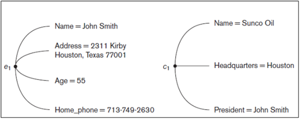
Figure: Two entities, EMPLOYEE e1, and COMPANY c1, and their attributes.
Figure shows two entities and the values of their attributes. The EMPLOYEE entity e1 has four attributes: Name, Address, Age, and Home_phone; their values are ‘John Smith,’ ‘2311 Kirby, Houston, Texas 77001’, ‘55’, and ‘713-749-2630’, respectively. The COMPANY entity c1 has three attributes: Name, Headquarters, and President; their values are ‘Sunco Oil’, ‘Houston’, and ‘John Smith’, respectively.
Types of attributes
Several types of attributes occur in the ER model: simple versus composite, single valued
versus multivalued, and stored versus derived. First we define these attribute types and illustrate their use via examples. Then we discuss the concept of a NULL value for an attribute.
Composite versus Simple (Atomic) Attributes.
Composite attributes can be divided into smaller subparts, which represent more basic attributes with independent meanings. For example, the Address attribute of the EMPLOYEE entity shown in Figure 5 can be subdivided into Street_address, City, State, and Zip, with the values ‘2311 Kirby’, ‘Houston’, ‘Texas’, and ‘77001.’
Attributes that are not divisible are called simple or atomic attributes.
Composite attributes can form a hierarchy; for example, Street_address can be further subdivided into three simple component attributes: Number, Street, and Apartment_number, as shown in Figure 6. The value of a composite attribute is the concatenation of the values of its component simple attributes.
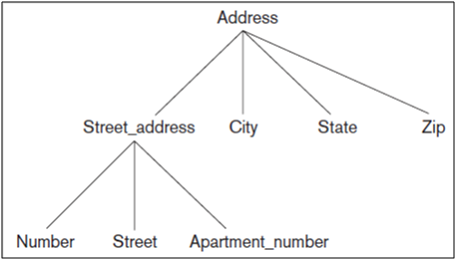
Figure: A hierarchy of composite attributes.
Composite attributes are useful to model situations in which a user sometimes refers to the composite attribute as a unit but at other times refers specifically to its components. If the composite attribute is referenced only as a whole, there is no need to subdivide it into component attributes. For example, if there is no need to refer to the individual components of an address (Zip Code, street, and so on), then the whole address can be designated as a simple attribute.
Single-Valued versus Multivalued Attributes
Most attributes have a single value for a particular entity; such attributes are called single-valued. For example, Age is a single-valued attribute of a person.
In some cases an attribute can have a set of values for the same entity—for instance, a Colors attribute for a car, or a College_degrees attribute for a person. Cars with one color have a single value, whereas two-tone cars have two color values. Similarly, one person may not have a college degree, another person may have one, and a third person may have two or more degrees; therefore, different people can have different numbers of values for the College_degrees attribute. Such attributes are called multivalued. A multivalued attribute may have lower and upper bounds to constrain the number of values allowed for each individual entity. For example, the Colors attribute of a car may be restricted to have between one and three values, if we assume that a car can have three colors at most.
Stored versus Derived Attributes
In some cases, two (or more) attribute values are related—for example, the Age and Birth_date attributes of a person. For a particular person entity, the value of Age can be determined from the current (today’s) date and the value of that person’s Birth_date. The Age attribute is hence called a derived attribute and is said to be derivable from the Birth_date attribute, which is called a stored attribute. Some attribute values can be derived from related entities; for example, an attribute Number_of_employees of a DEPARTMENT entity can be derived by counting the number of employees related to (working for) that department.
NULL Values
In some cases, a particular entity may not have an applicable value for an attribute. For example, the Apartment_number attribute of an address applies only to addresses that are in apartment buildings and not to other types of residences, such as single-family homes. Similarly, a College_degrees attribute applies only to people with college degrees. For such situations, a special value called NULL is created. An address of a single-family home would have NULL for its Apartment_number attribute, and a person with no college degree would have NULL for College_degrees. NULL can also be used if we do not know the value of an attribute for a particular entity—for example, if we do not know the home phone number of ‘John Smith’ in Figure 5. The meaning of the former type of NULL is not applicable, whereas the meaning of the latter is unknown. The unknown category of NULL can be further classified into two cases.
- The first case arises when it is known that the attribute value exists but is missing—for instance, if the Height attribute of a person is listed as NULL.
- The second case arises when it is not known whether the attribute value exists—for example, if the Home_phone attribute of a person is NULL.
Complex Attributes
Notice that, in general, composite and multivalued attributes can be nested arbitrarily. We can represent arbitrary nesting by grouping components of a composite attribute between parentheses () and separating the components with commas, and by displaying multivalued attributes between braces { }. Such attributes are called complex attributes. For example, if a person can have more than one residence and each residence can have a single address and multiple phones, an attribute Address_phone for a person can be specified as shown in Figure. Both Phone and Address are themselves composite attributes.

Figure: A complex attribute: Address_phone.
Entity Types, Entity Sets
A database usually contains groups of entities that are similar. For example, a company employing hundreds of employees may want to store similar information concerning each of the employees. These employee entities share the same attributes, but each entity has its own value(s) for each attribute.
An entity type defines a collection (or set) of entities that have the same attributes. Each entity type in the database is described by its name and attributes. Figure below shows two entity types: EMPLOYEE and COMPANY, and a list of some of the attributes for each. A few individual entities of each type are also illustrated, along with the values of their attributes.
The collection of all entities of a particular entity type in the database at any point in time is called an entity set; the entity set is usually referred to using the same name as the entity type. For example, EMPLOYEE refers to both a type of entity as well as the current set of all employee entities in the database.
An entity type describes the schema or intension for a set of entities that share the same structure. The collection of entities of a particular entity type is grouped into an entity set, which is also called the extension of the entity type.
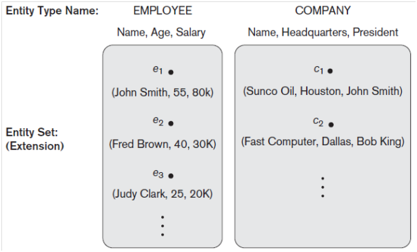
Figure: Two entity types, EMPLOYEE and COMPANY, and some member entities of each.
Entities are classified into different entity sets (or entity types). An entity set is a set of objects called entity instances or entity occurrences. An entity instance is an individual object of a given entity type. For example, all employees may constitute an entity set Employee with a particular employee (say, John Smith) being an instance of Employee.
An entity may belong to one or more entity sets. For example, an employee would belong to Employee and can also belong to another entity set Works_on. Entity sets therefore are not always disjointed.
Repeating what has been noted above, an entity set or entity type is a collection of (usually more than one) entity instances of the same type. A clear distinction therefore needs to be made between the terms entity set or entity type and entity instance.
Key Attributes of an Entity Type
An important constraint on the entities of an entity type is the key or uniqueness constraint on attributes. An entity type usually has one or more attributes whose values are distinct for each individual entity in the entity set. Such an attribute is called a key attribute, and its values can be used to identify each entity uniquely.
For example, the Name attribute is a key of the COMPANY entity type in Figure 8 because no two companies are allowed to have the same name. For the PERSON entity type, a typical key attribute is Ssn (Social Security number). Sometimes several attributes together form a key, meaning that the combination of the attribute values must be distinct for each entity. If a set of attributes possesses this property, the proper way to represent this in the ER model that we describe here is to define a composite attribute and designate it as a key attribute of the entity type. Notice that such a composite key must be minimal; that is, all component attributes must be included in the composite attribute to have the uniqueness property. Superfluous attributes must not be included in a key. In ER diagrammatic notation, each key attribute has its name underlined.
Specifying that an attribute is a key of an entity type means that the preceding uniqueness property must hold for every entity set of the entity type. Hence, it is a constraint that prohibits any two entities from having the same value for the key attribute at the same time. It is not the property of a particular entity set; rather, it is a constraint on any entity set of the entity type at any point in time. This key constraint (and other constraints we discuss later) is derived from the constraints of the miniworld that the database represents.
Some entity types have more than one key attribute. For example, each of the Vehicle_id and Registration attributes of the entity type CAR is a key in its own right. An entity type may also have no key, in which case it is called a weak entity type.
In our diagrammatic notation, if two attributes are underlined separately, then each is a key on its own. Unlike the relational model, there is no concept of primary key in the ER model that we present here; the primary key will be chosen during mapping to a relational schema.
Value Sets (Domains) of Attributes
Each simple attribute of an entity type is associated with a value set (or domain of values), which specifies the set of values that may be assigned to that attribute for each individual entity. In Figure above, if the range of ages allowed for employees is between 16 and 70, we can specify the value set of the Age attribute of EMPLOYEE to be the set of integer numbers between 16 and 70. Similarly, we can specify the value set for the Name attribute to be the set of strings of alphabetic characters separated by blank characters, and so on. Value sets are not displayed in ER diagrams, and are typically specified using the basic data types available in most programming languages, such as integer, string, Boolean, float, enumerated type, subrange, and so on. Additional data types to represent common database types such as date, time, and other concepts are also employed.
The value set provides all possible values. Usually only a small number of these values exist in the database at a particular time. Those values represent the data from the current state of the miniworld. They correspond to the data as it actually exists in the miniworld.
Initial Conceptual Design of the COMPANY Database
We can now define the entity types for the COMPANY database, based on the requirements described in Section 6. After defining several entity types and their attributes here, we refine our design in next section after we introduce the concept of a relationship. According to the requirements listed in previous section, we can identify four entity types—one corresponding to each of the four items in the specification:
- An entity type DEPARTMENT with attributes Name, Number, Locations, Manager, and Manager_start_date. Locations is the only multivalued attribute. We can specify that both Name and Number are (separate) key attributes because each was specified to be unique.
- An entity type PROJECT with attributes Name, Number, Location, and Controlling_department. Both Name and Number are (separate) key attributes.
- An entity type EMPLOYEE with attributes Name, Ssn, Sex, Address, Salary, Birth_date, Department, and Supervisor. Both Name and Address may be composite attributes; however, this was not specified in the requirements. We must go back to the users to see if any of them will refer to the individual components of Name—First_name, Middle_initial, Last_name—or of Address.
- An entity type DEPENDENT with attributes Employee, Dependent_name, Sex, Birth_date, and Relationship (to the employee).
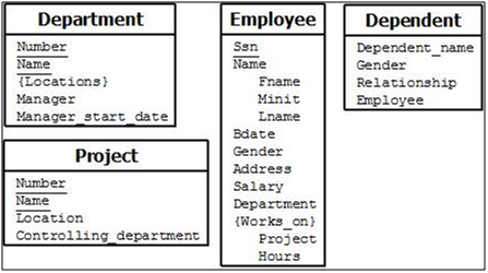
Figure: Preliminary design
So far, we have not represented the fact that an employee can work on several projects, nor have we represented the number of hours per week an employee works on each project. This characteristic is listed as part of the third requirement in next Section, and it can be represented by a multivalued composite attribute of EMPLOYEE called Works_on with the simple components (Project, Hours). Alternatively, it can be represented as a multivalued composite attribute of PROJECT called Workers with the simple components (Employee, Hours). We choose the first alternative in Figure 9, which shows each of the entity types just described. The Name attribute of EMPLOYEE is shown as a composite attribute, presumably after consultation with the users.
Relationship Types, Relationship Sets
In Preliminary design Figure there are several implicit relationships among the various entity types. In fact, whenever an attribute of one entity type refers to another entity type, some relationship exists.
For example, the attribute Manager of DEPARTMENT refers to an employee who manages the department; the attribute Controlling_department of PROJECT refers to the department that controls the project; the attribute Supervisor of EMPLOYEE refers to another employee (the one who supervises this employee); the attribute Department of EMPLOYEE refers to the department for which the employee works; and so on.
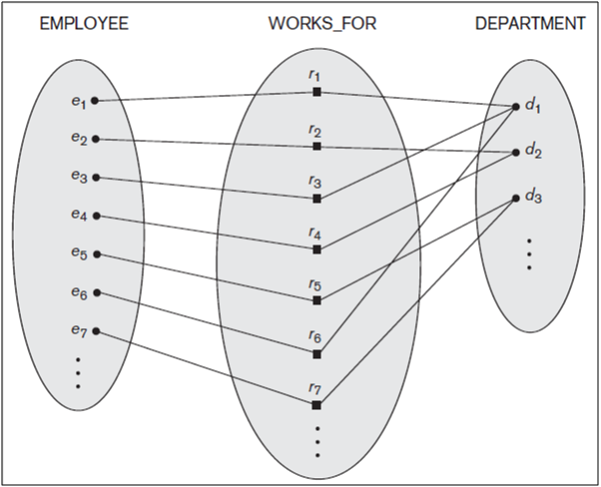
Figure: Relationship type WORKS_FOR between EMPLOYEE and DEPARTMENT.
In the ER model, these references should not be represented as attributes but as relationships, which are discussed in this section. The COMPANY database schema will be refined to represent relationships explicitly. In the initial design of entity types, relationships are typically captured in the form of attributes. As the design is refined, these attributes get converted into relationships between entity types.
A relationship type R among n entity types E1, E2, ..., En defines a set of associations—
or a relationship set—among entities from these entity types.
As for the case of entity types and entity sets, a relationship type and its corresponding relationship set are customarily referred to by the same name, R.
Participation
Each of the entity types E1, E 2, ..., En is said to participate in the relationship type R.
Relationship Instance
A relationship instance in an E-R schema represents an association between the named entities in the real-world enterprise that is being modeled.
Informally, each relationship instance ri in R is an association of entities, where the association includes exactly one entity from each participating entity type. Each such relationship instance ri represents the fact that the entities participating in ri are related in some way in the corresponding miniworld situation.
For example, consider a relationship type WORKS_FOR between the two entity types EMPLOYEE and DEPARTMENT, which associates each employee with the department for which the employee works in the corresponding entity set. Each relationship instance in the relationship set WORKS_FOR associates one EMPLOYEE entity and one DEPARTMENT entity. Figure 7.9 illustrates this example, where each relationship instance ri is shown connected to the EMPLOYEE and DEPARTMENT entities that participate in ri. In the miniworld represented by Figure 10, employees e1, e3, and e6 work for department d1; employees e2 and e4 work for department d2; and employees e5 and e7 work for department d3.
In ER diagrams, relationship types are displayed as diamond-shaped boxes, which are connected by straight lines to the rectangular boxes representing the participating entity types. The relationship name is displayed in the diamond-shaped box.
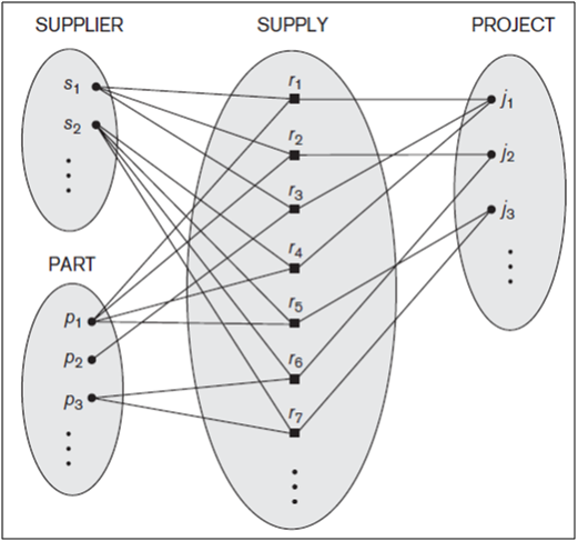
Figure: Some relationship instances in the SUPPLY ternary relationship set.
Relationship Degree
Degree of a Relationship Type. The degree of a relationship type is the number of participating entity types. Hence, the WORKS_FOR relationship is of degree two. A relationship type of degree two is called binary, and one of degree three is called ternary. An example of a ternary relationship is SUPPLY, shown in Figure 11, where each relationship instance ri associates three entities—a supplier s, a part p, and a project j—whenever s supplies part p to project j. Relationships can generally be of any degree, but the ones most common are binary relationships. Higher degree relationships are generally more complex than binary relationships.
Relationships as Attributes
It is sometimes convenient to think of a binary relationship type in terms of attributes. Consider the WORKS_FOR relationship type. One can think of an attribute called Department of the EMPLOYEE entity type, where the value of Department for each EMPLOYEE entity is (a reference to) the DEPARTMENT entity for which that employee works. Hence, the value set for this Department attribute is the set of all DEPARTMENT entities, which is the DEPARTMENT entity set. This is what we did in Figure 9 when we specified the initial design of the entity type EMPLOYEE for the COMPANY database. However, when we think of a binary relationship as an attribute, we always have two options. In this example, the alternative is to think of a multivalued attribute Employee of the entity type DEPARTMENT whose values for each DEPARTMENT entity is the set of EMPLOYEE entities who work for that department. The value set of this Employee attribute is the power set of the EMPLOYEE entity set. Either of these two attributes—Department of EMPLOYEE or Employee of DEPARTMENT—can represent the WORKS_FOR relationship type. If both are represented, they are constrained to be inverses of each other.
Role Names and Recursive Relationships
Each entity type that participates in a relationship type plays a particular role in the relationship. The role name signifies the role that a participating entity from the entity type plays in each relationship instance, and helps to explain what the relationship means. For example, in the WORKS_FOR relationship type, EMPLOYEE plays the role of employee or worker and DEPARTMENT plays the role of department or employer.
Role names are not technically necessary in relationship types where all the participating entity types are distinct, since each participating entity type name can be used as the role name. However, in some cases the same entity type participates more than once in a relationship type in different roles. In such cases the role name becomes essential for distinguishing the meaning of the role that each participating entity plays. Such relationship types are called recursive relationships.
Figure below shows an example. The SUPERVISION relationship type relates an employee to a supervisor, where both employee and supervisor entities are members of the same EMPLOYEE entity set. Hence, the EMPLOYEE entity type participates twice in SUPERVISION: once in the role of supervisor (or boss), and once in the role of supervisee (or subordinate). Each relationship instance ri in SUPERVISION associates two employee entities ej and ek, one of which plays the role of supervisor and the other the role of supervisee. In Figure 12, the lines marked ‘1’ represent the supervisor role, and those marked ‘2’ represent the supervisee role; hence, e1 supervises e2 and e3, e4 supervises e6 and e7, and e5 supervises e1 and e4. In this example, each relationship instance must be connected with two lines, one marked with ‘1’ (supervisor) and the other with ‘2’ (supervisee).
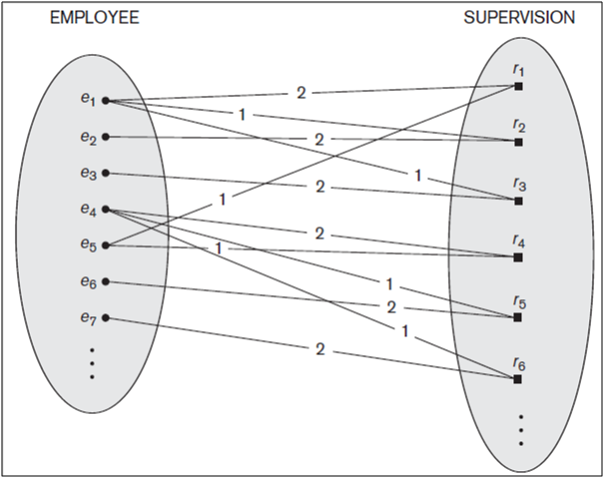
Figure: A recursive relationship SUPERVISION between EMPLOYEE in the supervisor role (1) and EMPLOYEE in the subordinate role (2).
Constraints on Binary Relationship Types
Relationship types usually have certain constraints that limit the possible combinations of entities that may participate in the corresponding relationship set. These constraints are determined from the miniworld situation that the relationships represent.
For example if the company has a rule that each employee must work for exactly one department, then we would like to describe this constraint in the schema. We can distinguish two main types of binary relationship constraints:
- cardinality ratio and
- participation.
Cardinality Ratios (Mapping Cardinalities) for Binary Relationships
The cardinality ratio for a binary relationship specifies the maximum number of relationship instances that an entity can participate in.
For example, in the WORKS_FOR binary relationship type, DEPARTMENT:EMPLOYEE is of cardinality ratio 1:N, meaning that each department can be related to (that is, employs) any number of employees, but an employee can be related to (work for) only one department. This means that for this particular relationship WORKS_FOR, a particular department entity can be related to any number of employees (N indicates there is no maximum number). On the other hand, an employee can be related to a maximum of one department.
The possible cardinality ratios for binary relationship types are 1:1, 1:N, N:1, and M:N.
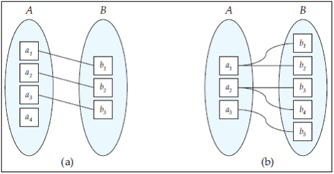
Figure : Mapping cardinalities. (a) One-to-one. (b) One-to-many.
- One-to-one. An entity in A is associated with at most one entity in B, and an entity in B is associated with at most one entity in A. (Figure a)
- One-to-many. An entity in A is associated with any number (zero or more) of entities in B. An entity in B, however, can be associated with at most one entity in A. (Figure b)
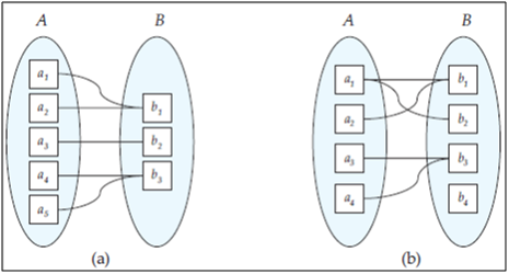
Figure: Mapping cardinalities. (a) Many-to-one. (b) Many-to-many.
- Many-to-one. An entity in A is associated with at most one entity in B. An entity in B, however, can be associated with any number (zero or more) of entities in A. (Figure a)
- Many-to-many. An entity in A is associated with any number (zero or more) of entities in B, and an entity in B is associated with any number (zero or more) of entities in A. (Figure b)
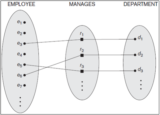
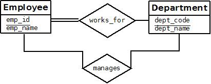
Figure: A 1:1 relationship, MANAGES.
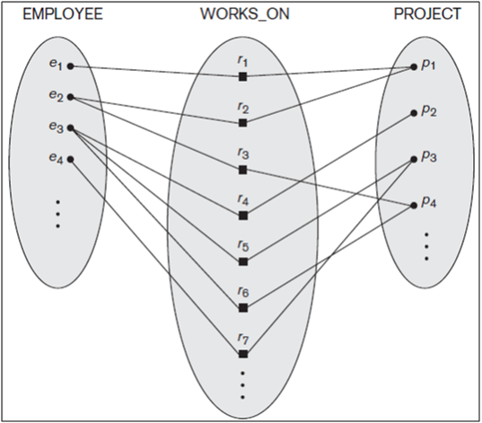
Figure: An M:N relationship, WORKS_ON.
An example of a 1:1 binary relationship is MANAGES, which relates a department entity to the employee who manages that department. This represents the miniworld constraints that—at any point in time—an employee can manage one department only and a department can have one manager only. The relationship type WORKS_ON is of cardinality ratio M:N, because the miniworld rule is that an employee can work on several projects and a project can have several employees.
Cardinality ratios for binary relationships are represented on ER diagrams by displaying 1, M, and N on the diamonds. Notice that in this notation, we can either specify no maximum (N) or a maximum of one (1) on participation. An alternative notation allows the designer to specify a specific maximum number on participation, such as 4 or 5.
Participation Constraints and Existence Dependencies
The participation of an entity set E in a relationship set R is said to be total if every entity in E participates in at least one relationship in R. If only some entities in E participate in relationships in R, the participation of entity set E in relationship R is said to be partial.
The participation constraint specifies whether the existence of an entity depends on its being related to another entity via the relationship type. This constraint specifies the minimum number of relationship instances that each entity can participate in, and is sometimes called the minimum cardinality constraint.

Figure: total and partial participation
There are two types of participation constraints—total and partial—that we illustrate by example. If a company policy states that every employee must work for a department, then an employee entity can exist only if it participates in at least one WORKS_FOR relationship instance. Thus, the participation of EMPLOYEE in WORKS_FOR is called total participation, meaning that every entity in the total set of employee entities must be related to a department entity via WORKS_FOR. Total participation is also called existence dependency. We do not expect every employee to manage a department, so the participation of EMPLOYEE in the MANAGES relationship type is partial, meaning that some or part of the set of employee entities are related to some department entity via MANAGES, but not necessarily all. We will refer to the cardinality ratio and participation constraints, taken together, as the structural constraints of a relationship type.
In ER diagrams, total participation (or existence dependency) is displayed as a double line connecting the participating entity type to the relationship, whereas partial participation is represented by a single line. Notice that in this notation, we can either specify no minimum (partial participation) or a minimum of one (total participation). The alternative notation allows the designer to specify a specific minimum number on participation in the relationship, such as 4 or 5.
Attributes of Relationship Types
Relationship types can also have attributes, similar to those of entity types. For example, to record the number of hours per week that an employee works on a particular project, we can include an attribute Hours for the WORKS_ON relationship type. Another example is to include the date on which a manager started managing a department via an attribute Start_date for the MANAGES relationship type.
Notice that attributes of 1:1 or 1:N relationship types can be migrated to one of the participating entity types. For example, the Start_date attribute for the MANAGES relationship can be an attribute of either EMPLOYEE or DEPARTMENT, although conceptually it belongs to MANAGES. This is because MANAGES is a 1:1 relationship, so every department or employee entity participates in at most one relationship instance. Hence, the value of the Start_date attribute can be determined separately, either by the participating department entity or by the participating employee (manager) entity.
For a 1:N relationship type, a relationship attribute can be migrated only to the entity type on the N-side of the relationship. For example, if the WORKS_FOR relationship also has an attribute Start_date that indicates when an employee started working for a department, this attribute can be included as an attribute of EMPLOYEE. This is because each employee works for only one department, and hence participates in at most one relationship instance in WORKS_FOR. In both 1:1 and 1:N relationship types, the decision where to place a relationship attribute—as a relationship type attribute or as an attribute of a participating entity type—is determined subjectively by the schema designer.
For M:N relationship types, some attributes may be determined by the combination of participating entities in a relationship instance, not by any single entity. Such attributes must be specified as relationship attributes. An example is the Hours attribute of the M:N relationship WORKS_ON; the number of hours per week an employee currently works on a project is determined by an employee project combination and not separately by either entity.
Weak Entity Types
Entity types that do not have key attributes of their own are called weak entity types. In contrast, regular entity types that do have a key attribute—which include all the examples discussed so far—are called strong entity types.
Entities belonging to a weak entity type are identified by being related to specific entities from another entity type in combination with one of their attribute values. We call this other entity type the identifying or owner entity type, and we call the relationship type that relates a weak entity type to its owner the identifying relationship of the weak entity type.
A weak entity type always has a total participation constraint (existence dependency) with respect to its identifying relationship because a weak entity cannot be identified without an owner entity. However, not every existence dependency results in a weak entity type. For example, a DRIVER_LICENSE entity cannot exist unless it is related to a PERSON entity, even though it has its own key (License_number) and hence is not a weak entity.
Consider the entity type DEPENDENT, related to EMPLOYEE, which is used to keep track of the dependents of each employee via a 1:N relationship. In our example, the attributes of DEPENDENT are Name (the first name of the dependent), Gender, and Relationship (to the employee). Two dependents of two distinct employees may, by chance, have the same values for Name, Gender, and Relationship, but they are still distinct entities. They are identified as distinct entities only after determining the particular employee entity to which each dependent is related. Each employee entity is said to own the dependent entities that are related to it.
A weak entity type normally has a partial key, which is the attribute that can uniquely identify weak entities that are related to the same owner entity. In our example, if we assume that no two dependents of the same employee ever have the same first name, the attribute Name of DEPENDENT is the partial key. In the worst case, a composite attribute of all the weak entity’s attributes will be the partial key.
In ER diagrams, identifying relationship is distinguished by surrounding diamonds with double lines. The partial key attribute is underlined with a dashed or dotted line.
Weak entity types can sometimes be represented as complex (composite, multivalued) attributes. In the preceding example, we could specify a multivalued attribute Dependents for EMPLOYEE, which is a composite attribute with component attributes Name, Gender, and Relationship. The choice of which representation to use is made by the database designer. One criterion that may be used is to choose the weak entity type representation if there are many attributes. If the weak entity participates independently in relationship types other than its identifying relationship type, then it should not be modeled as a complex attribute.
In general, any number of levels of weak entity types can be defined; an owner entity type may itself be a weak entity type. In addition, a weak entity type may have more than one identifying entity type and an identifying relationship type of degree higher than two.
Refining the ER Design for the COMPANY Database
We can now refine the database design in Figure 9 by changing the attributes that represent relationships into relationship types. The cardinality ratio and participation constraint of each relationship type are determined from the requirements listed in Section 6. If some cardinality ratio or dependency cannot be determined from the requirements, the users must be questioned further to determine these structural constraints.
In our example, we specify the following relationship types:
MANAGES, a 1:1 relationship type between EMPLOYEE and DEPARTMENT. EMPLOYEE participation is partial. DEPARTMENT participation is not clear from the requirements. We question the users, who say that a department must have a manager at all times, which implies total participation. The attribute Start_date is assigned to this relationship type.
WORKS_FOR, a 1:N relationship type between DEPARTMENT and EMPLOYEE. Both participations are total.
CONTROLS, a 1:N relationship type between DEPARTMENT and PROJECT. The participation of PROJECT is total, whereas that of DEPARTMENT is determined to be partial, after consultation with the users indicates that some departments may control no projects.
SUPERVISION, a 1:N relationship type between EMPLOYEE (in the supervisor role) and EMPLOYEE (in the supervisee role). Both participations are determined to be partial, after the users indicate that not every employee is a supervisor and not every employee has a supervisor.
WORKS_ON, determined to be an M:N relationship type with attribute Hours, after the users indicate that a project can have several employees working on it. Both participations are determined to be total.
DEPENDENTS_OF, a 1:N relationship type between EMPLOYEE and DEPENDENT, which is also the identifying relationship for the weak entity type DEPENDENT. The participation of EMPLOYEE is partial, whereas that of DEPENDENT is total.
After specifying the above six relationship types, we remove from the entity types in Figure 9 all attributes that have been refined into relationships. These include Manager and Manager_start_date from DEPARTMENT; Controlling_department from PROJECT; Department, Supervisor, and Works_on from EMPLOYEE; and Employee from DEPENDENT. It is important to have the least possible redundancy when we design the conceptual schema of a database.
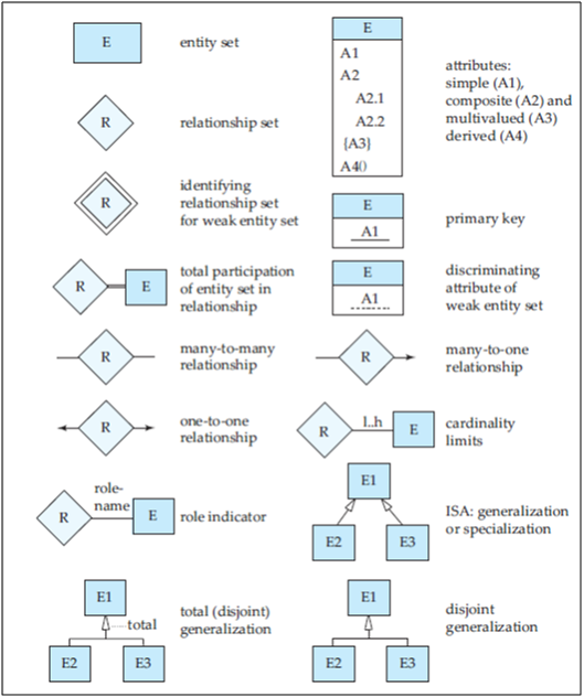
Figure: Symbols used in the E-R notation.
ER Diagrams, Naming Conventions
An E-R diagram can express the overall logical structure of a database graphically. E-R diagrams are simple and clear—qualities that may well account in large part for the widespread use of the E-R model.
Basic Structure
An E-R diagram consists of the following major components:
- Rectangles divided into two parts represent entity sets. The first part contains the name of the entity set. The second part contains the names of all the attributes of the entity set.
- Diamonds represent relationship sets.
- Undivided rectangles represent the attributes of a relationship set. Attributes that are part of the primary key are underlined.
- Lines link entity sets to relationship sets.
- Dashed lines link attributes of a relationship set to the relationship set.
- Double lines indicate total participation of an entity in a relationship set.
- Double diamonds represent identifying relationship sets linked to weak entity sets.
Proper Naming of Schema Constructs
When designing a database schema, the choice of names for entity types, attributes, relationship types, and (particularly) roles is not always straightforward. One should choose names that convey, as much as possible, the meanings attached to the different constructs in the schema.
We choose to use singular names for entity types, rather than plural ones, because the entity type name applies to each individual entity belonging to that entity type. In our ER diagrams, we will use the convention that entity type, attribute names and relationship type names have their initial letter capitalized and role names are lowercase letters.
As a general practice, given a narrative description of the database requirements, the nouns appearing in the narrative tend to give rise to entity type names, and the verbs tend to indicate names of relationship types. Attribute names generally arise from additional nouns that describe the nouns corresponding to entity types.
Another naming consideration involves choosing binary relationship names to make the ER diagram of the schema readable from left to right and from top to bottom.
Design Choices for ER Conceptual Design
It is occasionally difficult to decide whether a particular concept in the miniworld should be modeled as an entity type, an attribute, or a relationship type. In this section, we give some brief guidelines as to which construct should be chosen in particular situations.
In general, the schema design process should be considered an iterative refinement process, where an initial design is created and then iteratively refined until the most suitable design is reached. Some of the refinements that are often used include the following:
- A concept may be first modeled as an attribute and then refined into a relationship because it is determined that the attribute is a reference to another entity type. It is often the case that a pair of such attributes that are inverses of one another are refined into a binary relationship. It is important to note that in our notation, once an attribute is replaced by a relationship, the attribute itself should be removed from the entity type to avoid duplication and redundancy.
- Similarly, an attribute that exists in several entity types may be elevated or promoted to an independent entity type. For example, suppose that several entity types in a UNIVERSITY database, such as STUDENT, INSTRUCTOR, and COURSE, each has an attribute Department in the initial design; the designer may then choose to create an entity type DEPARTMENT with a single attribute Dept_name and relate it to the three entity types (STUDENT, INSTRUCTOR, and COURSE) via appropriate relationships. Other attributes/ relationships of DEPARTMENT may be discovered later.
- An inverse refinement to the previous case may be applied—for example, if an entity type DEPARTMENT exists in the initial design with a single attribute Dept_name and is related to only one other entity type, STUDENT. In this case, DEPARTMENT may be reduced or demoted to an attribute of STUDENT.
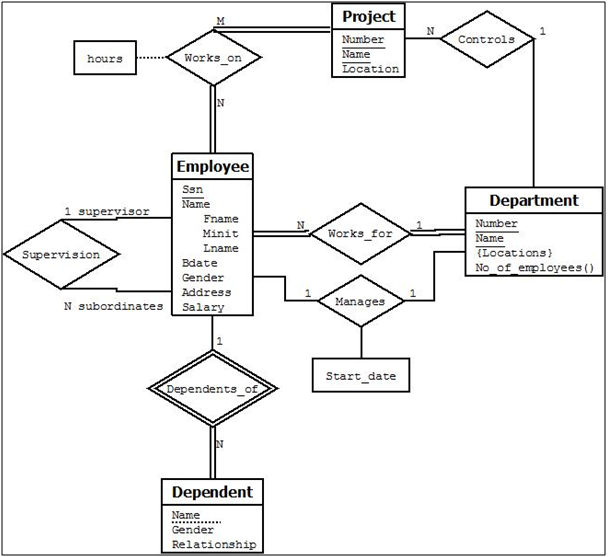
Figure: ER Diagram for Company Database
Alternative E-R Notations
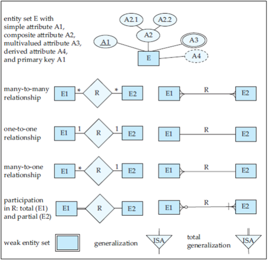
Figure 19: Alternative E-R Notations
Extended Entity-Relationship (EER) Model
The ER modeling concepts discussed so far are sufficient for representing many database schemas for traditional database applications, which include many data-processing applications in business and industry. Since the late 1970s, however, designers of database applications have tried to design more accurate database schemas that reflect the data properties and constraints more precisely. This was particularly important for newer applications of database technology, such as databases for engineering design and manufacturing (CAD/CAM), telecommunications, complex software systems, and Geographic Information Systems (GIS), among many other applications. These types of databases have more complex requirements than do the more traditional applications. This led to the development of additional semantic data modeling concepts that were incorporated into conceptual data models such as the ER model. Various semantic data models have been proposed in the literature. Many of these concepts were also developed independently in related areas of computer science, such as the knowledge representation area of artificial intelligence and the object modeling area in software engineering.
In this section, we describe features that have been proposed for semantic data models, and show how the ER model can be enhanced to include these concepts, leading to the Enhanced/Extended ER (EER) model.
In this section, we discuss the extended E-R features of specialization, generalization, higher- and lower-level entity sets, attribute inheritance, and aggregation.
Subclasses, Superclasses
The EER model includes all the modeling concepts of the ER model that were presented in earlier. In addition, it includes the concepts of subclass and superclass and the related concepts of specialization and generalization.
Another concept included in the EER model is that of a aggregation, which is used to represent a collection of entities that is the aggregation of different entity types.
Associated with these concepts is the important mechanism of attribute and relationship inheritance. Unfortunately, no standard terminology exists for these concepts, so we use the most common terminology. We also describe a diagrammatic technique for displaying these concepts when they arise in an EER schema. We call the resulting schema diagrams enhanced ER or EER diagrams.
The first Enhanced ER (EER) model concept we take up is that of a subtype or subclass of an entity type. As we discussed earlier, an entity type is used to represent both a type of entity and the entity set or collection of entities of that type that exist in the database.
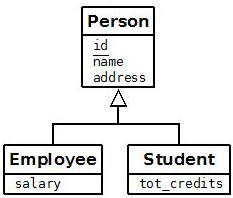
For example, the entity type EMPLOYEE describes the type (that is, the attributes and relationships) of each employee entity, and also refers to the current set of EMPLOYEE entities in the COMPANY database. In many cases an entity type has numerous subgroupings or subtypes of its entities that are meaningful and need to be represented explicitly because of their significance to the database application. For example, the entities that are members of the EMPLOYEE entity type may be distinguished further into SECRETARY, ENGINEER, MANAGER, TECHNICIAN, SALARIED_EMPLOYEE, HOURLY_EMPLOYEE, and so on. The set of entities in each of the latter groupings is a subset of the entities that belong to the EMPLOYEE entity set, meaning that every entity that is a member of one of these subgroupings is also an employee. We call each of these subgroupings a subclass or subtype or lower level of the EMPLOYEE entity type, and the EMPLOYEE entity type is called the superclass or supertype or higher level for each of these subclasses. Figure below shows how to represent these concepts diagrammatically in EER diagrams.
We call the relationship between a superclass and any one of its subclasses a superclass/subclass or supertype/subtype or simply class/subclass relationship. In our previous example, EMPLOYEE/SECRETARY and EMPLOYEE/TECHNICIAN are two class/subclass relationships. Notice that a member entity of the subclass represents the same real-world entity as some member of the superclass; for example, a SECRETARY entity ‘Joan Logano’ is also the EMPLOYEE ‘Joan Logano.’ Hence, the subclass member is the same as the entity in the superclass, but in a distinct specific role. When we implement a superclass/subclass relationship in the database system, however, we may represent a member of the subclass as a distinct database object— say, a distinct record that is related via the key attribute to its superclass entity.
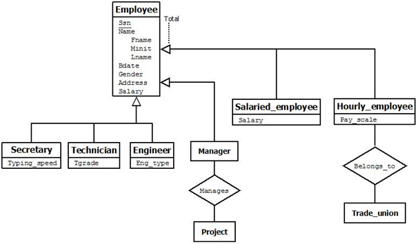
Figure: EER diagram notation to represent subclasses and specialization.
An entity cannot exist in the database merely by being a member of a subclass; it must also be a member of the superclass. Such an entity can be included optionally as a member of any number of subclasses. For example, a salaried employee who is also an engineer belongs to the two subclasses ENGINEER and SALARIED_EMPLOYEE of the EMPLOYEE entity type. However, it is not necessary that every entity in a superclass is a member of some subclass.
Specialization
Specialization is the process of defining a set of subclasses of an entity type; this entity type is called the superclass of the specialization. The set of subclasses that forms a specialization is defined on the basis of some distinguishing characteristic of the entities in the superclass.
For example, the set of subclasses {SECRETARY, ENGINEER, TECHNICIAN} is a specialization of the superclass EMPLOYEE that distinguishes among employee entities based on the job type of each employee entity. We may have several specializations of the same entity type based on different distinguishing characteristics. For example, another specialization of the EMPLOYEE entity type may yield the set of subclasses {SALARIED_EMPLOYEE, HOURLY_EMPLOYEE}; this specialization distinguishes among employees based on the method of pay.
Figure above shows how we represent a specialization diagrammatically in an EER diagram. A specialization is depicted by a hollow arrow-head pointing from the specialized (subtype) entity to the other (supertype) entity. We refer to this relationship as the ISA relationship, which stands for “is a” and represents, for example, that an ENGINEER “is a” EMPLOYEE.
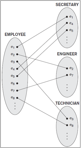
Figure: Instances of a specialization.
Figure shows a few entity instances that belong to subclasses of the {SECRETARY, ENGINEER, TECHNICIAN} specialization. Again, notice that an entity that belongs to a subclass represents the same real-world entity as the entity connected to it in the EMPLOYEE superclass, even though the same entity is shown twice; for example, e1 is shown in both EMPLOYEE and SECRETARY in Figure. As the figure suggests, a superclass/subclass relationship such as EMPLOYEE/ SECRETARY somewhat resembles a 1:1 relationship at the instance level. The main difference is that in a 1:1 relationship two distinct entities are related, whereas in a superclass/subclass relationship the entity in the subclass is the same real-world entity as the entity in the superclass but is playing a specialized role—for example, an EMPLOYEE specialized in the role of SECRETARY, or an EMPLOYEE specialized in the role of TECHNICIAN.
There are two main reasons for including class/subclass relationships and specializations in a data model. The first is that certain attributes may apply to some but not all entities of the superclass. A subclass is defined in order to group the entities to which these attributes apply. The members of the subclass may still share the majority of their attributes with the other members of the superclass. For example, in Figure 20 the SECRETARY subclass has the specific attribute Typing_speed, whereas the ENGINEER subclass has the specific attribute Eng_type, but SECRETARY and ENGINEER share their other inherited attributes from the EMPLOYEE entity type.
The second reason for using subclasses is that some relationship types may be participated in only by entities that are members of the subclass. For example, if only HOURLY_EMPLOYEES can belong to a trade union, we can represent that fact by creating the subclass HOURLY_EMPLOYEE of EMPLOYEE and relating the subclass to an entity type TRADE_UNION via the BELONGS_TO relationship type, as illustrated in EER Figure.
In summary, the specialization process allows us to do the following:
- Define a set of subclasses of an entity type
- Establish additional specific attributes with each subclass
- Establish additional specific relationship types between each subclass and other entity types or other subclasses
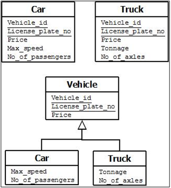
Figure: Generalizing CAR and TRUCK into the superclass VEHICLE.
Generalization
We can think of a reverse process of abstraction in which we suppress the differences among several entity types, identify their common features, and generalize them into a single superclass of which the original entity types are special subclasses.
For example, consider the entity types CAR and TRUCK shown in Figure below. Because they have several common attributes, they can be generalized into the entity type VEHICLE. Both CAR and TRUCK are now subclasses of the generalized superclass VEHICLE. We use the term generalization to refer to the process of defining a generalized entity type from the given entity types.
Notice that the generalization process can be viewed as being functionally the inverse of the specialization process. Hence, in Figure 22 we can view {CAR, TRUCK} as a specialization of VEHICLE, rather than viewing VEHICLE as a generalization of CAR and TRUCK. Similarly, in Figure 20 we can view EMPLOYEE as a generalization of SECRETARY, TECHNICIAN, and ENGINEER.
So far we have introduced the concepts of subclasses and superclass/subclass relationships, as well as the specialization and generalization processes. In general, a superclass or subclass represents a collection of entities of the same type and hence also describes an entity type; that is why superclasses and subclasses are all shown in rectangles in EER diagrams, like entity types.
Constraints on Specialization and Generalization
Our discussion refers only to specialization even though it applies to both specialization and generalization. To model an enterprise more accurately, the database designer may choose to place certain constraints on a particular generalization. One type of constraint involves determining which entities can be members of a given lower-level entity set. Such membership may be one of the following:
- Conditioned Defined
- User Defined
In general, we may have several specializations defined on the same entity type (or superclass), as shown in EER Figure. In such a case, entities may belong to subclasses in each of the specializations.
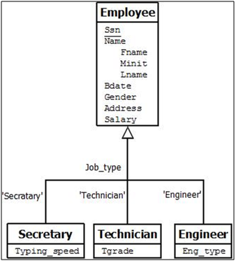
Figure: EER diagram notation for an attribute-defined specialization on Job_type.
Condition Defined
In some specializations we can determine exactly the entities that will become members of each subclass by placing a condition on the value of some attribute of the superclass. Such subclasses are called predicate-defined (or condition-defined) subclasses. For example, if the EMPLOYEE entity type has an attribute Job_type, we can specify the condition of membership in the SECRETARY subclass by the condition (Job_type = ‘Secretary’), which we call the defining predicate of the subclass. This condition is a constraint specifying that exactly those entities of the EMPLOYEE entity type whose attribute value for Job_type is ‘Secretary’ belong to the subclass.We display a predicate-defined subclass by writing the predicate condition next to the line that connects the subclass to the specialization circle.
If all subclasses in a specialization have their membership condition on the same attribute of the superclass, the specialization itself is called an attribute-defined specialization, and the attribute is called the defining attribute of the specialization. In this case, all the entities with the same value for the attribute belong to the same subclass.
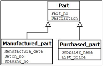
Figure: EER diagram notation for an overlapping specialization.
User Defined
When we do not have a condition for determining membership in a subclass, the subclass is called user-defined. Membership in such a subclass is determined by the database users when they apply the operation to add an entity to the subclass; hence, membership is specified individually for each entity by the user, not by any condition that may be evaluated automatically.
Two other constraints may apply to a specialization. The first is the disjointness (or disjointedness) constraint, which specifies that the subclasses of the specialization must be disjoint. For a disjoint specialization a single arrow is used.
This means that an entity can be a member of at most one of the subclasses of the specialization. A specialization that is attribute-defined implies the disjointness constraint (if the attribute used to define the membership predicate is single-valued). Figure above illustrates this case.
If the subclasses are not constrained to be disjoint, their sets of entities may be overlapping; that is, the same (real-world) entity may be a member of more than one subclass of the specialization. In ER diagram for an overlapping specialization two separate arrows are used.
The second constraint on specialization is called the completeness (or totalness) constraint, which may be total or partial. A total specialization constraint specifies that every entity in the superclass must be a member of at least one subclass in the specialization.
For example, if every EMPLOYEE must be either an HOURLY_EMPLOYEE or a SALARIED_EMPLOYEE, then the specialization {HOURLY_EMPLOYEE, SALARIED_EMPLOYEE} in Figure 20 is a total specialization of EMPLOYEE.
For example, if some EMPLOYEE entities do not belong to any of the subclasses {SECRETARY, ENGINEER, TECHNICIAN} in, then that specialization is partial.
We can specify total generalization in an E-R diagram by adding the keyword “total” in the diagram and drawing a dashed line from the keyword to the corresponding hollow arrow-head to which it applies (for a total generalization), or to the set of hollow arrow-heads to which it applies (for an overlapping generalization).
Notice that the disjointness and completeness constraints are independent. Hence, we have the following four possible constraints on specialization:
- Disjoint, total
- Disjoint, partial
- Overlapping, total
- Overlapping, partial
Of course, the correct constraint is determined from the real-world meaning that applies to each specialization. In general, a superclass that was identified through the generalization process usually is total, because the superclass is derived from the subclasses and hence contains only the entities that are in the subclasses.
Certain insertion and deletion rules apply to specialization (and generalization) as a consequence of the constraints specified earlier. Some of these rules are as follows:
- Deleting an entity from a superclass implies that it is automatically deleted from all the subclasses to which it belongs.
- Inserting an entity in a superclass implies that the entity is mandatorily inserted in all predicate-defined (or attribute-defined) subclasses for which the entity satisfies the defining predicate.
- Inserting an entity in a superclass of a total specialization implies that the entity is mandatorily inserted in at least one of the subclasses of the specialization.
Attribute Inheritance
A crucial property of the higher- and lower-level entities created by specialization and generalization is attribute inheritance. The attributes of the higher-level entity sets are said to be inherited by the lower-level entity sets. For example, SECRETARY and TECHNICIAN inherit the attributes of EMPLOYEE. Thus, SECRETARY is described by its Ssn, Name, Gender, Bdate, Address, Salary attributes, and additionally a Typing_speed attribute; TECHNICIAN is described by its Ssn, Name, Gender, Bdate, Address, Salary attributes, and additionally a Tgrade attribute. Attribute inheritance applies through all tiers of lower-level entity sets.
A lower-level entity set (or subclass) also inherits participation in the relationship sets in which its higher-level entity (or superclass) participates. Like attribute inheritance, participation inheritance applies through all tiers of lower-level entity sets.
For example, suppose the EMPLOYEE entity set participates in a relationship Works_for with DEPARTMENT. Then, the SECRETARY, TECHNICIAN, and ENGINEER entity sets, which are subclasses of the EMPLOYEE entity set, also implicitly participate in the Works_for relationship with DEPARTMENT. These entity sets can participate in any relationships in which the EMPLOYEE entity set participates.
Whether a given portion of an E-R model was arrived at by specialization or generalization, the outcome is basically the same:
- A higher-level entity set with attributes and relationships that apply to all of its lower-level entity sets.
- Lower-level entity sets with distinctive features that apply only within a particular lower-level entity set.
In what follows, although we often refer to only generalization, the properties that we discuss belong fully to both processes. EER Figure above depicts a hierarchy of entity sets. In a hierarchy, a given entity set may be involved as a lower level entity set in only one ISA relationship; that is, entity sets in this diagram have only single inheritance. If an entity set is a lower-level entity set in more than one ISA relationship, then the entity set has multiple inheritance, and the resulting structure is said to be a lattice.
Aggregation
One limitation of the E-R model is that it cannot express relationships among relationships. To illustrate the need for such a construct, consider the situation where company takes interview of job applicants. Suppose that some interviews result in job offers, whereas others do not. The schema shown in Figure is incorrect because it requires each INTERVIEW relationship instance to have a job offer in other words every interview results in Job offer which is incorrect representation.
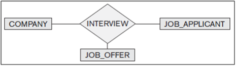
Figure: Including JOB_OFFER in a ternary relationship type (incorrect).
The schema shown below is not allowed because the ER model does not allow relationships among relationships.
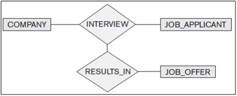
Figure: Having the RESULTS_IN relationship participate in other relationships (not allowed in ER).
The best way to model a situation such as the one just described is to use aggregation. Aggregation is an abstraction through which relationships are treated as higher-level entities. Thus, for our example, we regard the relationship set INTERVIEW (relating the entity sets COMPANY and JOB_APPLICANT) as a higher-level entity set called INTERVIEW. Such an entity set is treated in the same manner as is any other entity set. We can then create a binary relationship RESULTS_IN between INTERVIEW (entity set) and JOB_OFFER to represent which (company, job_applicant) combination results in job offer.
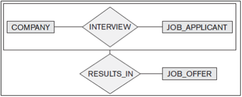
Figure: Using aggregation
Reference:
FUNDAMENTALS OF Database Systems, SIXTH EDITION
Ramez Elmasri, Shamkant B. Navathe
DATABASE SYSTEM CONCEPTS, SIXTH EDITION
Abraham Silberschatz Yale University
Henry F. Korth Lehigh University
S. Sudarshan Indian Institute of Technology, Bombay
DATABASE MANAGEMENT SYSTEM
G K Gupta
University Paper Questions and Answers
- IT - Semester III - Database Management System (CBGS)
- Computer - Semester IV - Database Management System (CBGS)
- Computer - Semester IV - Database Systems (OLD)
- Computer - Semester IV - Database Management Systems (REV)
- IT - Semester III - GUI and Database Management (REV)
- IT - Semester VI - Database System (OLD)