US4696116A - Mounting structure for rotary drum dryer - Google Patents
Mounting structure for rotary drum dryer Download PDFInfo
- Publication number
- US4696116A US4696116A US06/877,531 US87753186A US4696116A US 4696116 A US4696116 A US 4696116A US 87753186 A US87753186 A US 87753186A US 4696116 A US4696116 A US 4696116A
- Authority
- US
- United States
- Prior art keywords
- dryer
- track
- mounting structure
- tracks
- support means
- Prior art date
- Legal status (The legal status is an assumption and is not a legal conclusion. Google has not performed a legal analysis and makes no representation as to the accuracy of the status listed.)
- Expired - Fee Related
Links
- 230000033001 locomotion Effects 0.000 abstract description 3
- 230000000712 assembly Effects 0.000 description 3
- 238000000429 assembly Methods 0.000 description 3
- 239000000463 material Substances 0.000 description 3
- 235000019764 Soybean Meal Nutrition 0.000 description 1
- 229910000831 Steel Inorganic materials 0.000 description 1
- 230000010006 flight Effects 0.000 description 1
- 239000011440 grout Substances 0.000 description 1
- 238000009434 installation Methods 0.000 description 1
- 239000004455 soybean meal Substances 0.000 description 1
- 239000010959 steel Substances 0.000 description 1
- 230000003319 supportive effect Effects 0.000 description 1
Images
Classifications
-
- F—MECHANICAL ENGINEERING; LIGHTING; HEATING; WEAPONS; BLASTING
- F26—DRYING
- F26B—DRYING SOLID MATERIALS OR OBJECTS BY REMOVING LIQUID THEREFROM
- F26B11/00—Machines or apparatus for drying solid materials or objects with movement which is non-progressive
- F26B11/02—Machines or apparatus for drying solid materials or objects with movement which is non-progressive in moving drums or other mainly-closed receptacles
- F26B11/022—Arrangements of drives, bearings, supports
Definitions
- This invention relates to a mounting structure for a rotary drum dryer having annular rotation tracks which prevents spauling, flaking and pitting of the annular tracks when supported by rotating trunnion rollers. More particularly, this invention relates to a mouting structure in which each track rides on its own individual trunnion roller and which also includes thrust wheels for preventing axial movement of the dryer during rotation thereof.
- Known prior art mounting structures for rotary drum dryers typically include a continuous annular track near each end thereof supported by a pair of trunnion rollers in supportive contact with the face of the track.
- the trunnion rollers are spaced apart so that the track and dryer are cradled therein.
- Rotary drum dryers are typically very large and heavy, especially so when loaded with material to be dried such as soybean meal.
- the material enters one end of the dryer and is conveyed to the other end for exit by internal flights and sweeps which tumble and agitate the material as well as convey it gradually toward the outlet end.
- each single track supports half the total weight of the dryer. The weight supported by each track is transmitted to the two points where the track contacts the two trunnion wheels associated therewith.
- each trunnion roller exhibits a slightly different wear pattern on the face of the track. These different wear patterns often cause opposed flexing on the face of the track which results in spauling, flaking, and pitting of the track face.
- the mounting structure hereof prevents spauling, flaking, and pitting of a rotary drum dryer track.
- the mounting structure for use in rotationally supporting a horizontally disposed rotary drum dryer comprises a fixed base, a pair of proximal, continuous, annular tracks fixedly secured to the dryer, and a corresponding pair of trunnion rollers rotatably coupled with the base and adapted for contacting the face of each track respectively to thereby rotatably support the track and the dryer; the roller are located respectively on opposed sides of the dryer.
- two pairs of tracks are provided for the dryer, one pair at each end thereof, with a trunnion roller associated with each track and the axes of the trunnion rollers parallel to the axis of the dryer.
- the mounting structure advantageously includes a pair of pivotally mounted thrust wheels associated with each track for engaging the sides of the track to prevent axial shifting of the dryer--one pair of thrust wheels being in contact with one side of one track to prevent axial shifting of the dryer in one direction and another pair of thrust wheels being in contact with an opposed side of the other track to prevent axial shifting of the dryer in the other direction.
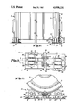
- FIG. 1 is a partial elevational view of a rotary drum dryer showing respective ends thereof supported by the mounting structure;
- FIG. 2 is a partial end view of the mounting structure
- FIG. 3 is a plan view of the mounting structure showing a pair of tracks in phantom lines.
- a mounting structure 10 for use in rotationally supporting a substantially axially horizontal, cylindrical, rotatable drum dryer 12 broadly includes base 14, a pair of continuous annular tracks 16 and 18 fixedly mounted near one end 20 of dryer 12, rotatable trunnion rollers 22 and 24, and two thrust wheel assemblies 26 and 28.
- Base 14 includes steel base plates 30 and 32, tubular beams 34, 36, 38, and 40, and conventional split pillow block ball bearings 42, 44, 46, and 48.
- Plates 30, 32 are spaced apart and preferably fixed to a concrete foundation (not shown) by appropriate conventional anchors 50 as shown.
- Grout 52 fills the gap between plates 30, 32 and the concrete foundation (FIG. 2).
- Tubular beam 34 extends across plate 30 to the inboard edge of plate 32; a pair of gussets 54 provide additional support between beam 34 and plate 30.
- Tubular beam 36, adjacent beam 34 extends across plate 32 to the inboard edge of plate 30 and is additionally supported to plate 32 by a pair of gussets 54.
- Tubular beam 38, adjacent beam 36 extends across plate 30 to the inboard edge of plate 32 and is additionally supported to plate 30 by a pair of gussets 54.
- Beams 36 and 38 narrow near the center line between plates 30, 32 as shown in FIG. 2.
- Tubular beam 40, adjacent beam 38 extends across plate 32 to the inboard edge of plate 30 and is additionally supported to plate 32 by a pair of gussets 43.
- Beam 34-40 and gussets 54 are welded to plates 30,32.
- Axially aligned bearings 42 and 44 are mounted to beams 34 and 38 respectively along the center line of plate 30.
- Axially aligned bearings 46 and 48 are mounted to beams 36 and 40 respectively along the center line of plate 32.
- Trunnion roller 22 includes rotation shaft 56 extending therethrough, the ends of which are received in bearings 42 and 44 respectively so that trunnion roller 22 is rotationally mounted between bearings 42, 44.
- trunnion roller 24 includes rotation shaft 58, the ends of which are received in bearings 46 and 48 respectively so that roller 24 is rotationally mounted thereto. Note that rollers 22 and 24 are laterally offset as shown in FIG. 3.
- Spaced-apart tracks 16 and 18 are fixedly mounted near end 20 to dryer 12 and aligned with rollers 22 and 24 respectively. With this configuration, dryer 12 is received in a "cradle" formed by rollers 22, 24 with track 16 having one point of contact with roller 22 and track 18 having one point of contact with roller 24. With this configuration, end 20 of dryer 12 is thus rotatably supported by rollers 22 and 24.
- Thrust wheels assemblies 26 and 28 each include a support beam 60, a pivot 62, a cross arm 64, two thrust wheels 66, and a support beam extension 68.
- Nut and bolt pivot 62 connects the inboard end of support beam 60 to tubular beam 38 through aligned holes (not shown) along the center line of base 14.
- Support extension 68 is welded to tubular beam 40 and slidably supports the outboard end of support beam 60.
- Cross arm extends laterally across the top of support beam 60 and is welded thereto.
- Thrust wheels 66 each include a threaded shaft 70 which is received through an appropriate hole (not shown) through cross bar 64 and secured thereto by nut 72.
- Thrust wheels 66 of thrust wheel assembly 26 engage the inboard side of track 16.
- Thrust wheels 66 of thrust wheel assembly 28 engage the outboard side of track 18 (FIG. 2).
- FIG. 1 An advantageous application of the present invention includes the use of two mounting structures 10 at each end of a dryer 12 is illustrated in FIG. 1.
- dryer 12 is rotatably supported at two points of contact at each respective end, the points of contact being where the faces of tracks 16 and 18 contact trunnion rollers 22 and 24 respectively.
- an appropriate conventional drive (not shown) rotates drum dryer 12. Trunnion rollers 22 and 24, while supporting dryer 12, also rotate. Because each roller 22, 24 supports its own respective track 16, 18, each roller-track pair forms its own wear pattern. This avoids spauling, flaking, and pitting because the wear pattern is uniform and is not counterstressed in some other direction by a second roller in contact with that track. As a result, each roller-track pair will wear in together so that total face-to-face contact is maintained. In this way, the life of the rollers and the tracks is greatly extended saving both repair and downtime expense.
- Thrust wheel assemblies 26, 28 operate to prevent dryer 12 from moving axially left or right. Thrust wheels 66 of thrust wheel assembly 28 rotate as dryer 12 rotates. Axial movement of dryer 12 to the right, as viewed in FIG. 1, is prevented by wheels 66 contacting the outboard edge of track 18. The pivotal freedom of thrust wheel assembly 28 about pivot 62 ensures that both thrust wheel 66 exert equal force on track 18. Because the wheels 66 are on opposed sides of the center plane of dryer 12, wheels 66 also aid in keeping dryer 12 laterally aligned. Thrust wheel assembly 26 performed a similar function to prevent leftward axial shifting of dryer 12 by contacting the inboard edge of track 16. With two mounting structures used on dryer 12, proper alignment of dryer 12 is doubly assured.
Landscapes
- Engineering & Computer Science (AREA)
- Mechanical Engineering (AREA)
- General Engineering & Computer Science (AREA)
- Drying Of Solid Materials (AREA)
Abstract
Description
Claims (4)
Priority Applications (1)
| Application Number | Priority Date | Filing Date | Title |
|---|---|---|---|
| US06/877,531 US4696116A (en) | 1986-06-23 | 1986-06-23 | Mounting structure for rotary drum dryer |
Applications Claiming Priority (1)
| Application Number | Priority Date | Filing Date | Title |
|---|---|---|---|
| US06/877,531 US4696116A (en) | 1986-06-23 | 1986-06-23 | Mounting structure for rotary drum dryer |
Publications (1)
| Publication Number | Publication Date |
|---|---|
| US4696116A true US4696116A (en) | 1987-09-29 |
Family
ID=25370165
Family Applications (1)
| Application Number | Title | Priority Date | Filing Date |
|---|---|---|---|
| US06/877,531 Expired - Fee Related US4696116A (en) | 1986-06-23 | 1986-06-23 | Mounting structure for rotary drum dryer |
Country Status (1)
| Country | Link |
|---|---|
| US (1) | US4696116A (en) |
Cited By (11)
| Publication number | Priority date | Publication date | Assignee | Title |
|---|---|---|---|---|
| US4765255A (en) * | 1987-12-02 | 1988-08-23 | Stella S.P.A. | Perfected system for pyrolysing and/or drying biological sludge or similar |
| US5044786A (en) * | 1989-12-07 | 1991-09-03 | Skf Gmbh | Bearing arrangement for a rotary drum |
| US5415541A (en) * | 1992-05-18 | 1995-05-16 | Krupp Polysius Ag | Rotary drum |
| US5555639A (en) * | 1995-05-18 | 1996-09-17 | Productization Inc. | Rotary drum dryer |
| US5992039A (en) * | 1998-03-12 | 1999-11-30 | Bunch; Kelly C. | Portable clothes dryer |
| USD427393S (en) * | 1998-03-12 | 2000-06-27 | Kelly C Bunch | Portable clothes dryer with external timer |
| US20020090718A1 (en) * | 2000-12-14 | 2002-07-11 | Yona Chen | Device for composting organic material and the process for composting said organic material |
| US20120312113A1 (en) * | 2010-03-01 | 2012-12-13 | Kaestingschaefer Gerhard | Drive for a rotary drum |
| GB2580507A (en) * | 2018-11-30 | 2020-07-22 | Ciilock Eng Pty Ltd | A roller assembly and a roller carriage for the same |
| US10844285B1 (en) * | 2020-05-21 | 2020-11-24 | Smart Terra Care, LLC | Remediation of organic wastes by thermal degradation of polyfluoroalkyl and microplastic contaminants |
| US20210199380A1 (en) * | 2016-02-12 | 2021-07-01 | Holcim Technology Ltd | Arrangement for supporting a rotary drum |
Citations (8)
| Publication number | Priority date | Publication date | Assignee | Title |
|---|---|---|---|---|
| US2707339A (en) * | 1952-05-15 | 1955-05-03 | Archie M Berge | Corn crib |
| US2783548A (en) * | 1955-06-08 | 1957-03-05 | Edw Renneburg & Sons Co | Rotary dryers |
| US2819130A (en) * | 1955-03-12 | 1958-01-07 | Fellner & Ziegler Gmbh | Bearings for rotary cylinders, drums and the like |
| US2908179A (en) * | 1957-08-16 | 1959-10-13 | Vulcan Iron Works | Rotary kiln |
| US3561132A (en) * | 1969-09-10 | 1971-02-09 | Phillips Petroleum Co | Carbon black drying apparatus |
| US3648992A (en) * | 1969-04-14 | 1972-03-14 | Fives Lille Cail | Support for rotary furnaces |
| US4523387A (en) * | 1983-12-08 | 1985-06-18 | Mahan Douglas P | Microwave treating mechanism |
| US4624576A (en) * | 1985-06-26 | 1986-11-25 | Bituma Construction Equipment Company | Adjustment of drum mixer trunnions |
-
1986
- 1986-06-23 US US06/877,531 patent/US4696116A/en not_active Expired - Fee Related
Patent Citations (8)
| Publication number | Priority date | Publication date | Assignee | Title |
|---|---|---|---|---|
| US2707339A (en) * | 1952-05-15 | 1955-05-03 | Archie M Berge | Corn crib |
| US2819130A (en) * | 1955-03-12 | 1958-01-07 | Fellner & Ziegler Gmbh | Bearings for rotary cylinders, drums and the like |
| US2783548A (en) * | 1955-06-08 | 1957-03-05 | Edw Renneburg & Sons Co | Rotary dryers |
| US2908179A (en) * | 1957-08-16 | 1959-10-13 | Vulcan Iron Works | Rotary kiln |
| US3648992A (en) * | 1969-04-14 | 1972-03-14 | Fives Lille Cail | Support for rotary furnaces |
| US3561132A (en) * | 1969-09-10 | 1971-02-09 | Phillips Petroleum Co | Carbon black drying apparatus |
| US4523387A (en) * | 1983-12-08 | 1985-06-18 | Mahan Douglas P | Microwave treating mechanism |
| US4624576A (en) * | 1985-06-26 | 1986-11-25 | Bituma Construction Equipment Company | Adjustment of drum mixer trunnions |
Cited By (14)
| Publication number | Priority date | Publication date | Assignee | Title |
|---|---|---|---|---|
| US4765255A (en) * | 1987-12-02 | 1988-08-23 | Stella S.P.A. | Perfected system for pyrolysing and/or drying biological sludge or similar |
| US5044786A (en) * | 1989-12-07 | 1991-09-03 | Skf Gmbh | Bearing arrangement for a rotary drum |
| US5415541A (en) * | 1992-05-18 | 1995-05-16 | Krupp Polysius Ag | Rotary drum |
| AU663451B2 (en) * | 1992-05-18 | 1995-10-05 | Krupp Polysius Ag | Rotary drum |
| US5555639A (en) * | 1995-05-18 | 1996-09-17 | Productization Inc. | Rotary drum dryer |
| USD427393S (en) * | 1998-03-12 | 2000-06-27 | Kelly C Bunch | Portable clothes dryer with external timer |
| US5992039A (en) * | 1998-03-12 | 1999-11-30 | Bunch; Kelly C. | Portable clothes dryer |
| US20020090718A1 (en) * | 2000-12-14 | 2002-07-11 | Yona Chen | Device for composting organic material and the process for composting said organic material |
| US20120312113A1 (en) * | 2010-03-01 | 2012-12-13 | Kaestingschaefer Gerhard | Drive for a rotary drum |
| US20210199380A1 (en) * | 2016-02-12 | 2021-07-01 | Holcim Technology Ltd | Arrangement for supporting a rotary drum |
| US11578920B2 (en) * | 2016-02-12 | 2023-02-14 | Holcim Technology Ltd | Arrangement for supporting a rotary drum |
| GB2580507A (en) * | 2018-11-30 | 2020-07-22 | Ciilock Eng Pty Ltd | A roller assembly and a roller carriage for the same |
| GB2580507B (en) * | 2018-11-30 | 2021-07-28 | Ciilock Eng Pty Ltd | A roller carriage assembly for a sliding panel |
| US10844285B1 (en) * | 2020-05-21 | 2020-11-24 | Smart Terra Care, LLC | Remediation of organic wastes by thermal degradation of polyfluoroalkyl and microplastic contaminants |
Similar Documents
| Publication | Publication Date | Title |
|---|---|---|
| US4696116A (en) | Mounting structure for rotary drum dryer | |
| US20060169857A1 (en) | Self-aligning trunnions for rotary dryer/mixer | |
| US6644859B2 (en) | Supporting roller set for tiltable support of a rotary drum | |
| GB1527419A (en) | Rotary drum support | |
| US3703862A (en) | Work pressure rolling assembly | |
| JP2001527478A (en) | 4-ring eccentric bearing for printing press cylinder | |
| CA2169018C (en) | Dragline with improved thrust bearing assembly supporting upper structure | |
| US5044786A (en) | Bearing arrangement for a rotary drum | |
| US5462370A (en) | Tiltable supporting roller bearing | |
| JPS6487112A (en) | Circular sawing machine | |
| US2474489A (en) | Rocker mounting for rotary bearings | |
| EP1018416A3 (en) | Roll mill for raw materials in the ceramic industry | |
| DE1064300B (en) | Storage arrangement for rotary furnaces, drying, mixing, preheating, cooling drums or the like. | |
| US2678136A (en) | Turntable for cranes and excavators | |
| SU1659764A1 (en) | Support roll of testing arrangement for wheel-mounted vehicles | |
| JPH031217B2 (en) | ||
| US4432588A (en) | Bearing to be used for a rotating body | |
| SU608043A1 (en) | Device for rotating furnace tank | |
| SU449132A1 (en) | Slewing ring | |
| JPS6363505A (en) | Cross helical roll supporter | |
| SU620557A1 (en) | Supporting-slewing arrangement | |
| JPH0129509Y2 (en) | ||
| JPS59110406A (en) | Method and device for roll shifting | |
| US4466750A (en) | Bearing segment for a sliding shoe | |
| SU400359A1 (en) | DRUM MILL |
Legal Events
| Date | Code | Title | Description |
|---|---|---|---|
| AS | Assignment |
Owner name: GUARANTY PERFORMANCE CO., INC., 1120 E. MAIN, MONT Free format text: ASSIGNMENT OF ASSIGNORS INTEREST.;ASSIGNOR:LIVINGSTON, ANDREW D.;REEL/FRAME:004569/0724 Effective date: 19860618 |
|
| AS | Assignment |
Owner name: PRODUCTIZATION, INC., 1120 EAST MAIN, INDEPENDENCE Free format text: ASSIGNMENT OF ASSIGNORS INTEREST.;ASSIGNOR:GUARANTY PERFORMANCE CO., INC.;REEL/FRAME:004763/0087 Effective date: 19870918 Owner name: PRODUCTIZATION, INC.,KANSAS Free format text: ASSIGNMENT OF ASSIGNORS INTEREST;ASSIGNOR:GUARANTY PERFORMANCE CO., INC.;REEL/FRAME:004763/0087 Effective date: 19870918 |
|
| REMI | Maintenance fee reminder mailed | ||
| LAPS | Lapse for failure to pay maintenance fees | ||
| FP | Lapsed due to failure to pay maintenance fee |
Effective date: 19910929 |
|
| STCH | Information on status: patent discontinuation |
Free format text: PATENT EXPIRED DUE TO NONPAYMENT OF MAINTENANCE FEES UNDER 37 CFR 1.362 |