EP0943723A1 - Sample taking device for a strip material or a sheet material - Google Patents
Sample taking device for a strip material or a sheet material Download PDFInfo
- Publication number
- EP0943723A1 EP0943723A1 EP99420061A EP99420061A EP0943723A1 EP 0943723 A1 EP0943723 A1 EP 0943723A1 EP 99420061 A EP99420061 A EP 99420061A EP 99420061 A EP99420061 A EP 99420061A EP 0943723 A1 EP0943723 A1 EP 0943723A1
- Authority
- EP
- European Patent Office
- Prior art keywords
- blade
- product
- strip
- sample collection
- sample
- Prior art date
- Legal status (The legal status is an assumption and is not a legal conclusion. Google has not performed a legal analysis and makes no representation as to the accuracy of the status listed.)
- Withdrawn
Links
Images


Classifications
-
- D—TEXTILES; PAPER
- D06—TREATMENT OF TEXTILES OR THE LIKE; LAUNDERING; FLEXIBLE MATERIALS NOT OTHERWISE PROVIDED FOR
- D06H—MARKING, INSPECTING, SEAMING OR SEVERING TEXTILE MATERIALS
- D06H7/00—Apparatus or processes for cutting, or otherwise severing, specially adapted for the cutting, or otherwise severing, of textile materials
- D06H7/24—Devices specially adapted for cutting-out samples
Definitions
- the present invention relates to a device for sampling of a product in a strip or in leaf.
- the purpose assigned to this device is to collect, on a product in strip or sheet, scrolling or the stop, a circular part of predefined dimension, of in the order of 10 to 20 cm in diameter, this so automatic.
- the present invention aims to remedy the inadequacy of known systems, providing a sample collection device that works from automatically with very high reliability, even in the case of very fine products without hold, and which thus allows the improvement of working conditions, while meeting the need to control the product quality during a manufacturing process and / or treatment.
- the subject of the invention is a device for taking a sample from a product in strip or sheet, scrolling or stopped, which essentially consists of a blade holder and a vacuum plate arranged along the same axis, on both sides and other of the product in strip or sheet, in scrolling or stopped, the blade holder plate being mounted rotating around the aforementioned axis and being associated with motorized rotary drive means, this plate carrying a circular blade facing the product in strip or sheet, while the vacuum plate has an annular pile intended to cooperate with the blade circular, and a central suction cup connected to a circuit of vacuum and / or pressure, at least one of two plates being movable in translation along the axis mentioned above and associated with means of displacement in translation, so as to allow the approximation and the distance between the two platforms.
- the blade holder plate still carries, advantageously, a circular plate mounted free to rotate around the aforementioned axis, inside the circular blade, and flexibly linked to the support of said blade, this platinum exerting pressure on the part of the strip or sheet product applied to the suction cup of the vacuum plate, when the two are brought together trays prior to the action of the circular blade.
- the product in tape or sheet is immobilized both inside and outside the annular area, in which the cut of the sample is carried out by means of the slide circular. This prevents wrinkles and entrainment of the produced in strip or sheet, and allows in particular reliably take samples even in the case of very fine fabrics, not holding by themselves.
- This blade can be facilitated and made more reliable by weakening the fibers or particles of the product, at the place of cutting.
- the circular blade is advantageously made as a heating blade, connected by a connector to an electrical source; the desired embrittlement is thus obtained thermally.
- the circular blade is designed as a vibrating blade, preferably a blade mounted on an ultrasonic chip, connected to a source of ultra-sounds, the embrittlement being thus obtained by ultra-sonic vibrations.
- Motorized means for rotating the blade holder plate can be constituted by a jack rotary, able to make this tray describe, and more particularly with the circular blade, a rotation at a predetermined angle, for example at a reciprocating movement, during each cycle of taking a sample.
- the blade circular cooperates with a counterpart called "heap annular ", which is a kind of sole or plate, of annular or circular shape, capable of supporting, without immediate mechanical damage, the blade pressure of possibly hot cut, animated by a movement of alternating rotation, making up for the shortcomings of blade geometry.
- the annular pile can wear out more or less quickly under the friction effect of the blade, and in case of degradation of its surface condition, it is no longer guaranteed that all the fibers of the strip or sheet product undergo the same cutting stress.
- the annular pile consists of a regenerable material, and more particularly of a metal or alloy having a very low melting point, a electric heating resistance being embedded in said annular pile. So when it becomes necessary to regenerate the active surface of the annular heap, we will send a heating current in the resistance embedded in the metal or alloy of this annular heap, to liquefy it and again get a smooth surface. The reliability of device is thus improved.
- the vacuum plate is for example mounted movable in translation on a slide, its means of movement in translation being in particular constituted by a jack.
- the blade holder plate and the depression are carried respectively by the two parallel horizontal branches of a U-shaped support which wraps around the product in strips or sheets; of preferably, the support in "U” is mounted movable in translation, in a direction transverse to that of produced in strip or sheet, to allow the taking samples at different points in the product width.
- the plate blade holder and vacuum plate are worn respectively by two movable carriages translation, synchronized, on both sides of the produced in strip or sheet, in one direction transverse, to allow sampling at different points along the width of the product.
- the device can be incorporated in a sampling machine, inserted itself in a production line and / or processing of a continuously moving strip product, the sampling machine comprising an accumulator input and output accumulator arranged respectively upstream or downstream of the sample collection. Thanks to the two accumulators, the advance of the strip product may be temporarily stopped at the sampling device of sample, to allow the intervention of this one, without interrupting the general advance of the product in strip on the manufacturing and / or processing line.
- the device is usefully supplemented by means of recovery and evacuation of the sample taken, comprising a receptacle positioned under the tray depression, and a conveyor arranged transversely to the strip product, for bringing the sample to a side of the manufacturing and / or processing line, or well in a place far from said line.
- the blade holder plate 2 includes a support 4 mounted rotating around an axis 5, perpendicular to the plane of the product in strip 1.
- the support 4 has a cavity 6 cylindrical in shape, opening facing the product in strip 1.
- the cavity 6 receives a heating blade circular 7 connected by at least one electrical connector bipolar 8 to a power source not shown, allowing the heating of the blade 7 by Joule effect, the blade temperature 7 being adjusted so suitable for product 1 to be cut.
- This heating blade 7 is integral in rotation with the support 4.
- the cavity 6 of the support 4 still receives a plate circular 9, mounted freely in rotation about the axis 5, inside the circular heating blade 7.
- the connection of the circular plate 9 with the support 4 is flexible, and allows this plate 9 to retract under the effect of an external push.
- Motorized means for rotating the blade holder plate 2 around axis 5, along arrow R, are constituted in the example represented by a jack rotary 10 mounted along axis 5.
- the vacuum plate 3 includes a support 11, mounted movable in translation along axis 5, so as to ability to describe forward / backward movement according to double arrow F.
- the support 11 has a cavity 12 of cylindrical shape, opening facing the product in strip 1.
- the cavity 12 receives an annular pile 13 for example in synthetic material, able to withstand without degradation the hot friction of the heating blade 7, and flexible enough not to destroy the cutting edge of blade 7 by friction.
- Support 11 still receives a suction cup central 14 gripping / evacuation, mounted in the cavity 12 inside the annular pile 13.
- the suction cup 14 is presented as a circular plate, comprising a network of grooves 15 which converge radially towards a central hole 16 (see in particular figure 3).
- This suction cup 14 is extended towards the rear by a chimney 17, crossed by the central hole 16 and provided to be connected to a vacuum circuit or under pressure, not shown.
- the suction cup 14 integral part of support 11, instead of being attached on this support 11.
- the sample taking device previously described, works as follows:
- the rotary actuator 10 is then actuated, which triggers the rotation of the blade holder plate 2 and, in in particular, the rotation of the heated blade 7, according to a certain angle suitable for the material to be cut.
- this angle is reached, the rotation of the blade holder plate 2 is stopped, and this plateau 2 moves back and also returns to its initial angular position.
- fibers and / or particles of the product in strip 1 were cut, along a line circular, and we thus obtained a piece cut into disc shape, the same size as the blade 7.
- the cut piece is held by vacuum on the suction cup 14 of the tray 3. To evacuate this part cut out, just remove the vacuum, and possibly to assist the evacuation of said room by sending a brief overpressure in the suction cup 14.
- Figure 4 illustrates a variant of the previously described sample taking, in which the circular blade 7, instead of being a heating blade, is mounted on an ultrasonic patch 18 placed on the support 4, between the base of this blade 7 and the bottom of the cavity 6.
- the patch 18 is connected to a source of ultrasound, not shown.
- the weakening of the product in band 1 is here caused by the ultrasonic vibration of blade 7 during the cutting phase, the functioning of the device being, for the rest, not modified from the previous description.
- the two previous embodiments are combined, that is to say that the circular blade 7 is both heated and ultrasonic vibration.
- the embrittlement of the product in strip 1, with a view to cutting it by blade 7, in this case results from the combination of a thermal action and an ultra-sonic action.
- Figure 5 shows an automatic complete sampling, generally designated by the item 19, inserted in a production line and / or treatment of the product in band 1, between a part "upstream” 20 and a "downstream” part 21 of the line.
- the machine 19 itself comprises an input accumulator 22 and an output accumulator 23, disposed respectively upstream and downstream of the sampling device sample 24, located in the central part of this machine 19 and produced according to the preceding description.
- the input accumulator 22 comprises two rollers fixed 25 and 26, and a vertically movable roller 27, on which pass the product in band 1.
- the movement of lowering of the movable roller 27 allows the upstream part 20 from the manufacturing and / or processing line to continue deliver the product in band 1, without slowing down, then that this product in band 1 is immobilized between the two plates 2 and 3 of the sample collection device 24, pressed against each other.
- the output accumulator 23 plays the role exactly the opposite of the input accumulator 22.
- This output accumulator 23 also includes rollers fixed 28, 29, 30 and 31, and a vertically movable roller 32, on which the product passes in band 1.
- the movement lowering of the movable roller 32, simultaneous with that of the movable roller 27 of the input accumulator 22, allows the product in band 1 located downstream to compensate for the stop which imposed on him in the area of the sampling device sample 24, so that the output speed of the product in band 1 remains constant, in the downstream part 21 of the line.
- the heating phase Advantageously intervenes before the immobilization of the produced in band 1, therefore in "masked time", for the sake of optimization.
- input 22 and output 23 accumulators will not described in more detail, since these are devices commonly used in manufacturing lines and / or processing of strip products with scrolling.
- the two plates 2 and 3 of the sample collection device 24 are mounted respectively on the two branches horizontal parallel of a U-shaped support 33, both plates 2 and 3 being thus maintained along the same axis 5.
- the support in "U” 33 passes on one side of the product in strip 1, while positioning the sampling device 24 at a point across the width of the product in strip 1.
- the "U" -shaped support 33 can be mounted mobile translation, perpendicular to the direction of advance of product in strip 1, by means of two slides lateral 34, so that it is possible to take samples samples across the full width of the strip product 1.
- the support in "U” is replaced by two carriages 35 and 36, sliding mounted on horizontal rails respective cross sections 37 and 38, on either side of produced in strip 1, the two carriages 35 and 36 carrying respectively the two plates 2 and 3 of the sampling 24.
- the two carriages 35 and 36 are movable, along the respective slides 37 and 38, using motorized drive devices respectively 39 and 40 which are perfectly synchronous, from so as to synchronize the movements of these two carriages 35 and 36, and thus maintain the two trays 2 and 3 along the same axis 5.
- This variant is advantageous, from the point of view of space.
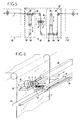
- FIGs 6 and 7 again show the means motorized translational movement of the plate to depression 3 as well as the means of recovery and sample evacuation, the details of which are visible in figure 8.
- Motorized means of translational movement of the vacuum plate 3 include a slide balls 41, and a jack 42, which allow to move and to guide in translation a movable bar 43 on which is fixed the support 11 of the vacuum plate 3.
- the means of recovery and evacuation of the sample includes a receptacle 44, in the form of hopper, positioned under the vacuum plate 3.
- These means also include a conveyor 45, arranged transversely to the product in strip 1, under the receptacle 44, the conveyor 45 being shown here as an endless belt conveyor but which can be a conveyor of any type, for example pneumatic.
- the sample falls by gravity in receptacle 44, and it reaches the upper strand of the conveyor 45, whose role is to bring this sample be on one side of the line of manufacturing and / or processing, where it can be recovered manually by an operator, either in a more far from said line.
- Figure 9 in which the numerical marks retain their previous meaning indicated in reference to figure 5, shows another gripping machine of samples 19, also inserted between a part upstream 20 and downstream part 21 of a production line and / or treatment of a product in strip 1, and comprising again an input accumulator 22 and an accumulator of outlet 23, arranged on either side of the sample collection 24.
- the sample collection device 24 is here installed on a horizontal portion of the path of the produced in strip 1, the blade holder plate 2 being located above this product in strip 1, and the tray to depression 3 being located below.
- the annular pile 13 is thus arranged horizontally, its active surface being directed upwards, which makes it possible to carry it out as a regenerable pile, made of metal or melting point alloy very low, such as indium.
- An electrical resistance not shown, embedded in this metal or alloy, allows sending an electric heating current causing its fusion and its regeneration, when it is necessary.
- roller vertically movable 32 of the output accumulator 23 must describe an upward movement, simultaneously with the downward movement of the vertically movable roller 27 of the input accumulator 22, to compensate for the stop imposed on the product in band 1 in the area of the sample collection 24.
- the sampling machine 19, previously described with reference to FIGS. 5 to 9, can be more or less automated.
- the product in strip 1 being stationary between the input accumulator 22 and the output accumulator 23, only the sample collection 24 has a functioning automatically cycled, from the actuation of a pushbutton.
- the operation of regeneration can be ordered either piecemeal by the operator, either automatically depending on preselected parameters.
- the gripping device and machine previously described samples are applicable especially to taking samples in lines of fabric manufacturing and / or processing, if applicable with sample collection at positions different from the width of the fabric concerned.
Abstract
Description
La présente invention concerne un dispositif de prélèvement d'échantillon sur un produit en bande ou en feuille. Le but assigné à ce dispositif est de prélever, sur un produit en bande ou en feuille, en défilement ou à l'arrêt, une pièce circulaire de dimension prédéfinie, de l'ordre de 10 à 20 cm de diamètre, ceci de façon automatique.The present invention relates to a device for sampling of a product in a strip or in leaf. The purpose assigned to this device is to collect, on a product in strip or sheet, scrolling or the stop, a circular part of predefined dimension, of in the order of 10 to 20 cm in diameter, this so automatic.
Dans toutes les installations de production en continu, se pose le problème du contrôle de la qualité du produit aux différents stades de son élaboration et/ou de sa transformation, pour vérifier que le déroulement du processus est conforme.In all production facilities in the problem of quality control of the product at the various stages of its development and / or its transformation, to verify that the course of the process is consistent.
Dans le cas des produits en bande ou en feuille, tels que les produits des industries textiles et papetières, le problème posé est d'une part de réussir à prélever un morceau de la bande ou feuille en défilement, sans altérer le reste du produit qui doit pouvoir continuer à défiler dans l'installation, donc sans détériorer ce produit du fait de l'opération de prélèvement, et d'autre part de ne provoquer la perturbation d'aucun des paramètres établis du processus, en évitant les à-coups, les déplacements de la bande, etc...In the case of strip or sheet products, such as textile industry products and On the one hand, the problem posed is to succeed in take a piece of the strip or sheet while scrolling, without altering the rest of the product which must be able continue to scroll through the installation, so without deteriorate this product due to the operation of levy, and secondly to only cause the disruption of any of the established process parameters, avoiding jolts, displacements of the strip, etc ...
Pour les textiles d'habillement et de décoration, et pour les textiles techniques tels que tissus de verre ou de carbone, il n'existe aucun dispositif de prise automatique d'échantillon spécifique, et donnant satisfaction.For clothing and decoration textiles, and for technical textiles such as glass fabrics or carbon, there is no catch device automatic specific sample, and giving satisfaction.
Des essais ont été faits avec des dispositifs conçus pour le papier, à base de cylindres gravés du type utilisé pour la découpe d'étiquettes. Ces essais n'ont pas donné satisfaction car, après un très court temps d'utilisation, l'usure des empreintes faisait que certaines fibres textiles n'étaient pas coupées. Les conséquences pouvaient être désastreuses car la pièce, incomplètement découpée, non seulement n'était pas prélevée, mais encore était entraínée dans la ligne de fabrication ou de traitement et pouvait occasionner des surépaisseurs très dommageables à certaines parties de machines. Il pouvait aussi se produire qu'un fil soit tiré sur toute la longueur de tissu située en aval du dispositif de prise, jusqu'à ce que l'opérateur s'en aperçoive.Tests have been done with devices designed for paper, based on engraved type cylinders used for cutting labels. These trials did not given satisfaction because after a very short time of use, the wear of the imprints made that some textile fibers were not cut. The consequences could be disastrous because the room, incompletely cut, not only was not taken, but still was dragged into the line of manufacturing or processing and could cause excess thickness very damaging to certain parts of machines. It could also happen that a thread is pulled over the entire length of fabric located downstream of the gripping device, until the operator leaves glimpse.
D'autres propositions connues consistent en un dispositif à poinçon, actionné de façon brutale et censé découper un échantillon sur un produit en cours de défilement, sans interrompre le défilement du produit à l'endroit où doit être prélevé l'échantillon - voir par exemple les brevets US 3648555 et US 4061065. De tels dispositifs, fonctionnant "à la volée", créent inévitablement des à-coups dans le matériau en cours de défilement, et ne permettent pas une découpe nette d'échantillons, notamment dans le cas d'un matériau fragile.Other known proposals consist of a punch device, brutally operated and supposed to cut a sample out of a product being scrolling, without interrupting the scrolling of the product to where the sample should be taken - see by example US patents 3648555 and US 4061065. Such devices, operating "on the fly", create inevitably jerks in the material being scroll, and do not allow a clean cut samples, especially in the case of a material brittle.
Or un dispositif automatique de prélèvement d'échantillon ne présentant pas une fiabilité absolue n'est pas utilisable dans une ligne de production en continu. Par conséquent, dans la pratique, la prise d'échantillon se fait encore manuellement, à la volée à l'aide d'un cutter. Ceci est une cause d'accidents du travail, l'opérateur étant obligé d'entrer dans la machine, à proximité de pièces et du produit en mouvement.Or an automatic sampling device of sample not having absolute reliability cannot be used in a production line in continued. Therefore, in practice, taking sample is still done manually, on the fly at using a craft knife. This is a cause of accidents work, the operator being forced to enter the machine, near moving parts and product.
D'autres dispositifs purement manuels de prise d'échantillons sont décrits dans le brevet anglais 1246495 et le brevet allemand 813401. Ces dispositifs, quels qu'en soient leurs détails constructifs, ne correspondent pas au but de la présente invention qui est de fournir un dispositif de prélèvement d'échantillon à fonctionnement automatique.Other purely manual gripping devices of samples are described in English patent 1,246,495 and German patent 813401. These devices, whatever their constructive details, do not correspond to object of the present invention which is to provide a working sample collection device automatic.
La présente invention vise à remédier à l'inadéquation des systèmes connus, en fournissant un dispositif de prélèvement d'échantillons qui fonctionne de façon automatique avec une fiabilité très élevée, même dans le cas de produits très fins et sans tenue, et qui permet ainsi l'amélioration des conditions de travail, tout en répondant au besoin de contrôler toujours plus la qualité d'un produit au cours d'un procédé de fabrication et/ou de traitement.The present invention aims to remedy the inadequacy of known systems, providing a sample collection device that works from automatically with very high reliability, even in the case of very fine products without hold, and which thus allows the improvement of working conditions, while meeting the need to control the product quality during a manufacturing process and / or treatment.
A cet effet, l'invention a pour objet un dispositif de prélèvement d'échantillon sur un produit en bande ou en feuille, en défilement ou à l'arrêt, qui se compose essentiellement d'un plateau porte-lame et d'un plateau à dépression disposés suivant un même axe, de part et d'autre du produit en bande ou en feuille, en défilement ou à l'arrêt, le plateau porte-lame étant monté tournant autour de l'axe précité et étant associé à des moyens motorisés d'entraínement en rotation, ce plateau portant une lame circulaire tournée vers le produit en bande ou en feuille, tandis que le plateau à dépression comporte un tas annulaire prévu pour coopérer avec la lame circulaire, et une ventouse centrale reliée à un circuit de mise sous vide et/ou sous pression, l'un au moins des deux plateaux étant mobile en translation suivant l'axe précité et associé à des moyens de déplacement en translation, de manière à permettre le rapprochement et l'éloignement des deux plateaux.To this end, the subject of the invention is a device for taking a sample from a product in strip or sheet, scrolling or stopped, which essentially consists of a blade holder and a vacuum plate arranged along the same axis, on both sides and other of the product in strip or sheet, in scrolling or stopped, the blade holder plate being mounted rotating around the aforementioned axis and being associated with motorized rotary drive means, this plate carrying a circular blade facing the product in strip or sheet, while the vacuum plate has an annular pile intended to cooperate with the blade circular, and a central suction cup connected to a circuit of vacuum and / or pressure, at least one of two plates being movable in translation along the axis mentioned above and associated with means of displacement in translation, so as to allow the approximation and the distance between the two platforms.
Ainsi est réalisé un dispositif de prélèvement d'échantillon qui fonctionne selon un principe de coupe mécanique, assurant la découpe d'une pièce circulaire qui se trouve alors retenue par aspiration pneumatique. Pour optimiser le fonctionnement mécanique du dispositif, le plateau porte-lame porte encore, avantageusement, une platine circulaire montée libre en rotation autour de l'axe précité, à l'intérieur de la lame circulaire, et liée de façon souple au support de ladite lame, cette platine venant exercer une pression sur la partie du produit en bande ou en feuille appliquée sur la ventouse du plateau à dépression, lors du rapprochement des deux plateaux préalable à l'action de la lame circulaire. Ainsi, lors de l'intervention du dispositif, le produit en bande ou en feuille est immobilisé tant à l'intérieur qu'à l'extérieur de la zone annulaire, dans laquelle la découpe de l'échantillon est effectuée au moyen de la lame circulaire. Ceci évite les plis et l'entraínement du produit en bande ou en feuille, et permet notamment d'opérer une prise d'échantillons de façon fiable, même dans le cas de tissus très fins, ne possédant pas de tenue par eux-mêmes.Thus is produced a sampling device sample that works according to a cutting principle mechanical, ensuring the cutting of a circular part which is then retained by pneumatic suction. For optimize the mechanical functioning of the device, the blade holder plate still carries, advantageously, a circular plate mounted free to rotate around the aforementioned axis, inside the circular blade, and flexibly linked to the support of said blade, this platinum exerting pressure on the part of the strip or sheet product applied to the suction cup of the vacuum plate, when the two are brought together trays prior to the action of the circular blade. Thus, during the intervention of the device, the product in tape or sheet is immobilized both inside and outside the annular area, in which the cut of the sample is carried out by means of the slide circular. This prevents wrinkles and entrainment of the produced in strip or sheet, and allows in particular reliably take samples even in the case of very fine fabrics, not holding by themselves.
L'action mécanique de cette lame peut être facilitée et fiabilisée par une fragilisation des fibres ou particules du produit, à l'endroit de la coupe.The mechanical action of this blade can be facilitated and made more reliable by weakening the fibers or particles of the product, at the place of cutting.
A cet effet, la lame circulaire est avantageusement réalisée comme une lame chauffante, reliée par un connecteur à une source électrique ; la fragilisation souhaitée est ainsi obtenue thermiquement.For this purpose, the circular blade is advantageously made as a heating blade, connected by a connector to an electrical source; the desired embrittlement is thus obtained thermally.
En variante ou en complément, la lame circulaire est conçue comme une lame vibrante, de préférence une lame montée sur une pastille à ultra-sons, reliée à une source d'ultra-sons, la fragilisation étant ainsi obtenue par des vibrations ultra-soniques.As a variant or in addition, the circular blade is designed as a vibrating blade, preferably a blade mounted on an ultrasonic chip, connected to a source of ultra-sounds, the embrittlement being thus obtained by ultra-sonic vibrations.
Les moyens motorisés d'entraínement en rotation du plateau porte-lame peuvent être constitués par un vérin rotatif, apte à faire décrire à ce plateau, et plus particulièrement à la lame circulaire, une rotation suivant un angle prédéterminé, par exemple selon un mouvement alternatif, lors de chaque cycle de prise d'un échantillon.Motorized means for rotating the blade holder plate can be constituted by a jack rotary, able to make this tray describe, and more particularly with the circular blade, a rotation at a predetermined angle, for example at a reciprocating movement, during each cycle of taking a sample.
Dans le dispositif défini ci-dessus, la lame circulaire coopère avec une contrepartie dite "tas annulaire", qui est une sorte de semelle ou plateau, de forme annulaire ou circulaire, capable de supporter, sans dommages mécaniques immédiats, la pression de la lame de coupe éventuellement chaude, animée d'un mouvement de rotation alternatif, en rattrapant les défauts de géométrie de la lame. Selon son matériau constitutif, le tas annulaire peut s'user plus ou moins rapidement sous l'effet de frottement de la lame, et en cas de dégradation de son état de surface, il n'est plus garanti que toutes les fibres du produit en bande ou en feuille subissent la même contrainte de coupe. Pour éviter ce risque, il est proposé, selon une caractéristique complémentaire de l'invention, que le tas annulaire soit constitué d'une matière regénérable, et plus particulièrement d'un métal ou alliage ayant un point de fusion très bas, une résistance électrique chauffante étant noyée dans ledit tas annulaire. Ainsi, lorsqu'il sera nécessaire de regénérer la surface active du tas annulaire, on enverra un courant de chauffage dans la résistance noyée dans le métal ou alliage de ce tas annulaire, pour le liquéfier et obtenir de nouveau une surface lisse. La fiabilité du dispositif se trouve ainsi améliorée.In the device defined above, the blade circular cooperates with a counterpart called "heap annular ", which is a kind of sole or plate, of annular or circular shape, capable of supporting, without immediate mechanical damage, the blade pressure of possibly hot cut, animated by a movement of alternating rotation, making up for the shortcomings of blade geometry. Depending on its constituent material, the annular pile can wear out more or less quickly under the friction effect of the blade, and in case of degradation of its surface condition, it is no longer guaranteed that all the fibers of the strip or sheet product undergo the same cutting stress. To avoid this risk, it is proposed, according to an additional characteristic of the invention, that the annular pile consists of a regenerable material, and more particularly of a metal or alloy having a very low melting point, a electric heating resistance being embedded in said annular pile. So when it becomes necessary to regenerate the active surface of the annular heap, we will send a heating current in the resistance embedded in the metal or alloy of this annular heap, to liquefy it and again get a smooth surface. The reliability of device is thus improved.
Pour obtenir le mouvement de translation relatif des deux plateaux, dans la direction de leur axe commun, le plateau à dépression est par exemple monté mobile en translation sur une glissière, ses moyens de déplacement en translation étant notamment constitués par un vérin.To obtain the relative translational movement of the two plates, in the direction of their common axis, the vacuum plate is for example mounted movable in translation on a slide, its means of movement in translation being in particular constituted by a jack.
Les deux plateaux du dispositif doivent être maintenus suivant le même axe, de part et d'autre du produit en bande ou en feuille dont la largeur peut être plus ou moins importante. A cet effet, selon un mode de réalisation, le plateau porte-lame et le plateau à dépression sont portés respectivement par les deux branches horizontales parallèles d'un support en "U" qui contourne le produit en bande ou en feuille ; de préférence, le support en "U" est monté mobile en translation, suivant une direction transversale à celle du produit en bande ou en feuille, pour permettre le prélèvement d'échantillons en différents points de la largeur du produit. The two plates of the device must be maintained along the same axis, on both sides of the strip or sheet product whose width can be more or less important. To this end, according to a mode of realization, the blade holder plate and the depression are carried respectively by the two parallel horizontal branches of a U-shaped support which wraps around the product in strips or sheets; of preferably, the support in "U" is mounted movable in translation, in a direction transverse to that of produced in strip or sheet, to allow the taking samples at different points in the product width.
Selon un autre mode de réalisation, le plateau porte-lame et le plateau à dépression sont portés respectivement par deux chariots déplaçables en translation, de façon synchronisée, de part et d'autre du produit en bande ou en feuille, suivant une direction transversale, pour permettre le prélèvement d'échantillons en différents points de la largeur du produit.According to another embodiment, the plate blade holder and vacuum plate are worn respectively by two movable carriages translation, synchronized, on both sides of the produced in strip or sheet, in one direction transverse, to allow sampling at different points along the width of the product.
Le dispositif, précédemment décrit, peut être incorporé à une machine de prise d'échantillons, insérée elle-même dans une ligne de fabrication et/ou de traitement d'un produit en bande à défilement continu, la machine de prise d'échantillons comprenant un accumulateur d'entrée et un accumulateur de sortie, disposés respectivement en amont ou en aval du dispositif de prélèvement d'échantillon. Grâce aux deux accumulateurs, l'avance du produit en bande peut être temporairement arrêtée au niveau du dispositif de prélèvement d'échantillon, pour permettre l'intervention de celui-ci, sans que soit interrompue l'avance générale du produit en bande sur la ligne de fabrication et/ou de traitement.The device, previously described, can be incorporated in a sampling machine, inserted itself in a production line and / or processing of a continuously moving strip product, the sampling machine comprising an accumulator input and output accumulator arranged respectively upstream or downstream of the sample collection. Thanks to the two accumulators, the advance of the strip product may be temporarily stopped at the sampling device of sample, to allow the intervention of this one, without interrupting the general advance of the product in strip on the manufacturing and / or processing line.
Enfin, il peut être opportun de récupérer et d'évacuer les échantillons découpés dans le produit en bande. Dans ce cas, notamment dans le cadre de la machine de prise d'échantillons précédemment évoquée, le dispositif est utilement complété par des moyens de récupération et d'évacuation de l'échantillon prélevé, comprenant un réceptacle positionné sous le plateau de dépression, et un convoyeur disposé transversalement au produit en bande, pour l'amenée de l'échantillon sur un côté de la ligne de fabrication et/ou de traitement, ou bien en un lieu éloigné de ladite ligne.Finally, it may be appropriate to recover and to evacuate the samples cut from the product in bandaged. In this case, especially within the framework of the machine of sampling previously mentioned, the device is usefully supplemented by means of recovery and evacuation of the sample taken, comprising a receptacle positioned under the tray depression, and a conveyor arranged transversely to the strip product, for bringing the sample to a side of the manufacturing and / or processing line, or well in a place far from said line.
L'invention sera mieux comprise à l'aide de la
description qui suit, en référence au dessin schématique
annexé représentant, à titre d'exemples, quelques formes
d'exécution de ce dispositif de prélèvement d'échantillon
sur un produit en bande ou en feuille :
Le dispositif de prise d'échantillon proprement dit est représenté, dans une première forme de réalisation, aux figures 1 à 3. Ce dispositif se compose de deux sous-ensembles situés en vis-à-vis de part et d'autre du produit en bande 1 sur lequel doit être prélevé l'échantillon, les sous-ensembles étant :
- d'une part, un plateau porte-lame 2, associé à des moyens motorisés d'entraínement en rotation ;
- d'autre part, un plateau à dépression 3, mobile en translation.
- on the one hand, a blade holder plate 2, associated with motorized means for driving in rotation;
- on the other hand, a vacuum plate 3, movable in translation.
Le plateau porte-lame 2 comprend un support 4
monté tournant autour d'un axe 5, perpendiculaire au plan
du produit en bande 1. Le support 4 présente une cavité 6
de forme cylindrique, s'ouvrant face au produit en
bande 1. La cavité 6 reçoit une lame chauffante
circulaire 7 reliée par au moins un connecteur électrique
bipolaire 8 à une source électrique non représentée,
permettant le chauffage de la lame 7 par effet Joule, la
température de la lame 7 étant réglée de manière
appropriée au produit 1 à découper. Cette lame chauffante
7 est solidaire en rotation du support 4.The blade holder plate 2 includes a support 4
mounted rotating around an
La cavité 6 du support 4 reçoit encore une platine
circulaire 9, montée libre en rotation autour de l'axe 5,
à l'intérieur de la lame chauffante circulaire 7. La
liaison de la platine circulaire 9 avec le support 4 est
souple, et permet à cette platine 9 de se rétracter sous
l'effet d'une poussée extérieure.The
Les moyens motorisés d'entraínement en rotation du
plateau porte-lame 2 autour de l'axe 5, suivant la flèche
R, sont constitués dans l'exemple représenté par un vérin
rotatif 10 monté suivant l'axe 5.Motorized means for rotating the
blade holder plate 2 around
Le plateau à dépression 3 comprend un support 11,
monté mobile en translation suivant l'axe 5, de manière à
pouvoir décrire un mouvement d'avance/recul selon la
double flèche F. Le support 11 présente une cavité 12 de
forme cylindrique, s'ouvrant face au produit en bande 1.
La cavité 12 reçoit un tas annulaire 13 par exemple en
matière synthétique, capable de supporter sans dégradation
le frottement à chaud de la lame chauffante 7, et
suffisamment souple pour ne pas détruire le bord de coupe
de la lame 7 par frottement.The vacuum plate 3 includes a
Le support 11 reçoit encore une ventouse
centrale 14 de préhension/évacuation, montée dans la
cavité 12 à l'intérieur du tas annulaire 13. La
ventouse 14 se présente comme une platine circulaire,
comportant un réseau de gorges 15 qui convergent
radialement vers un trou central 16 (voir notamment figure
3). Cette ventouse 14 est prolongée vers l'arrière par une
cheminée 17, traversée par le trou central 16 et prévue
pour être raccordée à un circuit de mise sous vide ou sous
pression, non représenté. Dans une variante non illustrée
au dessin, mais aisément concevable, la ventouse 14 fait
partie intégrante du support 11, au lieu d'être rapportée
sur ce support 11.
Le dispositif de prise d'échantillon, précédemment décrit, fonctionne comme suit :The sample taking device, previously described, works as follows:
Le produit en bande 1, dans lequel on veut faire un prélèvement d'échantillon, est immobilisé entre le plateau porte-lame 2 et le plateau à dépression 3. Un cycle de découpe d'échantillon dans le produit 1 est alors déclenché.The product in band 1, in which we want to make a sample, is immobilized between the blade holder plate 2 and vacuum plate 3. A sample cutting cycle in product 1 is then sets off.
Un courant électrique est envoyé dans la lame 7,
qui voit alors sa température s'élever (cette phase de
chauffage pouvant avoir lieu, ou commencer, avant
l'immobilisation du produit en bande 1). Lorsque la
température requise est atteinte, le plateau à dépression
3 est déplacé en translation suivant l'axe 5, dans le sens
de l'avance c'est-à-dire de son rapprochement du plateau
porte-lame 2. A un moment donné, la platine 9 du plateau
porte-lame 2 touche le produit en bande 1, appliqué sur la
ventouse 14 du plateau à dépression 3. Puis le vide est
envoyé sur la ventouse 14, et le mouvement d'avance du
plateau à dépression 3 se poursuit jusqu'à ce que la lame
7 soit en appui sur le tas annulaire 13.An electric current is sent to the
On actionne alors le vérin rotatif 10, ce qui
déclenche la rotation du plateau porte-lame 2 et, en
particulier, la rotation de la lame chauffée 7, suivant un
certain angle approprié au matériau à découper. Lorsque
cet angle est atteint, la rotation du plateau porte-lame 2
est arrêtée, et ce plateau 2 recule et revient aussi dans
sa position angulaire initiale. Sous l'action combinée du
mouvement rotatif de la lame 7, de la chaleur de celle-ci
et de la pression mécanique, les fibres et/ou particules
du produit en bande 1 ont été coupées, selon une ligne
circulaire, et l'on a ainsi obtenu une pièce découpée en
forme de disque, de la même dimension que la lame 7. La
pièce découpée est maintenue par dépression sur la
ventouse 14 du plateau 3. Pour évacuer cette pièce
découpée, il suffit de supprimer le vide, et
éventuellement d'aider l'évacuation de ladite pièce en
envoyant une brève surpression dans la ventouse 14.The
La figure 4 illustre une variante du dispositif de
prise d'échantillon précédemment décrit, dans laquelle la
lame circulaire 7, au lieu d'être une lame chauffante, est
montée sur une pastille à ultra-sons 18 disposée sur le
support 4, entre la base de cette lame 7 et le fond de la
cavité 6. La pastille 18 est reliée à une source d'ultra-sons,
non représentée. La fragilisation du produit en
bande 1 est ici provoquée par la mise en vibration ultra-sonique
de la lame 7 pendant la phase de coupe, le
fonctionnement du dispositif n'étant, pour le reste, pas
modifié par rapport à la description précédente.Figure 4 illustrates a variant of the
previously described sample taking, in which the
Selon une autre variante, non illustrée au dessin,
les deux modes de réalisation précédents sont combinés,
c'est-à-dire que la lame circulaire 7 est à la fois
chauffée et mise en vibration ultra-sonique. La
fragilisation du produit en bande 1, en vue de sa coupe
par la lame 7, résulte dans ce cas de la combinaison d'une
action thermique et d'une action ultra-sonique.According to another variant, not illustrated in the drawing,
the two previous embodiments are combined,
that is to say that the
La figure 5 montre une machine automatique de
prise d'échantillons complète, désignée globalement par le
repère 19, insérée dans une ligne de fabrication et/ou
traitement du produit en bande 1, entre une partie
"amont" 20 et une partie "aval" 21 de la ligne. La
machine 19 comprend elle-même un accumulateur d'entrée 22
et un accumulateur de sortie 23, disposés respectivement
en amont et en aval du dispositif de prélèvement
d'échantillon 24, situé dans la partie centrale de cette
machine 19 et réalisé selon la description précédente.Figure 5 shows an automatic
complete sampling, generally designated by the
L'accumulateur d'entrée 22 comprend deux rouleaux
fixes 25 et 26, et un rouleau mobile verticalement 27, sur
lesquels passe le produit en bande 1. Le mouvement de
descente du rouleau mobile 27 permet à la partie amont 20
de la ligne de fabrication et/ou traitement de continer à
délivrer le produit en bande 1, sans ralentissement, alors
que ce produit en bande 1 est immobilisé entre les deux
plateaux 2 et 3 du dispositif de prélèvement d'échantillon
24, mis en appui l'un contre l'autre.The
L'accumulateur de sortie 23 joue le rôle
exactement inverse de l'accumulateur d'entrée 22. Cet
accumulateur de sortie 23 comprend lui aussi des rouleaux
fixes 28, 29, 30 et 31, et un rouleau mobile verticalement
32, sur lesquels passe le produit en bande 1. Le mouvement
de descente du rouleau mobile 32, simultané à celui du
rouleau mobile 27 de l'accumulateur d'entrée 22, permet au
produit en bande 1 situé en aval de compenser l'arrêt qui
lui est imposé dans la zone du dispositif de prélèvement
d'échantillon 24, de sorte que la vitesse de sortie du
produit en bande 1 reste constante, dans la partie aval 21
de la ligne.The
Dans le cas d'un dispositif de prélèvement
d'échantillon 24 à lame chauffante, la phase de chauffe
intervient avantageusement avant l'immobilisation du
produit en bande 1, donc en "temps masqué", par souci
d'optimisation.In the case of a
Après découpe et prise de l'échantillon par le
dispositif 24, les plateaux 2 et 3 ayant libéré le produit
en bande 1, les deux accumulateurs 22 et 23 reviennent en
position initiale, par un mouvement inverse, donc de
remontée, des rouleaux mobiles respectifs 27 et 32.After cutting and taking the sample by the
La structure et le fonctionnement des
accumulateurs d'entrée 22 et de sortie 23 ne seront pas
décrits plus en détail, car il s'agit de dispositifs
couramment employés dans les lignes de fabrication et/ou
traitement de produits en bande avec défilement.The structure and operation of
Comme le montre la figure 6, qui peut être
considérée comme un détail de la figure 5, les deux
plateaux 2 et 3 du dispositif de prélèvement d'échantillon
24 sont montés respectivement sur les deux branches
horizontales parallèles d'un support en "U" 33, les deux
plateaux 2 et 3 étant ainsi maintenus suivant le même axe
5. Le support en "U" 33 passe sur un côté du produit en
bande 1, tout en positionnant le dispositif de prélèvement
d'échantillon 24 en un point de la largeur du produit en
bande 1. Le support en "U" 33 peut être monté mobile en
translation, perpendiculairement à la direction d'avance
du produit en bande 1, au moyen de deux glissières
latérales 34, de sorte qu'il est possible de prélever des
échantillons sur toute la largeur du produit en bande 1.As shown in Figure 6, which can be
seen as a detail in Figure 5, the two
plates 2 and 3 of the
Dans une variante, illustrée par la figure 7, le
support en "U" est remplacé par deux chariots 35 et 36,
montés coulissants sur des glissières horizontales
transversales respectives 37 et 38, de part et d'autre du
produit en bande 1, les deux chariots 35 et 36 portant
respectivement les deux plateaux 2 et 3 du dispositif de
prélèvement d'échantillon 24. Les deux chariots 35 et 36
sont déplaçables, le long des glissières respectives 37 et
38, à l'aide de dispositifs d'entraínement motorisés
respectifs 39 et 40 qui sont parfaitement synchrones, de
manière à synchroniser les déplacements de ces deux
chariots 35 et 36, et à maintenir ainsi les deux plateaux
2 et 3 suivant le même axe 5. Cette variante est
avantageuse, du point de vue de l'encombrement.In a variant, illustrated in FIG. 7, the
support in "U" is replaced by two
Les figures 6 et 7 montrent encore les moyens motorisés de déplacement en translation du plateau à dépression 3, ainsi que les moyens de récupération et d'évacuation de l'échantillon, dont le détail est visible sur la figure 8.Figures 6 and 7 again show the means motorized translational movement of the plate to depression 3 as well as the means of recovery and sample evacuation, the details of which are visible in figure 8.
Les moyens motorisés de déplacement en translation
du plateau à dépression 3 comprennent une glissière à
billes 41, et un vérin 42, qui permettent de déplacer et
de guider en translation une barre mobile 43 sur laquelle
est fixé le support 11 du plateau à dépression 3. Motorized means of translational movement
of the vacuum plate 3 include a
Les moyens de récupération et d'évacuation de
l'échantillon comprennent un réceptacle 44, en forme de
trémie, positionné sous le plateau à dépression 3. Ces
moyens comprennent encore un convoyeur 45, disposé
transversalement au produit en bande 1, sous le
réceptacle 44, le convoyeur 45 étant représenté ici comme
un convoyeur à bande sans fin mais pouvant être un
transporteur de tout type, par exemple pneumatique.The means of recovery and evacuation of
the sample includes a
Ainsi, après qu'a été effectué le prélèvement de
l'échantillon de produit en bande 1, et après suppression
du vide au niveau de la ventouse 14, l'échantillon tombe
par gravité dans le réceptacle 44, et il parvient sur le
brin supérieur du convoyeur 45, dont le rôle est d'amener
cet échantillon soit sur un côté de la ligne de
fabrication et/ou de traitement, où il peut être récupéré
manuellement par un opérateur, soit en un lieu plus
éloigné de ladite ligne.Thus, after the removal of
the product sample in strip 1, and after deletion
vacuum at the
La figure 9, sur laquelle les repères numériques
conservent leur signification précédente indiquée en
référence à la figure 5, montre une autre machine de prise
d'échantillons 19, elle aussi insérée entre une partie
amont 20 et une partie aval 21 d'une ligne de fabrication
et/ou de traitement d'un produit en bande 1, et comprenant
encore un accumulateur d'entrée 22 et un accumulateur de
sortie 23, disposés de part et d'autre du dispositif de
prélèvement d'échantillon 24.Figure 9, in which the numerical marks
retain their previous meaning indicated in
reference to figure 5, shows another gripping machine
of
Le dispositif de prélèvement d'échantillon 24 est
ici installé sur une portion horizontale du trajet du
produit en bande 1, le plateau porte-lame 2 étant situé
au-dessus de ce produit en bande 1, et le plateau à
dépression 3 étant situé au-dessous. Le tas annulaire 13
est ainsi disposé horizontalement, sa surface active étant
dirigée vers le haut, ce qui permet de le réaliser comme
un tas regénérable, en métal ou alliage à point de fusion
très bas, tel que l'indium. Une résistance électrique non
représentée, noyée dans ce métal ou alliage, permet
l'envoi d'un courant électrique de chauffage provoquant sa
fusion et sa regénération, lorsque celle-ci est
nécessaire. On notera que, dans cette variante,
contrairement à l'exemple précédemment décrit, le rouleau
mobile verticalement 32 de l'accumulateur de sortie 23
doit décrire un mouvement de montée, simultanément au
mouvement de descente du rouleau mobile verticalement 27
de l'accumulateur d'entrée 22, pour compenser l'arrêt
imposé au produit en bande 1 dans la zone du dispositif de
prélèvement d'échantillon 24.The
Dans le cas de la figure 9, où le dispositif de
prélèvement 24 est installé sur une portion horizontale du
trajet du produit en bande 1, l'évacuation et la
récupération de l'échantillon découpé ne peuvent avoir
lieu à l'aide de la gravité comme décrit plus haut en
référence à la figure 8. L'échantillon découpé, se
retrouvant posé au-dessus du plateau à dépression 3
horizontal, doit ici être soit retourné pour tomber
ensuite dans un réceptacle, soit dégagé du plateau à
dépression 3 manuellement ou par un préhenseur
automatique, ces moyens n'étant pas représentés mais étant
aisément réalisables.In the case of FIG. 9, where the device for
La machine de prise d'échantillons 19,
précédemment décrite en référence aux figures 5 à 9, peut
être automatisée de façon plus ou moins importante. Au
niveau d'automatisation le plus simple, le produit en
bande 1 étant immobile entre l'accumulateur d'entrée 22 et
l'accumulateur de sortie 23, seul le dispositif de
prélèvement d'échantillon 24 possède un fonctionnement
automatiquement cyclé, à partir de l'actionnement d'un
bouton-poussoir. A un niveau d'automatisation plus poussé,
on pourra pré-programmer plusieurs prises d'échantillons,
en des points différents sur la largeur du produit en
bande 1, et demander que les échantillons prélevés soient
envoyés directement vers tel ou tel endroit. Dans le cas
d'un tas annulaire 13 regénérable, l'opération de
regénération peut être commandée soit au coup par coup par
l'opérateur, soit automatiquement en fonction de
paramètres présélectionnés.The
Le dispositif et la machine de prise d'échantillon, précédemment décrits, sont applicables notamment à la prise d'échantillons dans des lignes de fabrication et/ou d'élaboration de tissus, le cas échéant avec prélèvement des échantillons en des positions différentes de la laize du tissu concerné.The gripping device and machine previously described samples are applicable especially to taking samples in lines of fabric manufacturing and / or processing, if applicable with sample collection at positions different from the width of the fabric concerned.
L'on ne s'éloignerait pas du cadre de l'invention, telle que définie dans les revendications :
- en modifiant des détails constructifs du dispositif ;
- en ayant recours à toutes solutions techniques équivalentes, par exemple en rendant le plateau porte-lame, ou les deux plateaux du dispositif, mobiles en translation ;
- en incorporant le dispositif dans une machine de prise d'échantillons comprenant des accumulateurs d'entrée et de sortie de structure différente mais équivalente, notamment avec des rouleaux mobiles d'entrée et de sortie dont les mouvements d'accumulation et de restitution du produit en bande ne sont pas verticaux, ces deux rouleaux pouvant ainsi être animés d'un mouvement circulaire par exemple en étant montés, dans des positions diamétralement opposées, sur un même bras ou balancier pivotant autour d'un axe central horizontal ;
- en incorporant le dispositif dans des machines de prise d'échantillons de conception différente plus ou moins complexes et plus où moins automatisées, ou au contraire simplifiées, pouvant être entre autres une petite machine de laboratoire, se posant sur une table et se limitant pratiquement au seul dispositif de prélèvement d'échantillon, et ne comportant aucun système de déplacement du produit ;
- en appliquant ce dispositif au prélèvement d'échantillons sur tous genres de produits en bande ou en feuille, avec ou sans défilement continu du produit.
- by modifying constructive details of the device;
- by using any equivalent technical solution, for example by making the blade-holder plate, or the two plates of the device, mobile in translation;
- by incorporating the device into a sample-taking machine comprising input and output accumulators of different but equivalent structure, in particular with movable input and output rollers whose movements of accumulation and return of the product in band are not vertical, these two rollers can thus be animated in a circular movement for example by being mounted, in diametrically opposite positions, on the same arm or pendulum pivoting about a horizontal central axis;
- by incorporating the device into sampling machines of different designs that are more or less complex and more or less automated, or on the contrary simplified, which can be, among other things, a small laboratory machine, placed on a table and practically limited to only sample collection device, and having no product displacement system;
- by applying this device to the taking of samples on all kinds of strip or sheet products, with or without continuous scrolling of the product.
Claims (11)
Applications Claiming Priority (2)
| Application Number | Priority Date | Filing Date | Title |
|---|---|---|---|
| FR9803495A FR2776311B1 (en) | 1998-03-17 | 1998-03-17 | DEVICE FOR TAKING SAMPLE FROM A STRIP OR SHEET PRODUCT |
| FR9803495 | 1998-03-17 |
Publications (1)
| Publication Number | Publication Date |
|---|---|
| EP0943723A1 true EP0943723A1 (en) | 1999-09-22 |
Family
ID=9524331
Family Applications (1)
| Application Number | Title | Priority Date | Filing Date |
|---|---|---|---|
| EP99420061A Withdrawn EP0943723A1 (en) | 1998-03-17 | 1999-03-08 | Sample taking device for a strip material or a sheet material |
Country Status (2)
| Country | Link |
|---|---|
| EP (1) | EP0943723A1 (en) |
| FR (1) | FR2776311B1 (en) |
Cited By (5)
| Publication number | Priority date | Publication date | Assignee | Title |
|---|---|---|---|---|
| CN104155139A (en) * | 2014-07-30 | 2014-11-19 | 扬中市金德纺织机械设备厂 | Quantitative cloth sampler |
| CN104198212A (en) * | 2014-07-30 | 2014-12-10 | 扬中市金德纺织机械设备厂 | Cloth sampling device |
| CN106885708A (en) * | 2017-04-10 | 2017-06-23 | 合肥达悦电子科技有限公司 | Tinsel samples frock |
| CN108774871A (en) * | 2018-06-25 | 2018-11-09 | 东台市罗欣绣品厂 | One kind is for the end of a thread cutting mechanism of embroidering |
| CN110835840A (en) * | 2019-11-23 | 2020-02-25 | 耒阳市康意电子箱包科技有限公司 | Long service life's case and bag surface fabric guillootine |
Citations (7)
| Publication number | Priority date | Publication date | Assignee | Title |
|---|---|---|---|---|
| US2431528A (en) * | 1945-11-13 | 1947-11-25 | Jr Arthur Forest Wells | Apparatus for forming test samples of electrolytic tin plate |
| DE813401C (en) * | 1950-02-23 | 1951-09-13 | Sartorius Werke A G | Sample cutter for fabrics, paper, leather, rubber, etc. |
| DE1154690B (en) * | 1961-11-29 | 1963-09-19 | Guenter Baer Dipl Ing | Device for the stepwise movement of continuously conveyed material webs |
| GB1245495A (en) * | 1969-01-10 | 1971-09-08 | Deering Milliken Res Corp | Method and apparatus for cutting out samples from a web of material |
| US3648555A (en) * | 1969-12-08 | 1972-03-14 | Alfred W Schraud | Apparatus for the sampling from continuously moving materials |
| US4060016A (en) * | 1976-07-26 | 1977-11-29 | Gerber Garment Technology, Inc. | Method and apparatus for blanking out pattern pieces from a layup |
| US4061065A (en) * | 1976-09-20 | 1977-12-06 | The Raymond Lee Organization, Inc. | Carpet cutting device |
-
1998
- 1998-03-17 FR FR9803495A patent/FR2776311B1/en not_active Expired - Fee Related
-
1999
- 1999-03-08 EP EP99420061A patent/EP0943723A1/en not_active Withdrawn
Patent Citations (7)
| Publication number | Priority date | Publication date | Assignee | Title |
|---|---|---|---|---|
| US2431528A (en) * | 1945-11-13 | 1947-11-25 | Jr Arthur Forest Wells | Apparatus for forming test samples of electrolytic tin plate |
| DE813401C (en) * | 1950-02-23 | 1951-09-13 | Sartorius Werke A G | Sample cutter for fabrics, paper, leather, rubber, etc. |
| DE1154690B (en) * | 1961-11-29 | 1963-09-19 | Guenter Baer Dipl Ing | Device for the stepwise movement of continuously conveyed material webs |
| GB1245495A (en) * | 1969-01-10 | 1971-09-08 | Deering Milliken Res Corp | Method and apparatus for cutting out samples from a web of material |
| US3648555A (en) * | 1969-12-08 | 1972-03-14 | Alfred W Schraud | Apparatus for the sampling from continuously moving materials |
| US4060016A (en) * | 1976-07-26 | 1977-11-29 | Gerber Garment Technology, Inc. | Method and apparatus for blanking out pattern pieces from a layup |
| US4061065A (en) * | 1976-09-20 | 1977-12-06 | The Raymond Lee Organization, Inc. | Carpet cutting device |
Cited By (7)
| Publication number | Priority date | Publication date | Assignee | Title |
|---|---|---|---|---|
| CN104155139A (en) * | 2014-07-30 | 2014-11-19 | 扬中市金德纺织机械设备厂 | Quantitative cloth sampler |
| CN104198212A (en) * | 2014-07-30 | 2014-12-10 | 扬中市金德纺织机械设备厂 | Cloth sampling device |
| CN106885708A (en) * | 2017-04-10 | 2017-06-23 | 合肥达悦电子科技有限公司 | Tinsel samples frock |
| CN106885708B (en) * | 2017-04-10 | 2023-09-05 | 合肥达悦电子科技有限公司 | Metal foil sampling tool |
| CN108774871A (en) * | 2018-06-25 | 2018-11-09 | 东台市罗欣绣品厂 | One kind is for the end of a thread cutting mechanism of embroidering |
| CN110835840A (en) * | 2019-11-23 | 2020-02-25 | 耒阳市康意电子箱包科技有限公司 | Long service life's case and bag surface fabric guillootine |
| CN110835840B (en) * | 2019-11-23 | 2021-05-28 | 耒阳市康意电子箱包科技有限公司 | Long service life's case and bag surface fabric guillootine |
Also Published As
| Publication number | Publication date |
|---|---|
| FR2776311B1 (en) | 2000-06-16 |
| FR2776311A1 (en) | 1999-09-24 |
Similar Documents
| Publication | Publication Date | Title |
|---|---|---|
| FR2468448A1 (en) | DEVICE AND METHOD FOR CUTTING ROLLS OF MATERIAL OF ELONGATE SHAPE | |
| EP2339055B1 (en) | Circular needling machine whereby a fibrous web is supplied by means of a conveyor and a vertical chute | |
| EP0028988B1 (en) | Process and device for separating the edges from a glass sheet bearing a closed-contour cutting line | |
| FR2679818A1 (en) | METHOD AND DEVICE FOR CUTTING PLATES OF FLAT GLASS. | |
| EP0270452B1 (en) | Apparatus for cutting out plastic sheets | |
| FR2756510A1 (en) | SHEET HEAD, FOR THE MANUFACTURE OF PLATES OF COMPOSITE MATERIAL | |
| FR2676427A1 (en) | METHOD AND DEVICE FOR WINDING A FILM STRIP | |
| EP3277486A1 (en) | Fiber application head comprising a special application roller | |
| EP0943723A1 (en) | Sample taking device for a strip material or a sheet material | |
| EP2112106B1 (en) | Method and device for cutting and gluing end-to-end for an unrolling machine | |
| FR2536003A1 (en) | BARDEN MACHINE | |
| EP0271515B1 (en) | Device for guiding a flexible film backfolded on itself | |
| FR2510460A1 (en) | DEVICE FOR PERFORATING OR CUTTING THIN FILES | |
| EP3331674B1 (en) | Vertical bread cutting machine with gripping means for the bread | |
| EP0161010B1 (en) | Process and apparatus for picking up flexible sheets, especially textiles, and device for picking up and feeding these sheets | |
| CH430168A (en) | Vacuum molding process and machine for implementing this process | |
| EP0386017B1 (en) | Method for feeding fibres to a fibre cutting machine, and fibre cutting machine for implementing such method | |
| FR2458498A1 (en) | METHOD AND INSTALLATION FOR STACKING BAGS, IN PARTICULAR PLASTIC MATERIAL | |
| EP1074497B1 (en) | Method of and device for splicing the ends of material webs, especially textile webs | |
| CH632557A5 (en) | METHOD AND DEVICE FOR MANUFACTURING MULTIPLE GLAZING AND MULTIPLE GLAZING OBTAINED ACCORDING TO THIS PROCESS. | |
| EP3423262B1 (en) | Fibre application machine comprising a belt conveyor, and method for producing parts using such a machine | |
| EP2292392B1 (en) | Device for setting extendible sleeves | |
| EP3038963B1 (en) | Method for splicing two thermofusible articles in the form of strips or layers, and splicing module for implementing said method | |
| BE883828A (en) | PROCESS FOR MANUFACTURING BAGS, MACHINE FOR IMPLEMENTING THIS PROCESS AND BAGS OBTAINED. | |
| EP0048656A1 (en) | Device for a machine opening, transferring and cutting thermoplastic sleeves and placing the sections around containers |
Legal Events
| Date | Code | Title | Description |
|---|---|---|---|
| PUAI | Public reference made under article 153(3) epc to a published international application that has entered the european phase |
Free format text: ORIGINAL CODE: 0009012 |
|
| AK | Designated contracting states |
Kind code of ref document: A1 Designated state(s): BE DE ES IT |
|
| AX | Request for extension of the european patent |
Free format text: AL;LT;LV;MK;RO;SI |
|
| 17P | Request for examination filed |
Effective date: 20000314 |
|
| AKX | Designation fees paid |
Free format text: BE DE ES IT |
|
| STAA | Information on the status of an ep patent application or granted ep patent |
Free format text: STATUS: THE APPLICATION HAS BEEN WITHDRAWN |
|
| 18W | Application withdrawn |
Withdrawal date: 20010305 |