

Introduction: AC PWM Dimmer for Arduino


Before you decide to build this, you may want to have a look at acolomichi's design as well
Warning: this project uses deadly voltages, as well as a sizeable capacitor to store these deadly voltages. Even after you disconnect the circuit from the grid, the capacitor still can give you a jolt to remember!!
Over 3 years ago, I published a simpel TRIAC AC dimmer for the arduino. That proved to be a very popular design. Yet in spite of the simplicity of the circuit the software needed was a bit complicated as it needed to keep track of the zero crossing of the AC signal, then keep track of the time and then finally open the TRIAC. So to avoid letting the arduino just wait for most of the time, an interrupt and a timer were necessary.
So why can't we just use PWM, like with LED's? Well, I explained that in that instructable, but there are possibilities to do that. Someone looking for that would no doubt end up at design by Ton Giesberts/Elektor Magazine that can do PWM of an AC source. This design is on Instructables as well.
That will work, but in spite of my admiration for Giesberts and Elektor, there is something fundamentally wrong with that circuit. I think it is necessary that I explain what is wrong before I come up with improvements. If you are not interested in the technical details, just skip to the next step.

At first glance, the Giesberts circuit seems like a complicated circuit, but we can bring it back to 2 or 3 components: A lamp, and a switch, but as in fact the switching is done in DC rather than AC, it becomes a lamp, a bridge rectifier and a switch. That switch, which is in fact the MOSFET and the components around it is controlled by the Arduino (or PIC or whatever). So, switching that on and off in a certain duty cycle will switch the lamp on and off and if done fast enough the lamp won't be seen anymore as flickering, but as being dimmed, similar as we do with LED's and PWM.
So far so good. The theory behind the circuit is sound. However, the MOSFET needs a voltage on its gate to be switched on and as we cannot get that from an arduino for obvious reasons (it is only 5 Volt, which isnt enough AND you don't want your arduino to be connected to the mains grid), Giesberts uses an optocoupler. That optocoupler still needs a DC voltage and Giesberts is using the to DC rectified AC voltage for that.
 And that is where the problems start, because he is feeding the gate from the MOSFET, with a voltage that is shorted by that same MOSFET. In other words, if the MOSFET is fully opened the DC voltage coming from the rectifier is completely shorted. Therefore there will be no voltage anymore to put on the gate and the MOSFET will block again. This effect might not be so outspoken by a low dutycycle (= lamp on a low intensity), because of the presence of C1, that will retain its charge for a while and will be receiving new charge thanks to the low dutycycle, but at 25-80% dutycycle the voltage on C1 just cannot be sustained anymore and the lamp may start to flicker. What's worse is that at moments that the voltage on the gate drops, for a while the MOSFET will be still conducting, but not be fully saturized: it will slowly go from its nominal 0.04 Ohm resistance to infinite resistance and the slower this goes, the higher the power that needs to be dissipated in the MOSFET. That means a lot of heat. MOSFETS are good switches but bad resistors. They need to be switched ON and OFF fast. Currently the circuit heavily relies on D1 to keep the voltage on the gate of T1 at acceptable limits while the voltage is swinging between 0 Volt and Full peak At peak the rectified voltage is 230x1.4=330V The average rectified voltage is 230x0.9=207V
If we forget about the smoothing effect of the capacitor for a while and presume the optocoupler to be fully open the average voltage on the capacitor would be 22/88 * 207 =52 Volts and in peak 22/88 * 330= 83 Volts. That it is not is because of D1 and the fact that the MOSFET will short the Voltage.
If the optocoupler is not in saturation and its impedance therefore infinite, the capacitor C1 would charge up to full rectified voltage if not for D1. On average 3mA will flow through R3,R4 and R5 (207-10)/66k which equals a power consumption of 0.6 Watt in the resistors R3,R4, R5
Improvements 
The problems mentioned with the Giesberts circuit can be remedied by putting the lamp somewhere else: remove it from the AC line and put it in the Drain of the MOSFET. For the lamp it doesnt really matter if it is receiving DC or AC. You could make more improvements, as now there is no need to cater for a a voltage swinging between 0 and 330 Volt
Step 1: AC PWM Dimmer: IGBT or MOSFET


But as I was changing the design, I might as well take it a step further and use an IGBT (Insulated Gate Bipolar Transistor) Simply put, an IGBT is a device that is a MOSFET at its gate and a bipolar transistor at its Collector and Emitter, making it an ideal switch. Thus we can come to the following circuit: 
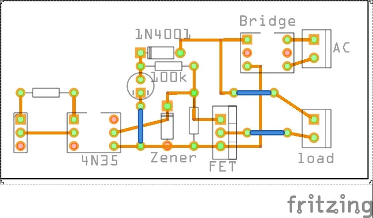
The IRG4PC30 acts as a fast switch that either switches the lamp on or off. It needs about 12 Volt on its gate to do that. The voltage divider R1/R2 should put about 13-15 volts* max on the Gate of the IGBT, switching the lamp fully ON. As there might be some fluctuations on the grid 4k7 is a safe value. If you want to be safe, make sure you have an IGBT with a Base Emmitter breakdown voltage of >= 20 Volt and put a zenerdiode of 15 V parrallel to R2. Possible IGBT's are IRGPC40W or IRG4PC30, but basically any will do provided they have a Base emmitter voltage rating of at least 20 Volts When the optocoupler receives a signal, it opens and pulls the voltage on R1/R2 to zero, effectively closing the IGBT. The PWM signal of an Arduino is faster than the 50Hz Frequency so you will basically see the PWM signal modulated on the 50Hz rectified sine wave, making the effective voltage lower. This circuit is ONLY for incandescant bulbs. It is NOT for any inductive load as it is DC biased. With regard to the capacitor C1, I have tested it with 100uF but will probably work with lower capacity as well.
- Although the average voltage will be 230*0.9, C1 may eventually charge to 310-330 hence 4k7 is a safe value.

Reader acolimitchi pointed out to me that if you add the zener, the 6k8 resistor isnt really necessary anymore, which is true, so the circuit becomes like this:

With regard to MOSFETs vs IGBTs both have their pro's and con's and the voltage and switching rate this circuit is operating under may just be in an overlap of both spectra. Using a MOSFET rather than an IGBT is therefore possible. MOSFETS are generally also cheaper than IGBT's. A tried and tested MOSFET is the STP10NK60Z (Thanks Pavel). This MOSFET has a gate-source breakdown voltage of 30 Volt and has clamping diodes protecting the the gate. Another one that worked quite well is the relatively cheap IRF 730. MOSFETs usually need a bit of a higher voltage than IGBTs to switch so a 6k8 resistor should be fine. If you use a MOSFET without clamping diodes a zener of 15 Volt is adviseable.
I couldnt embed a video, but you will find it here. It is a 60 Watt lamp. The slight flicker you may see when the lamp is turned up, is an artefact. It is caused by my cellphone camera trying to adapt to the changing light intensity
Conclusion: stick to the MOSFET, they are on average 4 times cheaper than IGBT's
BOM:
Bridge rectifier. I used a 1 amp 400 Volt DIL pack 0.25 euro
Diode 1n4001 or 1N4007 0.10 euro
Capacitor 100uF 350-400 Volt 1.36 euro
resistor 100k 0.5-0.6 Watt (actually it dissipates abt 480mW max) 0.12 euro (play it safe with a 1 Watt resistor)
resistor 6k8 1/4 Watt 0.10 euro
Zener 15 Volt 0.5 Watt 0.08 euro
MOSFET IRF730 or STP10NK60 0.58 euro
Optocoupler 4n35 0.25 euro
Resistor between 330ohm-470ohm (possibly even 1k dpending on the Optocoupler) 0.10 euro
So, alltogether at single piece retail prices the cost is 2.94 euro
Step 2: AC PWM Dimmer for Arduino: Thoughts

Without any input signal the lamp will burn at max.
If you notice that When writing a zero PWM value to the circuit the lamp burns a bit less than when you switch off the Arduino, that means that the 4n35 is still opened a bit. Play around with t470 Ohm serial resistor, maybe you need a higher value.
The 100uF 400 Volt can be quite big. A 50 uF may work as well and maybe even a smaller value. However, you do not want the value to be too small thus as not to be able to deliver enough voltage for the Gate of the MosFet in fast switching.
Should you wonder if perhaps you can use a capacitor of a lower voltage -say 25 Volt- and connect that over the zener/6k8 resistor in order to replace the 400 Volt one... maybe that will work, but the 4N35 will make it lose its charge almost instantaneously and due to the large RC time (remember, there is 100k resistor) it might not have time to fully recharge again. At least it will make keep the MOSFET in its resistive phase longer, leading to extra heat development.
The Arduino has a PWM frequency of about 500 Hz. That is ample enough. My guess is that around 100 would be more than enough. The Attiny85 delivers I think 280 Hz on its PWM pins. Software ofcourse can always elevate that if necessary.
This dimmer is not suitable for inductive loads
This dimmer does NOT need zero cross detection.
Heat development:
I tested this with a 60 Watt lamp at full brightness, without any heatsink: the temperature rose with 9 degrees above ambient after half an hour and an hour.
Then I tried with continous dimming from zero to full and back again.: The temperature rose with 10 degrees above ambient after about 10-15 minutes and stayed like that for the hour I tried.
With a 150 Watt halogen spot the temperature went up 15 degrees. It reached max temperature after about 10 minutes and then stayed the same for the hour tested.
This was measured with a DHT11 sensor directly clamped to the MOSFET


