Differential Relief Valves - Winco
Differential Relief Valves - Winco
Differential Relief Valves - Winco

Create successful ePaper yourself
Turn your PDF publications into a flip-book with our unique Google optimized e-Paper software.
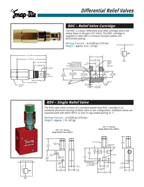
<strong>Differential</strong> <strong>Relief</strong> <strong>Valves</strong>RDC - <strong>Relief</strong> Valve CartridgeThe RDC is a basic differential area relief cartridge which willrelieve flows to 40 gpm (151 l/min). The RDC cartridge issupplied in steel with a corrosion resistant yellow zincdichro mate plating.Working Pressure – to 4,000 psi (276 bar)Weight – Approx. 8 oz. (.23 kg)4.19 (106.4)1.57 (39.8)3.44 (87.4)1.50 ( 38.1)O-RINGSINLET7/8-14NF-2B THDPERFECT TO .69 DEPTHMINOR DIE .814/.798CONCENTRIC TO .754/.750DIA WITHIN .002 TIR.75(19.1)1.16(29.5) INLETIN THISAREA.73MAX DIAOUTLET1.34(34.0)MIN DIA.947 (24.05).942 (23.93)DIA.745 (19.15).750 (19.05)45°OUTLET30°.73 (185)MAX DIA1.0" HEX(25.4)1-1/16 (26.9) HEXBACK-UP RINGS6315°.03(.7).115 (2.92).100 (2.54)63RDV - Single <strong>Relief</strong> ValveThe RDV style valve consists of a standard plated steel RDC cartridge in ananodized aluminum housing of either inline or tee configuration. Standard valves aremanufactured with either NPSF or SAE O-ring sealed porting to 1".Working Pressure – to 4,000 psi (276 bar)Weight – Approx. 1 lb. (.45 kg)3/8", 1/2" PortedSingle <strong>Relief</strong> Valve (RDV)3/4", 1" PortedSingle <strong>Relief</strong> Valve (RDV)2.63(66.8)1-1/16"HEX1-1/16" HEXPRESSUREPORT2 PLACES2.63(66.8).81(20.6)2.50(63.5)PRESSUREPORT3.00(76.2)2.50(63.5).89(22.6)TANKTANKPORT.62(15.7)2.00(50.8).62(15.7)1.25(31.8)MOUNTING HOLE.343 DIA THRU(8.71 DIA)TYP 2 PLACES1.00(25.4)1.50(38.1)3.0(76.2)1.00(25.4).86(21.8)1.15(2.92)2.0(51)
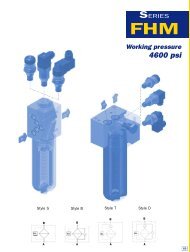
<strong>Differential</strong> <strong>Relief</strong> <strong>Valves</strong>MDD - Dual <strong>Relief</strong> ValveThe MDD style valve features two RDC cartridges in a single housing with standardports from 3/8” to 1" in either NPSF or SAE O-ring sealed threads. A typical applicationfor this type of valve would be shock relief protection for actuator circuits. Pressuresurges on either side of the circuit can be vented to the opposite side throughthe single valve body design.Working Pressure – to 4,000 psi (276 bar)Weight – Approx. 2 lbs. (.91 kg)MOUNTING HOLE.339 DIA THRU(8.61 DIA)TYP 2 PLACESFTHRU PORTTAPPED BOTHSIDESTYP 2 PLACESBAETYPDTYPCHTYP1-1/16 HEX(26.9)G2.66 TYP(67.6)KJPortSizeA B C D E F G H J Kin mm in mm in mm in mm in mm in mm in mm in mm in mm in mm3/8" 2.50 63.5 .22 5.6 2.052 52.1 .80 20.3 1.52 38.6 1.81 46.0 1.69 42.9 .90 22.9 3.50 88.9 1.50 38.11/2" 2.50 63.5 .22 5.6 2.052 52.1 .80 20.3 1.52 38.6 1.81 46.0 1.69 42.9 .90 22.9 3.50 88.9 1.50 38.13/4" 3.00 76.2 .25 6.4 2.500 63.5 .96 24.4 2.08 52.8 1.30 33.0 2.32 58.9 1.00 25.4 3.62 91.9 1.75 44.51" 3.00 76.2 .25 6.4 2.500 63.5 .96 24.4 2.08 52.8 1.30 33.0 2.32 58.9 1.00 25.4 3.62 91.9 1.75 44.5MCD - Dual <strong>Relief</strong> Valve with Make-Up ChecksThe MCD style relief valve is designed with two RDC relief cartridges and two softseated, plated steel, free reverse check valves in a single anodized aluminum body.This valve is best applied in hydraulic circuits where pressure surges are relieved toan unequal volume. These checks prevent cavitation or pressure surge rise byallowing oil to be drawn from the reservoir or relieve to the reservoir in the singlebody design.Working Pressure– to 4,000 psi(276 bar)Weight– Approx. 3 lbs.(1.36 kg)C.38 (9.7).28 (7.1)D9.32 (236.7) APPROXIMATELY4.00 (101.6)ERESERVOIR PORT1/2" NPSFOR 3/8"SAE2.00(50.8)EAB1" HEX(25.4)C3.24 (82.3)THRU PORTS(TAPPED BOTH SIDES).406 DIA MOUNTING HOLESTHRU (10.31) DIA2 PLACESPortSizeA B C D Ein mm in mm in mm in mm in mm1/4" 3.50 88.9 2.00 50.8 1.78 45.2 2.94 74.7 .80 20.33/8" 3.50 88.9 2.00 50.8 1.78 45.2 2.94 74.7 .80 20.31/2" 3.50 88.9 2.00 50.8 1.78 45.2 2.94 74.7 .80 20.33/4" 4.00 101.6 2.00 50.8 2.14 54.4 3.44 87.4 .91 23.11" 4.00 101.6 2.00 50.8 2.14 54.4 3.44 87.4 .91 23.1
<strong>Differential</strong> <strong>Relief</strong> <strong>Valves</strong>Pressure Drop InformationThe curves at the right indicate typical crack and reseatcharacteristics through the standard RDC cartridge based on3 gpm (11 l/min) flow rate, using 175 SSU oil at 100°F (38°C)DIFFERENTIAL PRESSURE (PSI)4000350030002500200015001000FLOW (LPM)0 37.9 75.7 114 15127623820717213810368.9DIFFERENTIAL PRESSURE (BAR)------------- VALVE OPENINGVALVE CLOSING500034.500 10 20 30 40FLOW (GPM)Ordering InformationRELIEF CARTRIDGERELIEF VALVESExample RDC40 — 25 AExample RDV — T 3P — 25 AStyle Max. Flow Pressure SealRange Material<strong>Relief</strong><strong>Differential</strong>Cartridge4040 gpm(151 l/min)15500-1500 psi(35-104 bar)850 psi (59 bar)Std. setting@ 3 gpm (11 l/min)25500-2500 psi(35-172 bar)Std. setting 1500 psi(104 bar) @ 3 gpm(11 l/min)401000-4000 psi(69-276 bar)Std. setting2500 psi (172 bar)@ 3 gpm (11 l/min)All pressures are setat 3 gpm (11 l/min)No letter –Viton (Std)ABuna NEEthylenePropyleneRubberValve <strong>Relief</strong> Thread Pressure SealStyle Adjustment Type Range MaterialRDVSingle<strong>Differential</strong><strong>Relief</strong> ValveMDDDual <strong>Differential</strong><strong>Relief</strong> ValveMCDDual <strong>Differential</strong><strong>Relief</strong> Valvewith make-upchecksTScrewAd just mentNPSF3P = 3/8"4P = 1/2"6P = 3/4"8P = 1"SAE6S = 3/8"8S = 1/2"12S = 3/4"16S = 1"15500-1500 psi(35-104 bar)850 psi (59 bar)Std. setting@ 3 gpm (11 l/min)25500-2500 psi(35-172 bar)Std. setting 1500 psi(104 bar) @ 3 gpm(11 l/min)401000-4000 psi(69-276 bar)Std. setting2500 psi (172 bar)@ 3 gpm (11 l/min)All pressures are setat 3 gpm (11 l/min)No letter –Viton (Std)ABuna NEEthylenePropyleneRubber! WARNING !FAILURE OR IMPROPER SELECTION OR IMPROPER USE OF THE PRODUCTS AND/OR SYSTEMS DESCRIBED HEREIN OR RELATED ITEMS CAN CAUSE DEATH, PERSONAL INJURY AND PROPERTY DAMAGE.This document and other information from Snap-tite, Inc., its subsidiaries and authorized distributors provide product and/or system options for further investigation by users having technical expertise. It isimportant that you analyze all aspects of your application and review the information concerning the product or system in the current product catalog. Due to the variety of operation conditions and applicationsfor these products or systems, the user, through its own analysis and testing, is solely responsible for making the final selection of the products and systems and assuring that all per for mance, safety and warningrequirements of the application are met.The products described herein, including without limitation, product features, specifications, designs, availability and pricing, are subject to change by Snap-tite, Inc. and its subsidiaries at any time with out notice.DISTRIBUTED BY:01-0056BE-1003ISO-9001 Certified