
Developments in Wingtip Vorticity Mitigation Techniques: A Comprehensive Review

1
College of Engineering and Technology, American University of the Middle East, Egaila 54200, Kuwait
2
Center for Turbulence Control, Harbin Institute of Technology (Shenzhen), Shenzhen 518055, China
*
Author to whom correspondence should be addressed.
Aerospace 2024, 11(1), 36; https://doi.org/10.3390/aerospace11010036
Submission received: 22 June 2023
/
Revised: 6 December 2023
/
Accepted: 19 December 2023
/
Published: 29 December 2023
(This article belongs to the Special Issue Vortex Flow Phenomena and Physics of Aerospace Engineering Applications)
Abstract
:Wingtip vortices generated from aircraft wingtips, as a result of the pressure differential at the wingtip, constitute a major component of the total drag force, especially during take-off and landing. In addition to the drag issue, these vortices also pose a significant hazard to smaller aircraft flying in the wake of the larger airplane. The wingtip vortices play a crucial role in aerodynamic efficiency, fuel consumption, flight range, and aircraft stability. This paper presents an overview of the volume of work conducted over the past six decades to encapsulate the phenomena and the techniques devised to mitigate the wingtip vortices. It is shown that the aerodynamic efficiency of the examined wingtip devices ranges from 1% to 15%, depending on the type of wingtips and the flight conditions. Furthermore, it is pointed out that the decrease in fuel consumption ranges from 3.4% to 10%, and the reduction in the induced drag ranges from 5% to 20%.
1. Introduction
Vortices are circular patterns of spinning fluid, and they are generated when an aerodynamic surface with a large span, like the wing of an airplane or the blade of a chopper, moves in a fluid to produce lift. As these vortices often form close to the tips of the lifting surface, they are called wing vortices, wingtip vortices, or trailing vortices. The vortices are characterized by high vorticity levels, extensive areas of strongly spinning fluid, and substantial persistence downstream of the surface. The same characteristics may also prevail in vortices generated from other applications. Thus, a thorough physical understanding is necessary to lead to a range of applications. A comprehensive review is performed in this article, focusing on the fluid dynamics of wingtip vortices in the near field.
1.1. Wingtip Vortices and Their formation
As a byproduct of lift generation, higher pressure below the wing induces the flow to curl about the wingtip in the low-pressure region on the upper surface. The process forms a flow of helical structure known as a wingtip vortex that entrains the wing wake and propagates downstream, as shown in Figure 1. A vortex flow is typically considered a region in a fluid in which the gradient or curl of the velocity components provides vorticity magnitudes and directions, indicating a spiral flow [1,2,3]. Wingtip vortices have an impact on the flight operations of aircraft because of the development of induced drag and turbulence [4]. It is well known that wingtip vortices impact the pressure field near the wing tip where the lifting surface terminates in the fluid [5]. In other words, when the wing generates lift, a net circulation around the wing and in the downstream flow is essentially inevitable [6,7,8].
1.2. Role of Wingtip Vortices in Aerodynamics
Wingtip vortices alter the trajectory of the fluid flow in the wake [10,11,12]. The dynamic behavior of the wingtip not only affects the induced drag forces on the wing [13,14,15] but also creates an undesirable flow structure in the wake of the wing. Researchers have studied this phenomenon with a view to reducing its adverse effects on aircraft safety, fuel consumption, and the structural integrity of aircraft wings. The effects of wingtip vortices on aerodynamic performance are well known in many applications, such as in aeronautical, marine, agricultural, industrial, and environmental science [16,17]. The resultant wingtip vortices, for instance, prolong the durations of take-off, flying, and landing. Moreover, they cause a non-uniform, inhomogeneous flow pattern in the downstream flow when agricultural spraying is performed using an airplane [18]. In marine engineering, wingtip vortices initiate cavitation on the surface of the blades and cause detrimental vibrations [17]. Similarly, vortices are also generated from the finite structures [19,20,21]. The noise generation and energy losses are other demerits of wingtip vortices [22,23,24]. Engineers and scientists have, for many years, been dedicated to discovering methods to alleviate the detrimental impacts of these vortices across a broad spectrum of applications. In the natural world, creatures like owls alter their wingtip feathers in a manner that effectively suppresses wingtip vortices and the accompanying noise [25,26,27,28].
1.3. Control of Wingtip Vortices
The phenomenon of wingtip vortices has captivated researchers for many decades in their attempts to minimize their harmful effects. Researchers have made extensive experimental and theoretical studies [29,30,31,32,33,34,35] as well as numerical investigations [29,35,36,37,38,39,40,41] to understand the characteristics of wing tip vortices. To mitigate the adverse effect of wingtip vorticities, many wingtip devices have been proposed over the years with varying degrees of success. Some of the claimed benefits of these devices are summed up in the following points:
2. History of Wingtip Devices and Some Commercial Applications
A winglet is a device with an airfoil profile affixed to the wing tip that deflects the wingtip vortex away from the lift-producing surface of the wing. Wingtip, on the other hand, is a more general term that refers to any device attached to the wing at its tip. The two terms are sometimes used interchangeably. The use of these devices increases the effective wingspan without making the wings longer. This effect leads to an increase in the left and a reduction in the induced drag but at the expense of increasing the form drag and the aircraft weight. Therefore, if the device is not carefully designed, the increases in the form drag and weight could cancel out any possible improvement in wing efficiency.
The use of wingtip devices to mitigate the adverse effects of wingtip vortices dates back to the 1800s. Lanchester, in 1897, as a pioneer in this field, came up with what is considered the first attempt to use such devices [50]. Based on his theoretical and experimental work, he proposed the use of a wing endplate to reduce wing drag under high lift conditions (Figure 2a). Unfortunately, the reduction in drag was not realized under other flight conditions. The endplate’s success in reducing the induced drag was offset by the increase in friction and interference drag. It soon became obvious that, to reduce these two forms of drag, the wingtip device must have a better aerodynamic shape. In 1952, Sighard Hoerner designed a wingtip that became known as the Hoerner tip [51] (see Figure 2b). Despite the relative success of the Hoerner tip on small aircraft, a significant improvement in drag reduction was not made until the invention of Whitcomb’s winglet device in 1974 [52]. A detailed geometry of Whitcomb’s device can be seen in Figure 3a. The winglet, through a series of wind tunnel tests, showed a reduction in induced drag by 20% and an improvement in the lift-to-drag ratio CL/CD of 9% [50]. One of the first commercial airplanes to use Whitcomb’s winglets was the Learjet 28 in 1977 [53,54], as shown in Figure 3b.
The introduction of the winglet on the Learjet 28 led to a 26% reduction in cruise fuel consumption in comparison to an older model of the same size at the same payload/speed combination. The modifications also improved take-off and landing performance [53]. In recent years, further variants of winglets have been introduced, including fence wingtips, blended wingtips, canted winglets, and raked winglets (Figure 4). Boeing was one of the first airlines to incorporate winglets into one of their major commercial aircraft, the 747-400. The addition of the winglet resulted in a 3% increase in flying range [50]. Aviation Partners Boeing showed a clear improvement in flight range and payload as a result of retrofitting the Boeing 737-800 with winglets [55].
3. Survey of Various Types of Wingtip Devices
In general, wingtip devices can be divided into two categories as shown in Figure 5. Passive devices involve affixing add-on attachments to the wingtip to alter the flow structure around the edge of the wing in such a way that it can reduce the strength of the vortices generated from the wingtip. All the devices mentioned in the previous section fall under this category. Other examples of the passive category reported in the literature include porous wingtips [57,58], ducted wingtips [59], delta wingtips, spiroid winglets [60], slotted wingtips [61], etc.
Figure 6 shows some variations of winglets and wingtip devices reported in the literature. Active devices require an energy source to modify the flow field at the wingtip. Examples of such devices are synthetic jets, plasma actuators, oscillating winglets, etc. In the following sections, we review the research conducted on the main types of wingtip devices and highlight the conclusions drawn at the end of the discussion.
3.1. Passive Wingtip Devices
In this section, passive wingtip devices are listed and the features of each one are explained in detail.
3.1.1. Endplates
As mentioned above, the endplate was first introduced in 1897 by Fredrick W. Lanchester. Since then, several attempts have been made to investigate the effect of endplates on wing performance. Beves et al. [63] carried out an experimental study on the effect of a rectangular endplate (95 mm × 45 mm) mounted on an inverted Tyrrell026 airfoil with a chord length of 0.075 m at a chord-based Reynolds number Rec = 0.5 × 10⁵. They found that the rectangular endplates inhibit spillage flow at the wingtip, thus maintaining a pressure difference between the upper and lower surfaces. When endplates were used, they found that the lift generated was higher and the drag caused by the lift was less. The effect becomes stronger as the lift load increases.
Jung et al. [64] conducted a numerical study on the effect of the endplate on wing performance and vortex structure. They found that the tip vortex moved laterally away from the wing tip when the endplate was used in comparison with the baseline wing, as shown in Figure 7. This led to a 46% increase in CL/CD and a reduction in the induced drag as well as the total drag. It is important to point out that this improvement of the lift-to-drag ratio occurs at the lowest ground clearance during landing and take-off, a phenomenon known as the wing-in-ground (WIG) effect. The substantial in increase in lift-to-drag ratio during this instant is predominately attributed to the increase in lift and is not necessarily accompanied by a reduction in drag. For this reason, it is emphasized that the reported 46% improvement in the lift-to-drag ratio would not necessarily translate to a proportional increase in the flight range.
Gehlert et al. [65] conducted experimental investigations using multi-scale endplates attached to half-wing NACA0012. The results showed that the endplate produced weaker, less coherent vortices which, in turn, resulted in improving the maximum CL/CD by up to 11%. Park et al. [66] conducted a similar numerical investigation on a low-aspect-ratio wing based on the ground effect. They found that the extension of the endplate below the wingtip prevented the escape of the high-pressure air from the bottom surface of the wing, leading to an increase in the lift and reducing the induced drag without an appreciable effect on the total drag.
Wei et al. [67] numerically investigated the influence of a tilted endplate on the performance of wing-in-ground (WIG) crafts at Rec = 6 × 10⁶, solving the incompressible Reynolds-averaged Navier–Stokes equations with the realizable k-ε turbulence model. The study showed that the wingtip vortex structure can be controlled favorably by changing the angle of the endplate in WIG and out-of-ground effect (OGE) flight conditions. It has been noticed that, at a high title angle of the endplate, the wingtip vorticity is forced to shift downward, hence increasing the lift and reducing the induced drag under the ground effect. This provided an improvement in the aerodynamic and economic performance of WIG crafts.
3.1.2. Hoerner-Style Tip
As mentioned in Section 2, in 1952, Sighard Hoerner designed a wingtip device that became commonly known as the ‘Hoerner tip’ [51]. His design was successful in redirecting the core of the wing tip vortex away from the upper surface of the wing. As a result, the wingtip vortex weakened, and the CL/CD enhanced. It has been reported by Met-Co-Aire, a leading manufacturer of wingtips, that the Hoerner tip results in a 1–2% increase in flight range without additional fuel cost [68]. It further reduces the take-off distance, yielding a 10–20% quicker take-off time. A few other advantages were reported such as increased cruise speed and the enhanced overall stability of the aircraft. The Hoerner tip, however, is not without disadvantages. The effectiveness of the device deteriorates at high speeds due to the spillover of the vortex onto the lifting surface. The device is thus more suitable for small aircraft than for large aircraft. For the latter case, winglets are a more viable option.
3.1.3. Half Delta Wingtip (HDW)
Lee et al. [69] employed a NACA 0012 model modified with different configurations of a half-delta wing (HDW) as shown in Figure 8 at Rec = 2.81 × 10⁵. They found that the presence of the HDW causes a significant reduction in axil core velocity with respect to the free stream velocity when compared with the baseline wing as depicted in Figure 9. The reduction in axil core velocity led to an increase in lift and a reduction in the induced drag. By introducing the HDW, Lee and Pereira [69] succeeded in increasing the magnitude lift coefficient from 0.85 to 0.95, a 10% increase in comparison with the baseline wing. However, the results showed that the dynamic stall of the modified wing with a half-delta wing (HDW) occurs at a smaller angle of attack (α ≈ 15°) compared to that (α ≈ 16°) of the baseline wing (BW).
Later, Lu et al. [70] used regular (HDW) and reversed half-delta (HRDW) wingtips to reduce the lift-induced drag during take-off and landing. Their experiments were conducted on the NACA 0012 semi-wing model in a subsonic wind tunnel at Rec = 2.81 × 10⁵. Two configurations of half-delta wingtips were used in their study, each with different variations in the dimensions, namely, s and cr. The letters U and b refer to the upstream air velocity and the length of the wing span, respectively. The results showed that these wingtips result in various degrees of reduction in the tip vortices, which, subsequently, led to a reduction in the lift-induced drag and an increase in the lift. These improvements were attributed to the generation of counterrotating secondary vortices in the vicinity of the ground.
3.1.4. Porous Wingtips
Porous wingtips were investigated by several researchers to determine their effectiveness in reducing the induced drag and improving the aerodynamic efficiency of the wings. Porous wingtips are made by drilling through holes in the wing’s outermost section to bleed air from the pressure surface to the suction surface. Early attempts to experiment with porous wingtips date back to the late 1960s by McCormick et al. [4] and Smith [71]. They showed that adding porous wingtips can significantly increase the core size of the trailing vortices and reduce the tangential velocities.
Scheimm et al. [72], at Rec = 2.6 × 10⁶, carried out wind-tunnel investigations on four different configurations of wingtips, including a porous wingtip. The porous wingtip was realized by affixing a porous plate to the wing tip and aligning it along the wing core. The aim was to study the effect of the wingtips on the characteristics of tip vorticity. The results showed that the porous wingtip caused the area outside the core to be more turbulent but had no effect on shifting the core of the vortices when compared with a plain tip.
Gharbia et al. [57] experimented on a rectangular wing of a NACA66-209 profile with a porous wingtip attached. The used wingtip had 4% porosity which was distributed over an area with a length of 0.6c measured from the trailing edge and a width of 6% of the span measured from the wing edge. The wingtip utilized in the study was created by perforating small through-holes within a region extending 0.6 times the chord length from the trailing edge and spanning a width of 6% of the wing’s total span from the wing’s edge. These drilled holes collectively resulted in a porosity of 4%. The findings indicated a 14% decrease in vorticity strength and a 1.5% enhancement in the CL/CD ratio at moderate angles of attack. The percentage of porosity, the number and sizes of the holes, and the angle at which the holes are drilled can all influence the performance of the porous wingtips, and, hence, they need to be optimized for the best outcome.
Zhang et al. [58], at Rec = 2.5 × 10⁴–2.25 × 10⁵, conducted experiments on porous wingtips with a percentage of porosity ranging from 13% to 50%. The porosities were made by drilling holes of different sizes on two NACA profiles (NACA 0012 and NACA 6412) as shown in Figure 10. Inspired by silent owl wings, they focused on acoustic measurements to investigate the effect of the porous wingtips on reducing the noise level.
3.1.5. Slotted/Serrated Wingtip
Zhang et al. [58] investigated the effect of using serrated wingtips on the level of noise caused by wingtip vortices. This idea was inspired by the silent flight of owls, which is a result of a combination of a few factors [28], one of which is their ability to orient their wingtips into a comb-like shape, as shown in Figure 11. Zhang et al. [58] tested serrated wingtips attached to NACA0012 and NACA4612 at Rec = 2.5 × 10⁴–2.25 × 10⁵ and α = −10°–20°. Despite the useful acoustic data collected, no clear conclusion was drawn about the effectiveness of the serrated wingtips in reducing the noise level in comparison with the baseline case.
Delich et al. [73] studied the effect of a slotted wingtip on induced drag, parasite drag, and vortex structure at Rec = 2.5 × 10⁵ and α = −15°–18°. Different configurations of slotted wingtips were attached to the NACA 0012 wing with an aspect ratio of 4. The results showed that, compared to the solid winglet, slotted winglets typically have a 7.6–14% higher lift coefficient with a penalty of 8–14% induced drag.
Liu et al. [74] reviewed previous studies of birds’ slotted wingtips and proposed some interesting insights into wingtip vortices. The authors cited a study conducted by Tuker on Harris hawks with clipped and unclipped (slotted) wingtips flying freely inside a wind tunnel. The study revealed that the slotted wingtips had a drag reduction of about 70–90%.

3.1.6. Fenced Wingtip
Wingtip fences are made up of two surfaces that extend both above and below the wingtips, as shown in Figure 12. This design was developed by British aerodynamicists at Hatfield and Hertfordshire, UK, and it was more suited to the Airbus wing style. They were first installed on the A310-300 in 1985, saving nearly 5% in fuel costs.
3.1.7. Blended Winglet
A blended winglet is a winglet device that is attached to the plain wing to reduce interference drag. The winglet was invented by Louis Gratzer in the 1990s [77]. Gulfstream pioneered the use of blended winglets on their Gulfstream II airplanes. Blended winglets are commonly used on modern passenger aircraft, such as several 737s, along with 757s and 767s. Khan et al. [60] compared the performance between different types of wingtips, such as blended winglets, spiroid winglets, winglets, and fenced wingtips, for take-off and landing conditions at α = 0°–20°. The blended winglet proved to be the most beneficial design, with a 22% reduction in drag compared with the plain wing. Bravo-Mosquera et al. [78] showed that the blended winglet provides a considerable improvement in aerodynamic efficiency despite a very small increase in the wingspan and wing surface.
3.1.8. Canted Winglet
The canted winglet is very effective in reducing the induced drag and increasing the CL/CD. Abdelghani et al. [79] numerically investigated the effect of using canted wingtips with cant angles of 0°, 30°, and 45° on the performance of a NACA653218 airfoil. The winglet with a canted angle of 45° resulted in a 1.5–3.5% drag reduction while a canted angle of 30° produced a 9–11% enhancement in CL/CD compared with the case without a wingtip.
3.1.9. Sharklets
Starting from 2011, Airbus has integrated the Sharklet wingtips into their aircraft. The sole distinction between the fenced winglets detailed in Section 3.1.6 and the Sharklet wingtip lies in their appearance. These mentioned winglets share such a similar design that there is no superior model between them. Smith et al. [80] demonstrated that using Sharklet wingtips increases the specific air range (km/kgfuel) of up to 2.1% above datum wing fences for all flying phases, partially due to a reduction in inducted-vortex drag by 10.7–11.1%. In another study by M. Marzova [81], it was reported that Sharklet winglets mounted on the Airbus A320 family caused a 4% reduction in emission and an additional 100 nautical miles or 1000 pounds increase in cargo capacity.
3.1.10. Split Scimitar Winglet
Split scimitar winglets, as shown in Figure 13, were developed by Boeing for their 737–800 fleet [82]. The winglets have been named after a type of Middle Eastern sword with a curved blade. The winglet reduces the induced drag by producing a mini co-rotating pair of vortices. These winglets on the B737 Max have resulted in a 5.5% improvement in aerodynamic efficiency, which translates to a 3.3% increase in fuel savings or a 120 km increase in flight range [83].
Cheng et al. [83] investigated three different configurations of split winglets with different half angles between the upper and lower sides of the winglet (45°, 60°, and 75°) as illustrated in Figure 14. Their study concluded that the optimal half angle for split winglets should be between 45° and 75°.
3.1.11. Upswept and Drooped Wingtips
Figure 15 shows the upswept and drooped designs, which are almost identical except for the height parameter. For upswept wings, the height points upwards; meanwhile, for drooped wings, the height points downwards by the same amount. Both surfaces have leading and trailing edges that were tangent to the main wing’s leading and trailing edges [84]. Dhara et al. [85] showed that the concept and development of the Hyper-elliptic Cambered Span (HECS) wing are beneficial, improving aerodynamic efficiency. The HECS wing is used in swept wings to enhance the CL/CD [85].
3.1.12. Spiroid Wingtip
Gratzer [86] described in a US patent numbered 5,120,068 his invention of a spiroid wingtip. The wingtip had an airfoil cross-section and molded into a closed continuous contour of ovular shape when viewed from the airstream direction. The device works by distributing the tip vorticity more uniformly over the trailing edge length, thus avoiding the high concentration of vorticity associated with planar wing tips. As a result, the intensity of the roll-up process is drastically reduced, leading to lower induced drag.
Spiroid wingtips provide a viable method for enhancing the CL/CD of unmanned aerial vehicles (UAVs). However, they may cause detrimental aerodynamic interference in the wing with the wingtip device and degradation in the wing’s aerodynamic performance [87]. There are two varieties of spiroids: the forward spiroid winglet (FWD) and the after spiroid winglet (AFT). Initial testing of the spiroid FWD, conducted on a Gulfstream II aircraft, showed a 10% decrease in fuel consumption.
Inspired by birds’ wingtip feathers during cruise flight, Guerrero et al. [88] numerically studied the effect of a spiroid wingtip on the vortex structure and the aerodynamic performance of the wing. The results showed that, although there was an increase in parasite drag due to the interference between the wing junction and the winglet, the device resulted in an improvement in the aerodynamic performance of the wing by about 7%.
3.1.13. Raked Wingtip
Raked wingtips are designed in such a way that the tip of the wing has a higher degree of sweep compared to the rest of the wing. These types of wingtips are mostly used for aircraft that can fly for ultra-long distances, such as the Boeing 787, Boeing 767, and Boeing 747-800. Raked wingtips work by redirecting wingtip vortices farther outboard and aft of the rest of the wing, and, as a result, they reduce drag and fuel consumption during the cruise segment of the flight.
It is important to highlight that there has been limited literature discussion on the wingtips detailed in Section 3.1.6, Section 3.1.7, Section 3.1.8, Section 3.1.9, Section 3.1.10, Section 3.1.11, Section 3.1.12 and Section 3.1.3. This signifies an opportunity for further research endeavors aimed at enhancing the performance of these specific wingtip designs.
It is also worth mentioning here that none of the passive wingtips work well in all flight conditions. Some types of passive wingtips perform well in take-off and landing conditions but not so well in cruising conditions, and vice versa. For instance, the Hoerner tip works well during take-off and landing but is much less effective during cruise conditions, whereas the raked wingtips behave in the exact opposite way. As a result, Hoerner tips are more common on small and short-range aircraft, while raked wingtips are more common on large, long-range aircraft. Therefore, it soon became apparent to the researchers in the field that, for best performance, the wingtips needed to reshape or act differently as dictated by the flight conditions at hand during the journey. This realization led to the invention of a new category of wingtip devices known as “active wingtips”.
3.2. Active Wingtip Devices
3.2.1. Oscillating Winglet
An oscillating winglet is an active wingtip device that is capable of oscillating about its point of attachment to the base wing. Guha and Kumar [89] experimentally investigated the effect of an oscillating winglet on perturbing the vortex at its onset. The oscillations were induced using piezoelectric Macro Fiber Composite (MFC) while the flow measurements were performed using stereo particle image velocity (SPIV). The experiments were conducted at a Rec = 1.4 × 10⁵ and a wingtip oscillation frequency of 35 Hz. The winglet oscillations led to a sustainable perturbation of the vortex core, vortex diffusion, a 10% reduction in vortex strength, and a 2% reduction in mean circulation. Breitsamter and Allen [90] employed symmetrical and asymmetrical wingtip flaps and observed that the addition of oscillating winglet flaps alters the velocity variations in the core area of the residual vortex and causes distinct narrowband concentrations of turbulent kinetic energy associated with the oscillation frequency.
3.2.2. Folding Wingtip
One solution to improving the aerodynamic efficiency of the aircraft is to increase the wingspan and aspect ratio. However, the increase in the span brings with it new challenges such as withstanding larger peak bending forces; integrating with existing airport infrastructure; and retaining appropriate control authority over the aircraft [91]. A folding wing is a wing structure used to conserve room aboard aircraft carriers and solve the arising issues. Such wingtips were implemented on the Boeing 777X in 2020 with the sole purpose of navigating through the airport’s structure as shown in Figure 16.
Lassen et al. [92] produced a European patent in which they proposed a foldable wingtip for flight control enhancement. Kaygan and Gatto [93] studied folding wingtips for the same purpose. In that study, an off-the-shelf flying wing equipped with a Zagi-type airfoil section served as the foundation of the aircraft. Later, the airplane was modified to have a winglet with a span of 0.15 m added to either side of the wing, which was about 18% of the original span. The scholars numerically studied different types of winglet configurations, including dihedral, twist, and sweep. The findings showed that, if adjustable winglets were used on tiny UAVs, both aircraft control and performance could be improved. To the author’s knowledge, however, there have been no studies on the effect of this kind of wingtips on vortex structure or the induced drag.
3.2.3. Flapping Wingtip
Flapping wingtips represent an active way of influencing wingtip vortex structure and strength. Inspired by birds’ (such as geese’s) flapping wings, many researchers started studying and analyzing the characteristics of the flapping motion. Figure 17 shows an example of a flapping wingtip applied on an AlbatrossOne aircraft. These wingtips, which can freely flap, possess the ability to respond and flex in reaction to wind gusts. This potential offers the capability to reduce wing loads and prevent tip stalls, thereby enhancing overall aircraft performance. To study wingtip vortices during flapping, Qin et al. [94] designed a flapping wing prototype with two-jointed arms to produce a flapping motion. The frequency of the flapping motion varied from fP = 1.0 (Hz) to 2.4 (Hz) while the freestream velocity was maintained at U∞ = 6 (m/s). The flapping changed the wingtip vortex radius and intensity. In comparison with the fixed wing, the results showed that, while the vortex intensity of the flapping wing was much larger in the near-wake region, the vortex of the flapping wings quickly diminished downstream whereas it remained constant for the fixed wing. This decrement was more predominant for larger flapping frequencies. While the flapping wing was an interesting innovation, the mechanism requires an improvement in the flapping control method.
In a low-speed wind tunnel, Muniappan et al. [95] conducted an experiment to determine how the flap angle and frequency affect the lift properties of a flapping wing of a macro air vehicle. The authors found that raising the flap angle and frequency may have a beneficial impact on lift production due to the increase in the angular velocity and the Strouhal number. Azargoon et al. [96] investigated the stall characteristics of flapping wings using a low-speed wind tunnel to simulate real insect flight. Their research revealed that wing corrugations played a significant role in altering the flow regime from laminar to turbulent, thereby delaying stalling and, ultimately, improving aerodynamic performance.
3.2.4. Synthetic Jet Wingtip
Synthetic jets refer to a technique through which air flows through orifices at the wingtip. The airflow could be in the spanwise direction [97] or in the normal direction [98]. These jets are used to disrupt the wingtip vortex structure. Investigations conducted by some researchers such as Margaris et al. [99] and other scholars [100,101,102] have found that the jet flow causes the wingtip vortex core to shift laterally away from the wingtip, effectively increasing the wingspan length and/or generating a counter-rotating vortex pair, which leads to weakening the tip vortex strength. The airflow can be generated using loudspeakers mounted at the base of the wing. The speaker space is connected through a duct that extends in the spanwise direction, from the wing body to the wingtip.
Heyes and Smith [100] experimentally examined the effects of steady blowing and a pulsed jet at pulsing frequencies of 10, 30, and 50 Hz on vortex displacement and changes in the core structure. Their experimental results indicated that the vortex displacement and core structure are functions of the airflow rate from the jet, the pulsing frequency, and the jet slot angle. Using dielectric barrier discharge (DBD) plasma actuators, Hasebe et al. [103] numerically and experimentally investigated the effect of spanwise jets on the wingtip vortex structure, where the actuators were on the suction side of the NACA0012 airfoil. Although the technique led to a reduction in wingtip vortex intensity, it caused an undesirable reduction in CL/CD. Margaris and Gursul [104] conducted experimental studies to attenuate wingtip vorticities using synthetic jets. Velocity measurements at the wingtip and the near-wake region were performed using a PIV system. The blowing synthetic jet effectively diffused the trailing vortex. Holloway and Richardson [105] conducted experiments on NACA 0015 (AR 5) to investigate the effect of spanwise jets on vortex structure. Air was blown through holes in the periphery of the wing cross-section. The jets substantially increased the diameter of the vortex core.
3.2.5. Adaptive Multi-Winglets (Tip Sail)
Multi-winglets consist of small multi-sails attached to the wingtip and have the capability of changing their sail incident and cant angles (Figure 18). This configuration of winglet technology imitates the feathers of a bird. The sails are connected to a moving part so that the cant angle and incidence for each sail can be independently changed. At most angles of attack, the effects of the multi-winglets on the wind drag are negligible. Cosin et al. [106] showed that when α = 0° and 2°, the gadget generates a little bit more drag than the standard wing does. When the angle is increased further, the drag reduction becomes significant, and the overall drag decreases until it stalls. Additionally, the data indicates that the multi-winglets do not alter the primary stall characteristics. Despite minor fluctuations in the stall angle of attack, the separated region remains nearly identical for both the standard wing and the alternative configurations. This consistency is crucial for maintaining consistent tip-stall characteristics, which is essential for safety considerations. Furthermore, it was shown that the winglets reduce the strength of the main wingtip vortex [106].
Reddy et al. [107] found that the layout with several winglets provided a considerable improvement in lift coefficient, diffusing the vortex core more efficiently than other winglet arrangements. The three-element winglet structure used in their model enabled each element to impact the flow pattern created. This caused the vortex to dissipate significantly farther upstream than with other winglet arrangements [107]. Segui et al. [108] conducted a similar study that focused on enhancing aircraft performance during flight through the implementation of an adaptive winglet, applied to the Bombardier Regional Jet CRJ700. The adaptive winglet can move from deflection angles varied from −95 to +95 deg, relative to the spanwise axis. Various winglet deflection angles were tested to cover the typical flight conditions of this aircraft, which includes Mach numbers ranging from 0.31 to 0.79. The outcomes were exceptionally encouraging, resulting in an increase in lift-over-drag ratio by up to 6.10% as a result of moving the winglet from −35 deg to 35 deg on the entire aircraft flight envelope in comparison with a passive winglet fixed at a deflection angle of 73 deg.
Ceron-Muñoz et al. [109] carried out an experimental investigation to analyze the aerodynamic properties of adaptive multi-winglets, referred to as “tip sails”. The objective of this research was to investigate the potential of adaptive tip sails in reducing induced drag by adjusting the tip sail cant angles. The model featured a rectangular wing with a NACA 653-018 airfoil profile. The experiments were conducted at a Reynolds number of 350,000. The results were analyzed with a focus on lift and drag. The findings revealed that it is feasible to determine the optimal configuration of the three winglets to achieve the best possible aerodynamic performance for various flow conditions during climb and cruise.
In another wind tunnel study, Catalano and Ceron-Muñoz [110] examined the influence of an adaptive multi-winglet system on the aerodynamic properties of a low aspect ratio wing. Six main configurations were considered in their studies, known as Conf. 11, Conf. 19, Conf. 40, Conf. 44, Conf. 47, and Conf. 48. Figure 18 shows Conf. 11 based on the angle of winglets. The authors found that combining the configurations of three winglets could improve the aerodynamic properties of a wing.
The configurations of the multi-winglets were defined as the functions of the angles of three winglets with angles of A, B, and C (Figure 18). To be consistent with the published studies [110], the examined test cases associated with Figure 18 are shown in Table 1.
Furthermore, the authors have investigated the effect of the adaptive wingtip shown in Figure 18 on turbulence intensity [110]. It was found that the size of the wing wake does not change significantly for the case without multi-winglets. Moreover, they found that the tip-tank wake has the biggest impact on the magnitude of the wake at the tip. However, there was a small decrease in the turbulence’s intensity in the vicinity of the tip-tank, suggesting that roll-up may be less frequent. The results of turbulence intensity are shown in Figure 19.
Another example of adaptive wingtips being used to reduce the induced drag was proposed by Guerrero et al. [62]. Their approach was to propose variable cant angle winglets which could potentially allow aircraft to achieve the best all-around performance in terms of lift-induced drag reduction throughout the flight envelope. The investigation was carried out using CFD simulation at Mach numbers of 03 and 0.84 and different angle-of-attack values. The findings indicate that careful control of the winglet cant angle can lead to significant reductions in drag for a given lift value, both at high and low Mach numbers. Furthermore, it was observed that the use of variable cant angle winglets does not have a negative impact on stall behavior. In a separate CFD investigation, the same researchers [111] explored the influence of the sweep angle on aerodynamic performance at a fixed cant angle. Their results demonstrated that introducing a sweep angle to the winglet positively impacts the overall aerodynamic performance of the wing. This effect can be attributed to the fact that higher sweep angles result in reduced parasite drag. Additionally, at high Mach numbers, the sweep angle plays a role in reducing wave drag, further contributing to drag reduction.
3.2.6. ATLAS Active Winglets
The Active Load Alleviation System (ATLAS) Winglet, developed by Tamarack Aerospace Group [112], exhibits a remarkable capability to autonomously adjust wing loading during load events. This adaptive technology, as shown in Figure 20, employs load sensors and a responsive camber surface, and enhances aerodynamic efficiency without requiring pilot intervention or additional wing structure. Furthermore, its ‘bolt-on’ installation feature, coupled with a patented amalgamation of these elements, bestows upon active winglets a substantial two-to-three-fold performance advantage over passive winglets. Such enhancements include an extended range, faster climb, significant fuel savings of about 33% as claimed by the manufacturer [113], increased weight limits, and improved useful load, among other benefits.
As evident from the preceding discussion in this article, the majority of the research has relied on experimental work. Nonetheless, it is essential to highlight that computational studies have significantly contributed to enhancing aircraft performance. Delavenne et al. [114] considered the wing flexibility and the impact of the winglet on the wing shape on aerodynamic predictions using different models. High-fidelity CFD/CSM computations have been studied to minimize the drag and wing root bending moment. The study resulted in a drag reduction of 4% and 0.8% fuel saving with a limited 2% increase in the wing root bending moment. In a different study, Delavenne et al. [115] investigated the influence of cant angle deflections on flutter characteristics. They have also studied the effect of the hinge line location and its orientation with respect to the longitudinal axis of the aircraft. The study demonstrated that the active winglet could result in drag reductions to around 1%. The orientation of the hinge mainly impacted loads but to a far lesser extent compared to the spanwise direction.
Babigian et al. [116] conducted an analysis of the vortices generated by winglets on aircraft wingtips, employing a three-dimensional approach with the Fluent computational fluid dynamics software (FLUENT, ver. 6.3.26) and the Spalart–Allmaras turbulence model. Their investigation revealed a notable reduction in vortex formation at the wingtips of a moving aircraft. In a similar study, Mattos et al. [117] investigated the impact of winglets installed on the wingtip of an Embraer 170 model airplane, employing a three-dimensional Fluent analysis. Their findings indicated a substantial 4.5% reduction in the total drag force attributable to the incorporation of winglets.
Furthermore, Yahaya et al. [118] undertook a comprehensive examination of the flow patterns around Whitcomb winglets, combining both numerical simulations and experimental analyses at a Reynolds number of 2.33 × 10⁶. They relied on Fluent-based methods for their analysis, which demonstrated a reduction in vortex formation around the Whitcomb winglets compared to the wingtips without winglets, consequently reducing induced drag. Narayan and John [119], in their study, investigated the formation and distribution of vortices at the wingtips of wingleted wings using Ansys Fluent, incorporating the k–ω Shear Stress Transport (SST) turbulence model. Their focus was on evaluating the aerodynamic performance during flight, expressed as the Lift-to-Drag (L/D) ratio. Their results showcased a significant 3.54% enhancement with blended winglets, a substantial 14.81% improvement with BMAX, an impressive 11.03% increase with Multi-Tip-2, a substantial 22.59% boost with Multi-Tip-3, and a noteworthy 20.24% enhancement with Multi-Tip-4.
Based on the key wingtip criteria emphasized in this paper, such as aerodynamic efficiency, induced drag reduction, fuel consumption, and increased flight range (refer to Figure 21), our assessment positions fuel consumption as the most critical metric among these factors. Upon closer examination of various metrics, it is evident that the spiroid wingtip emerges as one of the optimal wingtip designs meeting these criteria, notably excelling in terms of fuel consumption. Moreover, sharklets rank second after spiroid wingtips, delivering commendable performance not only in fuel consumption but also demonstrating favorable performance in mitigating induced drag.
4. Summary and Conclusions
In this study, a significant volume of research over the last sixty years is reviewed. Particular attention is paid to the concept of wingtip vortices, the early history of wingtip devices, and the development of these devices throughout several decades. Wingtip devices have typically fallen into two classifications: passive and active. The predominant wingtips employed in commercial settings have been of the passive variety such as sharklets, raked wingtips, and split scimitar winglets.
Over the past several years, there has been a surge in research on active wingtips that can be manipulated to yield the best performance for the given flight condition and, consequently, make the airplane more aerodynamically efficient and stable. Some of the active wingtips proposed in the past are oscillating winglets, folding winglets, synthetic jet wingtips, flapping winglets, and adaptive multi-winglets.
Table 2 shows a summary of the studies on passive and active wingtips. It highlights the major effects of passive wingtips on vortex strength, aerodynamic efficiency, fuel consumption, flight range, and induced drag. The available data collected from the literature are summarized, focusing on the effects of wingtips on forces, flight conditions, and CL/CD.
Figure 21 provides a visual representation of the improvement caused by the wingtip devices, in aerodynamic efficiency, fuel consumption, induced drag, and flight range. Porous wingtips result in the highest aerodynamic efficiency (around 14%) while fenced wingtips produce the least (around 2%). Raked and sharklet wingtips achieve an acceptable aerodynamic efficiency of 8% and 9%, respectively (Figure 21a). Figure 21b demonstrates that the highest reduction of 9.8% in fuel consumption is attained using the spiroid wingtip, which is five times more effective than raked wingtips. The high fuel consumption of the racked wingtip could be attributed to the high induced drag in comparison with the spiroid tip (Figure 21c). The blended winglet, as shown in Figure 21d, is reported to have the highest flight range. It is to be noted here that these graphs are meant to give a summary of the values reported in the literature and are not meant for direct comparison among the wingtips. Such a comparison would be difficult due to the difference in the evaluation tools and the conditions in which these studies were performed.
It would have been intriguing to conduct a comparison regarding the various wingtip designs in terms of their manufacturing cost. Regrettably, there is a notable scarcity of information available in the existing literature addressing this aspect. The sole exception to this lack of data may be found in a New York Times article, which cites Captain Joel Booth, the Managing Director of Operations Planning and Fuel Efficiency at United Airlines [134]. He provided insights into the cost associated with outfitting Boeing 737 aircraft with winglets. According to the report, the cost of winglets for large airplanes ranges from USD 500,000 to USD 2 million. Furthermore, he anticipated that the return-on-investment period could be approximately two years, contingent upon fluctuations in fuel prices and the number of flights.
In conclusion, we have reviewed a considerable volume of research work conducted over the last six decades, focusing on the theory of wingtip vortices, the early history of wingtip devices, and the latest developments of these devices in recent years. These devices are classified as passive and active. The majority of the wingtips in commercial applications are passive types, including winglets, sharklets, raked wingtips, and split scimitar winglets. Active device research has gained popularity in recent years. This interest was prompted by the quest to develop wingtips for the different flight conditions of the airplane and to improve the aerodynamic efficiency and the airplane’s stability. Some of the active wingtips featured in the literature include oscillating winglets, folding wingtips, pulsed jet wingtips, flapping wingtips, and adaptive multi-winglets. It is important to note that, since the active wingtips are designed to adjust to varying flight conditions, they are anticipated to deliver superior aerodynamic performance when compared to their passive counterparts. However, this enhanced performance comes at a considerable cost. While there is a lack of readily available manufacturing cost data in the literature, it is reasonable to assume that active wingtips would incur higher expenses due to the necessary mechanisms required to make them adaptive, as well as the subsequent maintenance costs.
Overall, the examined wingtip devices achieved varying levels of success, with improvements in aerodynamic efficiency ranging from 1% to 15%, reductions in fuel consumption ranging from 3.4% to 10%, and decreases in induced drag ranging from 5% to 20%. The extent of these improvements depended on the specific types of wingtips and the prevailing flight conditions.
Regarding the future prospects of these devices, it appears that passive wingtips may have reached their maximum potential, with research in this area having reached a certain level of saturation. In contrast, active wingtips are a relatively recent development and are still primarily confined to research laboratories at the moment. Commercial applications of active wingtips in the aviation industry have yet to materialize. Therefore, we anticipate more research and development related to active wingtips in the future.
Funding
This research received no external funding.
Conflicts of Interest
The authors declare that they have no conflicts of interest.
Nomenclature
| Latin Alphabet | |
| c | Chord length |
| CD | Drag coefficient |
| CL | Lift coefficient |
| D | Drag |
| Di | Induced drag |
| fP | frequency of flapping motion |
| L | Lift |
| Re | Reynolds number |
| u | Time–mean velocity |
| U∞ | Free stream velocity |
| x | Stream-wise coordinate |
| (x, y) | Coordinate system |
| Greek Alphabet | |
| α | Angle of attack, degree |
| Acronym | |
| AR | Aspect ratio |
| BW | Baseline wing |
| CFD | Computational Fluid Dynamic |
| DBD | Dielectric Barrier Discharge |
| DDES | Delayed Detached-Eddy Simulation |
| DNS | Direct Numerical Simulation |
| HDW | Half Delta Wingtip |
| HRDW | reversed half-delta wingtips |
| LES | Large Eddy Simulation |
| LSA | Linear Stability Analysis |
| NACA | National Advisory Committee for Aeronautics |
| FVM | Finite volume method |
| MFC | Macro Fibber Composite |
| PLT | Prandtl lifting-line theory |
| PIV | Particle Image Velocimetry |
| RANS | Reynolds-Averaged Navier–Stokes |
| RSM | Reynolds stress equation model |
| SAT | Spalart–Allmaras Turbulence |
| SRS | Scale-Resolving Simulation |
| SPIV | Stereo Particle Image Velocity |
| UAV | Unmanned Aerial Vehicles |
| HECS | Hyper Elliptic Cambered Span |
References
- Bhatt, R.; Alam, M.M. Vibrations of a square cylinder submerged in a wake. J. Fluid Mech. 2018, 853, 301–332. [Google Scholar] [CrossRef]
- Wang, L.; Alam, M.M.; Rehman, S.; Zhou, Y. Effects of blowing and suction jets on the aerodynamic performance of wind turbine airfoil. Renew. Energy 2022, 196, 52–64. [Google Scholar] [CrossRef]
- Zheng, Q.; Alam, M.M. Intrinsic features of flow past three square prisms in side-by-side arrangement. J. Fluid Mech. 2017, 826, 996–1003. [Google Scholar] [CrossRef]
- McCormick, B.W.; Tangler, J.L.; Sherries, H.E. Structure of trailing vortices. J. Aircr. 1968, 5, 260–267. [Google Scholar] [CrossRef]
- Green, S.I. Fluid Vortices; Springer: Berlin/Heidelberg, Germany, 1995. [Google Scholar]
- Bertin, J.J.; Smith, M.L. Aerodynamics for Engineers-Second Edition. Aeronaut. J. 1991, 259, 19–99. [Google Scholar]
- Wang, S.; Zhou, Y.; Alam, M.M.; Yang, H. Turbulent intensity and Reynolds number effects on an airfoil at low Reynolds numbers. Phys. Fluids 2014, 26, 115107. [Google Scholar] [CrossRef]
- Wang, L.J.; Alam, M.M.; Zhou, Y. Experimental Study of a Passive Control of Airfoil Lift Using Bioinspired Feather Flap. In Lecture Notes in Mechanical Engineering; Springer: Berlin, Germany, 2021; pp. 39–44. [Google Scholar] [CrossRef]
- Martin, S. 5 Factors That Affect the Strength of Wingtip Vortices|Boldmethod. Boldmethod. 2017. Available online: https://www.boldmethod.com/blog/lists/2017/02/5-factors-that-affect-vortex-strength/ (accessed on 8 March 2023).
- Zhang, Z.; Ji, C.; Xu, D.; Zhu, H.; Derakhshandeh, J.F.; Chen, W. Effect of yaw angle on vibration mode transition and wake structure of a near-wall flexible cylinder. Phys. Fluids 2022, 34, 077106. [Google Scholar] [CrossRef]
- Alam, M.M.; Zheng, Q.; Derakhshandeh, J.F.; Rehman, S.; Ji, C.; Zafar, F. On forces and phase lags between vortex sheddings from three tandem cylinders. Int. J. Heat Fluid Flow 2018, 69, 117–135. [Google Scholar] [CrossRef]
- Derakhshandeh, J.F. Analysis of wake induced vibration of a coupled circular cylinder-piezoelectric using two-way fluid structural interaction. Appl. Ocean Res. 2022, 121, 103116. [Google Scholar] [CrossRef]
- Birch, D.; Lee, T.; Mokhtarian, F.; Kafyeke, F. Structure and induced drag of a tip vortex. J. Aircr. 2004, 41, 1138–1145. [Google Scholar] [CrossRef]
- Céron-Muñoz, H.D.; Cosin, R.; Coimbra, R.F.F.; Correa, L.G.N.; Catalano, F.M. Experimental investigation of wing-tip devices on the reduction of induced drag. J. Aircr. 2013, 50, 441–449. [Google Scholar] [CrossRef]
- Bowers, A.H.; Murillo, O.J.; Jensen, R.R.; Eslinger, B.; Gelzer, C. On Wings of the Minimum Induced Drag: Spanload Implications for Aircraft and Birds; Nasa/Tp—2016–219072; NASA: Washington, DC, USA, 2016; pp. 1–22.
- Giuni, M. Formation and Early Development of Wingtip Vortices; University of Glasgow: Glasgow, UK, 2013. [Google Scholar]
- Arndt, R.E.A. Cavitation in vortical flows. Annu. Rev. Fluid Mech. 2002, 34, 143–175. [Google Scholar] [CrossRef]
- Drummond, A.M.; Onno, R.; Panneton, B. Trajectories and Stability of Trailing Vortices Very Near the Ground; National Research Counccil Canada: Ottawa, ON, Canada, 1991. [Google Scholar]
- Rastan, M.R.; Shahbazi, H.; Sohankar, A.; Alam, M.M.; Zhou, Y. The wake of a wall-mounted rectangular cylinder: Cross-sectional aspect ratio effect. J. Wind Eng. Ind. Aerodyn. 2021, 213, 104615. [Google Scholar] [CrossRef]
- Zhao, C.; Wang, H.; Zeng, L.; Alam, M.M.; Zhao, X. Effects of oncoming flow turbulence on the near wake and forces of a 3D square cylinder. J. Wind Eng. Ind. Aerodyn. 2021, 214, 104674. [Google Scholar] [CrossRef]
- Rastan, M.R.; Sohankar, A.; Alam, M.M. Low-Reynolds-number flow around a wall-mounted square cylinder: Flow structures and onset of vortex shedding. Phys. Fluids 2017, 29, 103601. [Google Scholar] [CrossRef]
- Glegg, S.A.L. Prediction of blade wake interaction noise based on a turbulent vortex model. AIAA J. 2012, 29, 1545–1551. [Google Scholar] [CrossRef]
- Greenblatt, D. Fluidic control of a wing tip vortex. AIAA J. 2012, 50, 375–386. [Google Scholar] [CrossRef]
- Noda, R.; Nakata, T.; Senda, K.; Liu, H. Development of Microstructured Low Noise Propeller for Aerial Acoustic Surveillance. In Proceedings of the 2021 IEEE/SICE International Symposium on System Integration (SII), Iwaki, Japan, 11–14 January 2021; pp. 482–486. [Google Scholar] [CrossRef]
- Gruschka, J.G.; Borchers, H.D.; Coble, I.U. Aerodynamic noise produced by a gliding owl. Nature 1971, 233, 409–411. [Google Scholar] [CrossRef]
- Ortega, C.P. Chapter 2: Effects of noise pollution on birds: A brief review of our knowledge. Source Ornithol. Monogr. Ornithol. Monogr. 2012, 74, 6–22. [Google Scholar] [CrossRef]
- Greenewalt, C.H. The flight of birds: The significant dimensions, their departure from the requirements for dimensional similarity, and the effect on flight aerodynamics of that departure. Trans. Am. Philos. Soc. 1975, 65, 1–67. [Google Scholar] [CrossRef]
- Sarradj, E.; Fritzsche, C.; Geyer, T.; Gutmark, E. Silent OWL flight: Bird flyover noise measurements. AIAA J. 2011, 49, 769–779. [Google Scholar] [CrossRef]
- Dacles-Mariani, J.; Zilliac, G.G.; Chow, J.S.; Bradshaw, P. Numerical/experimental study of a wingtip vortex in the near field. AIAA J. 1995, 33, 1561–1568. [Google Scholar] [CrossRef]
- Chow, J.S. Turbulence Measurements in the Near-Field of a Wingtip Vortex; Stanford University: Stanford, CA, USA, 1994. [Google Scholar]
- Chow, J.S.; Zilliac, G.G.; Bradshaw, P. Mean and turbulence measurements in the near field of a wingtip vortex. AIAA J. 1997, 35, 1561–1567. [Google Scholar] [CrossRef]
- Stinebring, D.B.; Farrell, K.J.; Billet, M.L. The structure of a three- dimensional tip vortex at high reynolds numbers. J. Fluids Eng. Trans. ASME 1991, 113, 496–503. [Google Scholar] [CrossRef]
- Devenport, B.W.J.; Rife, M.C. The structure and development of a wing-tip vortex. J. Fluid Mech. 1996, 312, 67–106. [Google Scholar] [CrossRef]
- Anderson, E.; Wright, C. Experimental study of the structure of the wingtip vortex. In Proceedings of the 38th Aerospace Sciences Meeting and Exhibit, Reno, NV, USA, 10–13 January 2000; p. 269. [Google Scholar]
- Mishra, N.; Gupta, A.S.; Dawar, J.; Kumar, A.; Mitra, S. Numerical and Experimental Study on Performance Enhancement of Darrieus Vertical Axis Wind Turbine With Wingtip Devices. J. Energy Resour. Technol. 2018, 140, 121201. [Google Scholar] [CrossRef]
- Srinivasan, G.R.; McCroskey, W.J.; Baeder, J.D.; Edwards, T.A. Numerical simulation of tip vortices of wings in subsonic and transonic flows. AIAA J. 1988, 26, 1153–1162. [Google Scholar] [CrossRef]
- Dacles-Mariani, J.; Rogers, S.; Kwak, D.; Zilliac, G.; Chow, J. A computational study of wingtip vortex flowfield. In Proceedings of the 23rd Fluid Dynamics, Plasmadynamics, and Lasers Conference, Orlando, FL, USA, 6–9 July 1993; p. 3010. [Google Scholar]
- Dacles-Mariani, J.; Kwak, D.; Zilliac, G. On numerical errors and turbulence modeling in tip vortex flow prediction. Int. J. Numer. Methods Fluids 1999, 30, 65–82. [Google Scholar] [CrossRef]
- Lombard, J.E.W.; Moxey, D.; Sherwin, S.J.; Hoessler, J.F.A.; Dhandapani, S.; Taylor, M.J. Implicit large-eddy simulation of a wingtip vortex. AIAA J. 2016, 54, 506–518. [Google Scholar] [CrossRef]
- Pereira, F.S.; Eça, L.; Vaz, G. Simulation of wingtip vortex flows with reynolds-averaged navier-Stokes and scale-resolving simulation methods. AIAA J. 2019, 57, 932–948. [Google Scholar] [CrossRef]
- García-Ortiz, J.H.; Domínguez-Vázquez, A.; Serrano-Aguilera, J.J.; Parras, L.; del Pino, C. A complementary numerical and experimental study of the influence of Reynolds number on theoretical models for wingtip vortices. Comput. Fluids 2019, 180, 176–189. [Google Scholar] [CrossRef]
- Spillman, J.J.; Ratcliffe, H.Y.; McVitie, A. Flight Experiments To Evaluate the Effect of Wing-Tip Sails on Fuel Consumption and Handling Characteristics. Aeronaut. J. 1979, 83, 279–281. [Google Scholar] [CrossRef]
- Wu, M.; Shi, Z.; Xiao, T.; Ang, H. Effect of wingtip connection on the energy and flight endurance performance of solar aircraft. Aerosp. Sci. Technol. 2021, 108, 106404. [Google Scholar] [CrossRef]
- Balatti, D.; Khodaparast, H.H.; Friswell, M.I.; Manolesos, M.; Amoozgar, M. The effect of folding wingtips on the worst-case gust loads of a simplified aircraft model. Proc. Inst. Mech. Eng. Part G J. Aerosp. Eng. 2022, 236, 219–237. [Google Scholar] [CrossRef]
- Patil, M.J.; Hodges, D.H.; Cesnik, C.E.S. Nonlinear aeroelasticity and flight dynamics of high-altitude long-endurance aircraft. J. Aircr. 2001, 38, 88–94. [Google Scholar] [CrossRef]
- Imamura, T.; Enomoto, S.; Yamamoto, K. Noise simulation around NACA0012 wingtip using large eddy simulation. Trans. Jpn. Soc. Aeronaut. Space Sci. 2012, 55, 214–221. [Google Scholar] [CrossRef]
- Klei, C.E.; Buffo, R.M.; Stumpf, E. Effects of wing tip shaping on noise generation. In Proceedings of the INTERNOISE 2014—43rd International Congress on Noise Control Engineering, Melbourne, Australia, 16–19 November 2014; pp. 1–10. [Google Scholar]
- Snyder, M.P.; Weisshaar, T.A. Flutter and directional stability of aircraft with wing-tip fins: Conflicts and compromises. J. Aircr. 2013, 50, 615–625. [Google Scholar] [CrossRef]
- Bushnell, D.M. Potential Impact of Advanced Aerodynamic Technology on Air Transportation System Productivit; Memorandum 109154; NASA Tech: Washington, DC, USA, 1994.
- Bargsten, C.J.; Gibson, M.T. NASA Innovation in Aeronautics: Select Technologies that have Shaped Modern Aviation; NASA Tech: Washington, DC, USA, 2011.
- Hoerner, S. Aerodynamic Shape of the Wing Tips; USAF Technical Reports Engineering Division Air Materiel Command; United States Air Force Arch; The De Havilland Aircraft of Canada Limited, Technical Report No. 5752; Wright-Patterson Air Force Base: Dayton, OH, USA, 1952. [Google Scholar]
- Whitcomb, R.T. A Design Approach and Selected Wind Tunnel Results at High Subsonic Speeds for Wing-Tip Mounted Winglets; NASA Technical Note No. TN D-8260; NASA: Washigton, DC, USA, 1976.
- Reynolds, P.T. The Learjet “Longhorn” Series—The First Jets with Winglets; Section 3: 790527–790858 (1979); SAE Transactions: New York, NY, USA, 1979; Volume 88, pp. 2034–2038. [Google Scholar]
- Padfield, R. Historic Learjet 28 Flies Again—Aviation International News. 2013. Available online: https://www.ainonline.com/aviation-news/galleries/historic-learjet-28-flies-again (accessed on 9 March 2023).
- Eickmann, K.E. Assessment of Wingtip Modifications to Increase the Fuel Efficiency of Air Force Aircraft; National Academies Press: Washonton, DC, USA, 2007. [Google Scholar] [CrossRef]
- Siddiqui, N.A.; Asrar, W.; Sulaeman, E. Literature review: Biomimetic and conventional aircraft wing tips. Int. J. Aviat. Aeronaut. Aerosp. 2017, 4, 6. [Google Scholar] [CrossRef]
- Gharbia, Y.A.; Hussain, Z.; Arshad, A. Effect of Porous Wing Tip on Wing Performance and Vortex Strength. In Proceedings of the 2nd International Symposium on Aeronautical Science and Technology, Jakarta, Indonesia, 24–27 June 1996. [Google Scholar]
- Zhang, T.; Moreau, D.; Geyer, T.; Fischer, J.; Doolan, C. Dataset on tip vortex formation noise produced by wall-mounted finite airfoils with sinusoidal and porous tip geometries. Data Br. 2020, 30, 105471. [Google Scholar] [CrossRef]
- Gharbia, Y.A.; Arshad, S.A.; Husain, Z. Improvment of Wing Performance and Vortex Structure Using Wing-tip Devices. In Proceedings of the 3rd International Symposium on Aerothermodynamics and Internal Flow, Beijing, China, 1–6 September 1996. [Google Scholar]
- Khan, F.N.; Batul, B.; Aizaz, A. A CFD Analysis of Wingtip Devices to Improve Lift and Drag Characteristics of Aircraft Wing. IOP Conf. Ser. Mater. Sci. Eng. 2019, 642, 012006. [Google Scholar] [CrossRef]
- Samal, S.K.; Dash, P.K. Effect of Slotted Wing Tip on Aerodynamic Efficiency. Test Eng. Manag. 2020, 83, 17204–17212. [Google Scholar]
- Guerrero, J.E.; Sanguineti, M.; Wittkowski, K. Variable cant angle winglets for improvement of aircraft flight performance. Meccanica 2020, 55, 1917–1947. [Google Scholar] [CrossRef]
- Beves, C.C.; Barber, T.J. The Wingtip Vortex of a Dimpled Wing with an Endplate. J. Fluids Eng. Trans. ASME 2017, 139, 021202. [Google Scholar] [CrossRef]
- Jung, J.H.; Kim, M.J.; Yoon, H.S.; Hung, P.A.; Chun, H.H.; Park, D.W. Endplate effect on aerodynamic characteristics of threedimensional wings in close free surface proximity. Int. J. Nav. Archit. Ocean Eng. 2012, 4, 477–487. [Google Scholar] [CrossRef]
- Gehlert, P.; Cherfane, Z.; Cafiero, G.; Vassilicos, J.C. Effect of Multiscale Endplates on Wing-Tip Vortex. AIAA J. 2021, 59, 1614–1628. [Google Scholar] [CrossRef]
- Park, K.; Lee, J. Influence of endplate on aerodynamic characteristics of low-aspect-ratio wing in ground effect. J. Mech. Sci. Technol. 2008, 22, 2578–2589. [Google Scholar] [CrossRef]
- Wei, Y.; Yang, Z. Aerodynamic investigation on tiltable endplate for WIG craft. Aircr. Eng. Aerosp. Technol. 2012, 84, 4–12. [Google Scholar] [CrossRef]
- Texas Aeroplastics. The Story Behind The Hoerner Wing Tip. Available online: https://texasaeroplastics.com/pages/the-story-behind-the-hoerner-wing-tip (accessed on 17 December 2023).
- Lee, T.; Pereira, J. Modification of static-wing tip vortex via a slender half-delta wing. J. Fluids Struct. 2013, 43, 1–14. [Google Scholar] [CrossRef]
- Lu, A.; Lee, T. Passive Wingtip Vortex Control by Using Tip-Mounted Half Delta Wings in Ground Effect. J. Fluids Eng. Trans. ASME 2020, 142, 021201. [Google Scholar] [CrossRef]
- Smith, H.C. Effects of a Porous Wingtip on an Aircraft Trailing Vortex. Master’s Thesis, Pennsylvania State University, State College, PA, USA, 1967. [Google Scholar]
- Scheimm, J.; Shivers, J.P. Exploratory Investigation of the Structure of the Tip Vortex of a Semispan Wing For—Several Wing-Tip Modifications; NASA Technical Note D-6101; National Aeronautics and Space Administration: Washington, DC, USA, 1971.
- Deslich, J.; Gunasekaran, S. Effect of slotted winglet on the wingtip vortex. In Proceedings of the AIAA Aviation 2019 Forum, Dallas, TX, USA, 17–21 June 2019; pp. 1–20. [Google Scholar] [CrossRef]
- Liu, D.; Song, B.; Yang, W.; Yang, X.; Xue, D.; Lang, X. A Brief Review on Aerodynamic Performance of Wingtip Slots and Research Prospect. J. Bionic Eng. 2021, 18, 1255–1279. [Google Scholar] [CrossRef]
- Gehlert, P.; Sabnis, K.; Babinsky, H. Effect of Winglet Serration Geometry on the Wingtip Vortex. In Proceedings of the AIAA SCITECH 2022 Forum, San Diego, CA, USA, 3–7 January 2022. [Google Scholar] [CrossRef]
- Mariofan. Wingtip Fence Airbus A320. 2014. Available online: https://commons.wikimedia.org/wiki/File:Wingtip_Fence_Airbus_A320.JPG (accessed on 18 July 2022).
- Gratzer, L.B. Blended Winglet. US Patent 5,348,253, 1 February 1993. [Google Scholar]
- Bravo-Mosquera, P.D.; Vaca-Rios, J.J.; Diaz-Molina, A.I.; Amaya-Ospina, M.A.; Cerón-Muñoz, H.D. Design and aerodynamic evaluation of a medium short takeoff and landing tactical transport aircraft. Proc. Inst. Mech. Eng. Part G J. Aerosp. Eng. 2022, 236, 825–841. [Google Scholar] [CrossRef]
- Abdelghany, E.S.; Khalil, E.E.; Abdellatif, O.E.; Elhariry, G. Air craft winglet design and performance: Cant angle effect. In Proceedings of the 14th International Energy Conversion Engineering Conference, Salt Lake City, UT, USA, 25–27 July 2016. [Google Scholar] [CrossRef]
- Smith, D.D.; Ajaj, R.M.; Isikveren, A.T.; Friswell, M.I. Multi-objective optimization for the multiphase design of active polymorphing wings. J. Aircr. 2012, 49, 1153–1160. [Google Scholar] [CrossRef]
- Mrazova, M. Innovations, Technology and Efficiency Shaping the Aerospace Environment. Incas Bull. 2013, 5, 91–99. [Google Scholar] [CrossRef]
- Flydubai Introduces Split Scimitar® Winglets on its Next-Generation Boeing 737–800 Fleet. Biz Today News. 2019. Available online: https://www.biztoday.news/2019/10/04/flydubai-introduces-split-scimitar-winglets-on-its-next-generation-boeing-737-800-fleet/ (accessed on 17 December 2023).
- Cheng, Z.; Wu, Y.; Xiang, Y.; Liu, H.; Wang, F. Benefits comparison of vortex instability and aerodynamic performance from different split winglet configurations. Aerosp. Sci. Technol. 2021, 119, 107219. [Google Scholar] [CrossRef]
- Rajendran, S. Design of Parametric Winglets and Wing Tip Devices—A Conceptual Design Approach. Ph.D. Thesis, Linkoping Univerity, Likoping, Sweden, 2012. [Google Scholar]
- Dhara, A.; Ubhi, K.S.; Kumari, P.; Purewal, R.K. A Systematic Review of Morphing Wing in Aviation Industry. J. Emerg. Technol. Innov. Res. 2022, 9, 557–563. [Google Scholar]
- Gratzer, L.B. Spiroid-Tipped Wing. U.S. Patent 5,102,068, 7 April 1992. [Google Scholar]
- Kravchenko, I.F.; Loginov, V.V.; Ukrainets, Y.O.; Hlushchenko, P.A. Aerodynamic Characteristics of a Straight Wing with a Spiroid Wingtip Device. Trans. Aerosp. Res. 2021, 2021, 46–62. [Google Scholar] [CrossRef]
- Guerrero, J.E.; Maestro, D.; Bottaro, A. Biomimetic spiroid winglets for lift and drag control. Comptes Rendus Mécanique 2012, 340, 67–80. [Google Scholar] [CrossRef]
- Guha, T.K.; Kumar, R. Characteristics of a wingtip vortex from an oscillating winglet. Exp. Fluids 2017, 58, 8. [Google Scholar] [CrossRef]
- Breitsamter, C.; Allen, A. Transport aircraft wake influenced by oscillating winglet flaps. J. Aircr. 2009, 46, 175–188. [Google Scholar] [CrossRef]
- Healy, F.; Cheung, R.; Neofet, T.; Lowenberg, M.; Rezgui, D.; Cooper, J.; Castrichini, A.; Wilson, T. Folding Wingtips for Improved Roll Performance. J. Aircr. 2022, 59, 15–28. [Google Scholar] [CrossRef]
- Lassen, M.; Douglas, C.; Jones, K.T.; Kenning, T.B. Wing Fold Controller. European Patent EP2727829B1, 7 May 2014. [Google Scholar]
- Kaygan, E.; Gatto, A. Investigation of Adaptable Winglets for Improved UAV Control and Performance. Int. J. Aerosp. Mech. Eng. 2014, 8, 1281–1286. [Google Scholar]
- Qin, S.; Weng, Z.; Li, Z.; Xiang, Y.; Liu, H. On the controlled evolution for wingtip vortices of a flapping wing model at bird scale. Aerosp. Sci. Technol. 2021, 110, 106460. [Google Scholar] [CrossRef]
- Muniappan, A.; Baskarand, V.; Duriyanandhan, V. Lift and thrust characteristics of flapping wing Micro Air Vehicle (MAV). In Proceedings of the 43rd AIAA Aerospace Sciences Meeting and Exhibit, Reno, NV, USA, 10–13 January 2005; pp. 4035–4045. [Google Scholar] [CrossRef]
- Azargoon, Y.; Djavareshkian, M.H. Unsteady characteristic study on the flapping wing with the corrugated trailing edge and slotted wingtip. Aerosp. Sci. Technol. 2023, 139, 108402. [Google Scholar] [CrossRef]
- Dutta, D.; Dasgupta, A.; Raj, P.R.L.; Debnath, K. Drag Reduction and Turbulent Characteristics of a Low Aspect Ratio Wing with Fluidic On-Demand Winglet. SAE Int. J. Aerosp. 2022, 16, 39–55. [Google Scholar] [CrossRef]
- Jiang, Y.; Wang, W.; Qin, C.; Okolo, P.N.; Tang, K. Investigation of the Normal Blowing Approach to Controlling Wingtip Vortex Using les. Int. J. Aerosp. Eng. 2021, 2021, 6688569. [Google Scholar] [CrossRef]
- Margaris, P.; Gursul, I. Vortex topology of wing tip blowing. Aerosp. Sci. Technol. 2010, 14, 143–160. [Google Scholar] [CrossRef]
- Heyes, A.L.; Smith, D.A.R. Spatial perturbation of a wing-tip vortex using pulsed span-wise jets. Exp. Fluids 2004, 37, 120–127. [Google Scholar] [CrossRef]
- García-Ortiz, J.H.; Blanco-Rodríguez, F.J.; Parras, L.; del Pino, C. Experimental observations of the effects of spanwise blowing on the wingtip vortex evolution at low Reynolds numbers. Eur. J. Mech. B/Fluids 2020, 80, 133–145. [Google Scholar] [CrossRef]
- Dghim, M.; Ferchichi, M.; Perez, R.E.; BenChiekh, M. Near wake development of a wing tip vortex under the effect of synthetic jet actuation. Aerosp. Sci. Technol. 2016, 54, 88–107. [Google Scholar] [CrossRef]
- Hasebe, H.; Naka, Y.; Fukagata, K. An Attempt for Suppression of Wing-Tip Vortex Using Plasma Actuators. J. Fluid Sci. Technol. 2011, 6, 976–988. [Google Scholar] [CrossRef]
- Margaris, P.; Gursul, I. Wing tip vortex control using synthetic jets. Aeronaut. J. 2006, 110, 673–681. [Google Scholar] [CrossRef]
- Holloway, A.G.L.; Richardson, S. Development of a Trailing Vortex Formed with Spanwise Tip Jets. J. Aircr. 2007, 44, 845–857. [Google Scholar] [CrossRef]
- Cosin, R.; Catalano, F.M.; Correa, L.G.N.; Entz, R.M.U. Aerodynamic analysis of multi-winglets for low speed aircraft. In Proceedings of the 27th International Congress of the Aeronautical Sciences (ICAS 2010), Nice, France, 19–24 September 2010; Volume 2, pp. 1622–1631. [Google Scholar]
- Reddy, S.R.; Sobieczky, H.; Dulikravic, G.S.; Abdoli, A. Multi-element winglets: Multi-objective optimization of aerodynamic shapes. J. Aircr. 2016, 53, 992–1000. [Google Scholar] [CrossRef]
- Segui, M.; Abel, F.R.; Botez, R.M.; Ceruti, A. New aerodynamic studies of an adaptive winglet application on the regional jet CRJ700. Biomimetics 2021, 6, 54. [Google Scholar] [CrossRef] [PubMed]
- Cerón-Muñoz, H.D.; Catalano, F.M.; Coimbra, R.F. Passive, active, and adaptative systems for wing vortex drag reduction. In Proceedings of the 26th International Congress of the Aeronautical Sciences, Anchorage, AK, USA, 14–19 September 2008; Volume 2015, pp. 1537–1548. [Google Scholar]
- Catalano, F.M.; Ceron-Muñoz, H.D. Experimental analysis of aerodynamics characteristics of adaptive multi-winglets. In Proceedings of the 43rd AIAA Aerospace Sciences Meeting and Exhibit, Reno, NV, USA, 10–13 January 2005; pp. 4695–4703. [Google Scholar] [CrossRef]
- Guerrero, J.; Sanguineti, M.; Wittkowski, K. CFD Study of the Impact of Variable Cant Angle Winglets on Total Drag Reduction. Aerospace 2018, 5, 126. [Google Scholar] [CrossRef]
- Tamarack Aerospace Group. “Unlock the Beauty and Performance of Your Jet” Sandpoint, ID 83864, USA. [Online]. Available online: https://www.aas.ag/fileadmin/redaktion/media/Service/Modification/Tamarack/Tamarack_Active_Winglet_M2_Info_v3.0.pdf (accessed on 18 December 2023).
- Winglet Maker Tamarack Emerges from Chapter 11 with Its Business and Bold Performance Claims Intact. Available online: https://www.forbes.com/sites/erictegler/2020/07/12/winglet-maker-tamarack-emerges-from-chapter-11-with-its-business-and-bold-performance-claims-intact/?sh=449157bf6e80 (accessed on 20 October 2023).
- Delavenne, M.; Barriety, B.; Vetrano, F.; Ferrand, V.; Salaun, M. Assessment of the efficiency of an active winglet concept for a long-range aircraft. CEAS Aeronaut. J. 2020, 11, 971–990. [Google Scholar] [CrossRef]
- Delavenne, M.; Barriety, B.; Vetrano, F.; Ferrand, V.; Salaun, M. Parametric analysis of an active winglet concept for high aspect ratio wing using cfd/csm computations. In Proceedings of the AIAA Aviation 2020 Forum, Virtual, 15–19 June 2020; p. 17. [Google Scholar] [CrossRef]
- Babigian, R.; Hayashibara, S. Computational study of the vortex wake generated by a three-dimensional wing with dihedral, taper, and sweep. In Proceedings of the 27th AIAA Applied Aerodynamics Conference, San Antonio, TX, USA, 22–25 June 2009; pp. 1–13. [Google Scholar] [CrossRef]
- de Mattos, B.S.; Macedo, A.P.; da Silva Filho, D.H. Considerations about winglet design. In Proceedings of the 21st AIAA Applied Aerodynamics Conference, Orlando, FL, USA, 16 June 2003. [Google Scholar] [CrossRef]
- Yahaya, N.; Ismail AM, M.; Sabrin, N.A.; Amilin, N.; Nalisa, A.; Izyan, I.; Ramli, Y. Investigation of Whitcomb’s Winglet Flow Behaviour using PIV and FLUENT. J. Adv. Res. Fluid Mech. Therm. Sci. ISSN 2015, 13, 22–28. [Google Scholar]
- Narayan, G.; John, B. Effect of winglets induced tip vortex structure on the performance of subsonic wings. Aerosp. Sci. Technol. 2016, 58, 328–340. [Google Scholar] [CrossRef]
- Gavrilović, N.N.; Rašuo, B.P.; Dulikravich, G.S.; Parezanović, V.B. Commercial aircraft performance improvement using winglets. FME Trans. 2015, 43, 1–8. [Google Scholar] [CrossRef]
- Faye, R. Blended Winglets for Improved Airplane Performance. Aero Mag. Boeing 2009, 1, 16–30. [Google Scholar]
- Makgantai, B.; Subaschandar, N.; Jamisola, S., Jr. A Review on Wingtip Devices for Reducing Induced Drag on Fixed-Wing Drones. J. Xi’an Univ. Archit. Technol. 2021, 13, 143–160. [Google Scholar]
- Bodell, L. How Wingtips Increase Aircraft Fuel Efficiency. 2020. Available online: https://simpleflying.com/wing-tip-fuel-efficiency/ (accessed on 24 July 2022).
- Kubrynski, K. Wing-winglet design methodology for low speed applications. In Proceedings of the 41st AIAA Aerospace Sciences Meeting & Exhibit, Reno, NV, USA, 6–9 January 2003; p. 215. [Google Scholar]
- Slooff, J.W.; de Wolf, W.B.; van der Wal, H.M.M.; Maseland, J.E.J. Aerodynamic and aero-acoustic effects of flap tip fences. In Proceedings of the 40th AIAA Aerospace Sciences Meeting & Exhibit, Reno, NV, USA, 14–17 January 2002. [Google Scholar] [CrossRef]
- Maksoud, T.M. Wingtips and Multiple Wing Tips Effects on Wing Performance: Theoretical and Experimental Analyses. In Proceedings of the 10th International Conference on Heat Transfer, Fluid Mechanics and Thermodynamics—HEFAT2014, Orlando, FL, USA, 14–16 July 2014; pp. 2224–2230. [Google Scholar]
- Aldheeb, M.; Asrar, W.; Omar, A.; Altaf, A.; Sulaeman, E. Effect of a directionally porous wing tip on tip vortex. J. Appl. Fluid Mech. 2020, 13, 651–665. [Google Scholar] [CrossRef]
- Wan, T.; Chou, H.C.; Lien, K.W. Aerodynamic efficiency study of modern spiroid winglets. In Proceedings of the ICAS-Secretariat—25th Congress of the International Council of the Aeronautical Sciences 2006, Hamburg, Germany, 3–8 September 2006; Volume 2, pp. 707–713. [Google Scholar]
- Dhileep, K.; Arunvinthan, S.; Pillai, S.N. Aerodynamic Characteristics of Semi-Spiroid Winglets at Subsonic Speed; Springer: Singapore, 2019. [Google Scholar] [CrossRef]
- Reneaux, J. Overview on drag reduction technologies for civil transport aircraft. In Proceedings of the ECCOMAS 2004—European Congress on Computational Methods in Applied Sciences and Engineering, Jyväskylä, Finland, 24–28 July 2004. [Google Scholar]
- Oda, Y.; Rinoie, K.; Yuhara, T. Studies on wingtip geometries by optimum spanwise lift distribution design method. In Proceedings of the 55th AIAA Aerospace Sciences Meeting, Grapevine, TX, USA, 9–13 January 2017. [Google Scholar] [CrossRef]
- Merryisha, S.; Rajendran, P. Review of winglets on tip vortex, drag and airfoil geometry. J. Adv. Res. Fluid Mech. Therm. Sci. 2019, 63, 218–237. [Google Scholar]
- Deng, S.; Wang, J.; Liu, H. Experimental study of a bio-inspired flapping wing MAV by means of force and PIV measurements. Aerosp. Sci. Technol. 2019, 94, 105382. [Google Scholar] [CrossRef]
- Mouawad, J. Eye-Catching Wingtips, but They Aren’t for Show. The New York Times. 12 October 2013. Available online: https://www.nytimes.com/2013/10/24/business/eye-catching-wingtips-but-they-arent-for-show.html (accessed on 7 September 2023).
Figure 1.
Wingtip vortices from an airplane during landing [9].
Figure 1.
Wingtip vortices from an airplane during landing [9].

Figure 2.
(a) The PZL-101 uses wing endplates (Source: https://alchetron.com/PZL-101-Gawron (accessed on 16 December 2023)), (b) Hoerner wingtips on a Piper Pa-28 (Source: https://www.stc-mod.com/piper (accessed on 16 December 2023)).
Figure 2.
(a) The PZL-101 uses wing endplates (Source: https://alchetron.com/PZL-101-Gawron (accessed on 16 December 2023)), (b) Hoerner wingtips on a Piper Pa-28 (Source: https://www.stc-mod.com/piper (accessed on 16 December 2023)).


Figure 4.
Other winglet variations: (a) fence winglet, (b) blended winglet, (c) canted winglet, and (d) raked winglet [56].
Figure 4.
Other winglet variations: (a) fence winglet, (b) blended winglet, (c) canted winglet, and (d) raked winglet [56].


Figure 6.
Twelve different shapes of winglets and wingtip devices [62]: (A) Whitcomb winglet. (B) Tip fence. (C) Canted winglet. (D) Vortex diffuser. (E) Raked winglet. (F) Blended winglet. (G) Blended split winglet. (H) Sharklet. (I) Spiroid winglet. (J) Downward canted winglet. (K) Active winglets. (L) Tip sails.

Figure 7.
(a) Vortex structure for the baseline wing, (b) the wing with endplate [64].
Figure 7.
(a) Vortex structure for the baseline wing, (b) the wing with endplate [64].

Figure 8.
Schematics of the wing model with the half delta wing tips attached [70].
Figure 8.
Schematics of the wing model with the half delta wing tips attached [70].

Figure 9.
Vortex location and intensity for HWD (a,b) and BW (c,d) at two different angles of attack (α = 8° and 10°) [69].
Figure 9.
Vortex location and intensity for HWD (a,b) and BW (c,d) at two different angles of attack (α = 8° and 10°) [69].

Figure 10.
Porous interchangeable wingtip on NACA0012 [58].
Figure 10.
Porous interchangeable wingtip on NACA0012 [58].

Figure 12.
Wingtip fence on Airbus A320 [76].
Figure 12.
Wingtip fence on Airbus A320 [76].

Figure 13.
Split scimitar fitted on Boeing 737-800 [82].
Figure 13.
Split scimitar fitted on Boeing 737-800 [82].

Figure 14.
Geometric parameters of Chang et al.’s experimental model [83].
Figure 14.
Geometric parameters of Chang et al.’s experimental model [83].

Figure 15.
Upswept and drooped wingtips (reproduced from [84]).
Figure 15.
Upswept and drooped wingtips (reproduced from [84]).

Figure 16.
Folding wingtip device (Boeing 777X).

Figure 17.
Small-scale demonstrator in flight with flapping wing tips (AlbatrossONE).

Figure 18.
Multi-wing configurations, including leading winglet (A), central winglet (B), and trailing winglet (C).
Figure 18.
Multi-wing configurations, including leading winglet (A), central winglet (B), and trailing winglet (C).

Figure 19.
Effect of winglet configuration on turbulence intensity around the adaptive winglets; (a) winglet off, (b) conf. 40, (c) conf. 48, and (d) conf. 47 (reproduced from [110]).
Figure 19.
Effect of winglet configuration on turbulence intensity around the adaptive winglets; (a) winglet off, (b) conf. 40, (c) conf. 48, and (d) conf. 47 (reproduced from [110]).

Figure 20.
Schematic of the atlas active winglet at three different orientations (a–c) in response to the given load condition [113].
Figure 20.
Schematic of the atlas active winglet at three different orientations (a–c) in response to the given load condition [113].

Figure 21.
Effect of different wingtips on (a) aerodynamic efficiency, (b) fuel consumption, (c) flight range, and (d) induced drag.
Figure 21.
Effect of different wingtips on (a) aerodynamic efficiency, (b) fuel consumption, (c) flight range, and (d) induced drag.


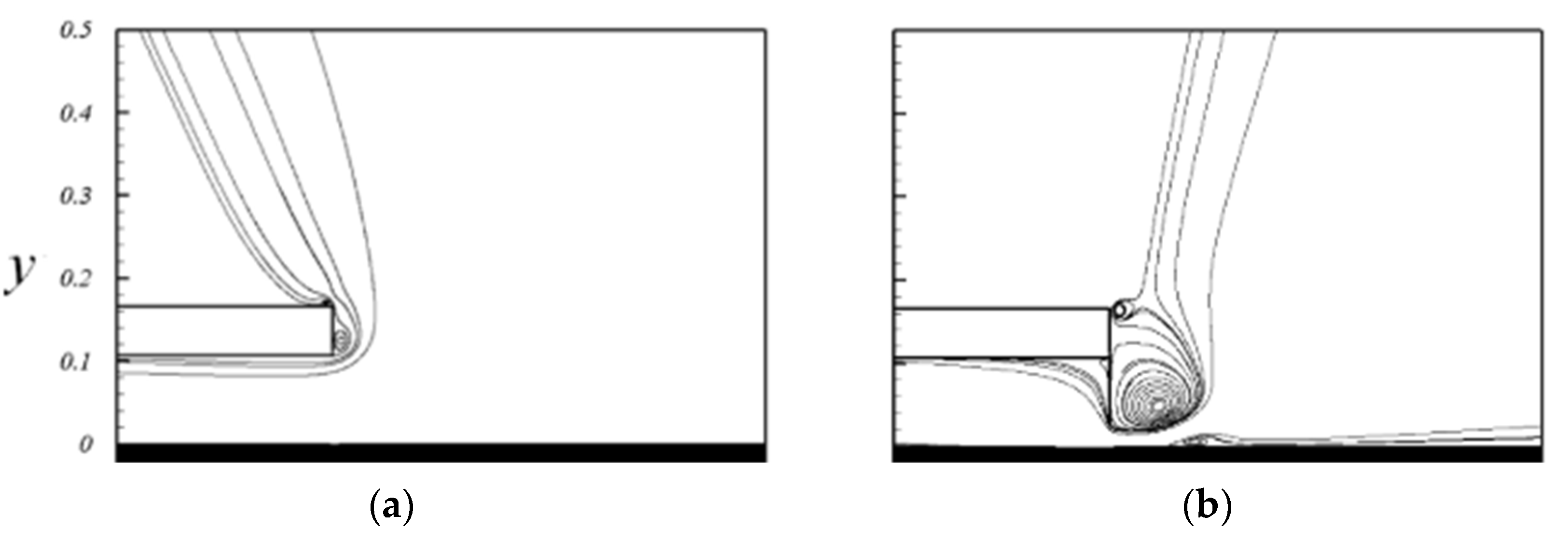
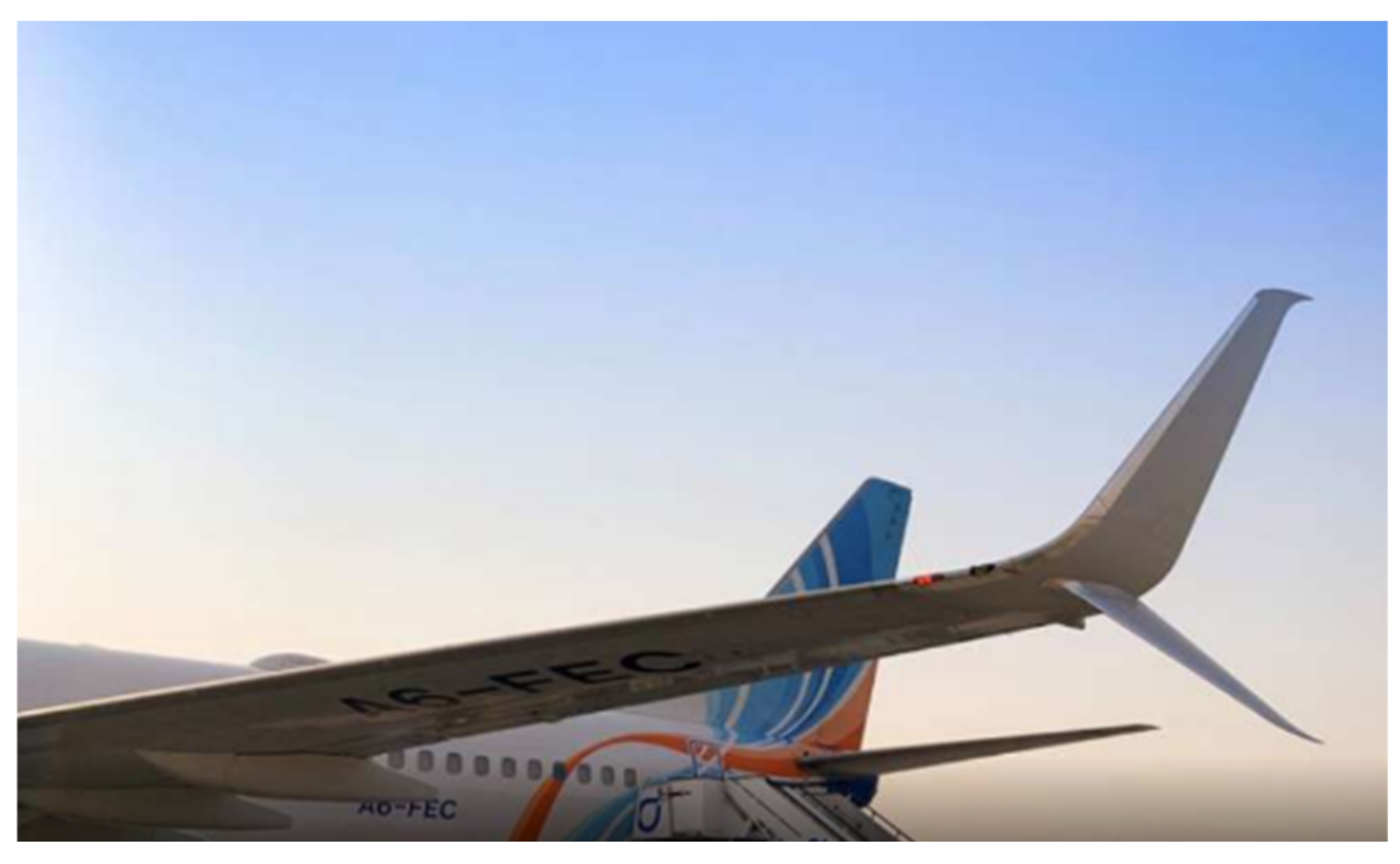
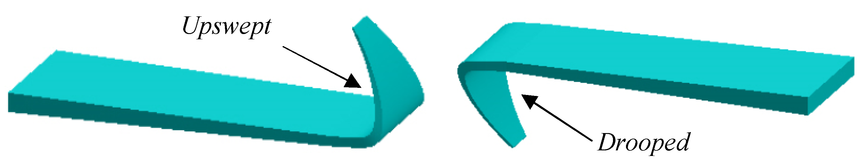
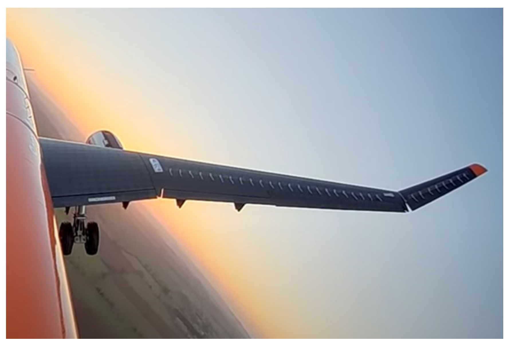
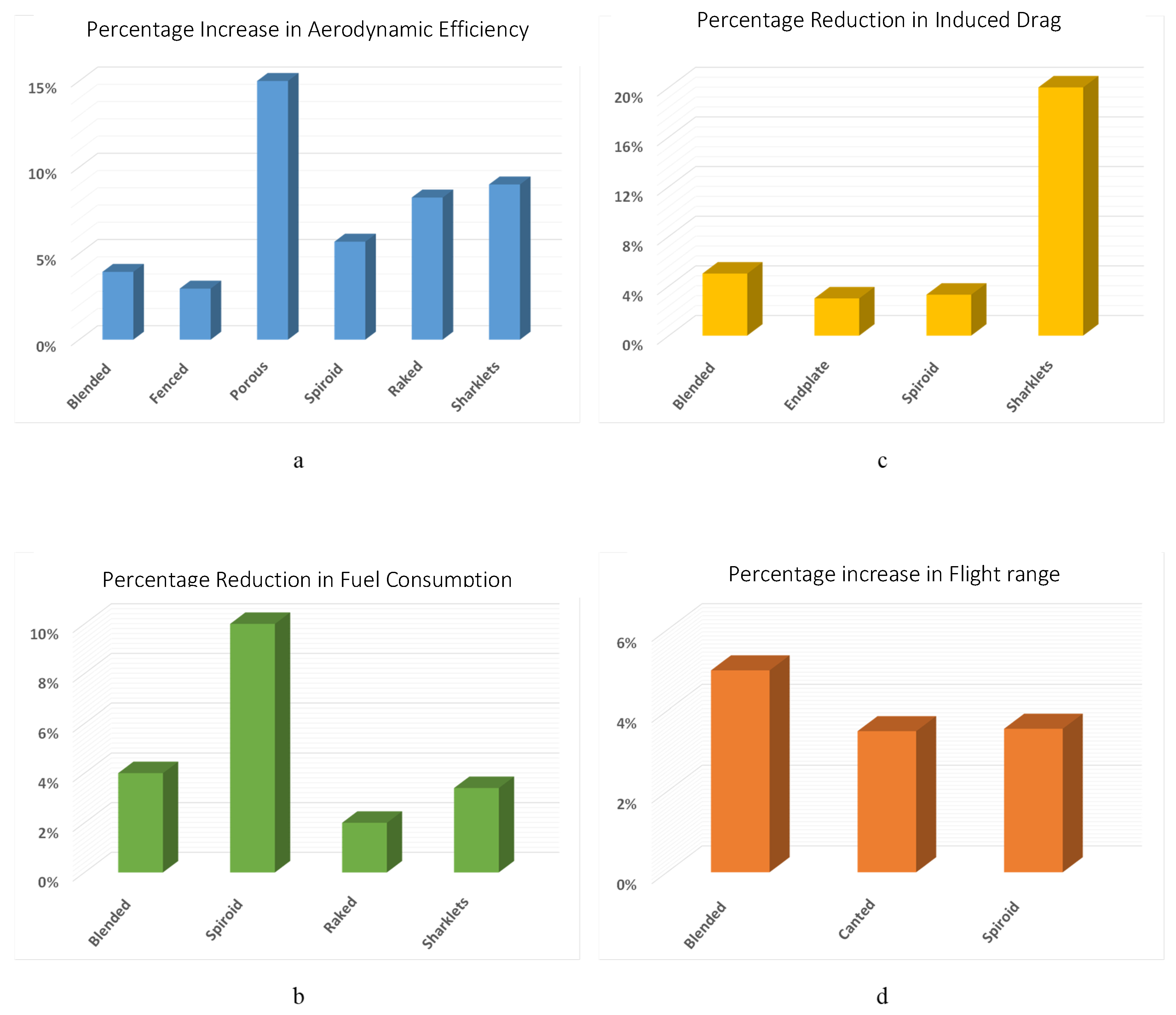
Table 1.
Configurations of the multi-winglets extracted from [110].
Table 1.
Configurations of the multi-winglets extracted from [110].
| Configuration | Winglet Angles in Degree |
|---|---|
| Conf. 11 | A = −30, B = −15, and C = 0 |
| Conf. 19 | A = −30, B = 0, and C = +30 |
| Conf. 40 | A = +45, B = +30, and C = +15 |
| Conf. 44 | A = −15, B = −30, and C = −45 |
| Conf. 47 | A = +60, B = +30, and C = 0 |
| Conf. 48 | A = +45, B = +15, and C = +15 |
Table 2.
Salient features of passive and active wingtips.
| Wingtip Name | Wingtip Type | Salient Features |
|---|---|---|
| Blended | Passive | |
| Fenced | Passive | |
| Endplates | Passive |
|
| Porous wingtip | Passive |
|
| Canted winglet | Passive |
|
| Spiroid | Passive | |
| Raked | Passive |
|
| Sharklets | Passive | |
| Oscillating winglet | Active | |
| Pulsed jet winglet | Active |
|
| Flapping winglet | Active |
|
| Adaptive Multi-winglets | Active |
Disclaimer/Publisher’s Note: The statements, opinions and data contained in all publications are solely those of the individual author(s) and contributor(s) and not of MDPI and/or the editor(s). MDPI and/or the editor(s) disclaim responsibility for any injury to people or property resulting from any ideas, methods, instructions or products referred to in the content. |
© 2023 by the authors. Licensee MDPI, Basel, Switzerland. This article is an open access article distributed under the terms and conditions of the Creative Commons Attribution (CC BY) license (https://creativecommons.org/licenses/by/4.0/).
Share and Cite
MDPI and ACS Style
Gharbia, Y.; Derakhshandeh, J.F.; Alam, M.M.; Amer, A.M. Developments in Wingtip Vorticity Mitigation Techniques: A Comprehensive Review. Aerospace 2024, 11, 36. https://doi.org/10.3390/aerospace11010036
AMA Style
Gharbia Y, Derakhshandeh JF, Alam MM, Amer AM. Developments in Wingtip Vorticity Mitigation Techniques: A Comprehensive Review. Aerospace. 2024; 11(1):36. https://doi.org/10.3390/aerospace11010036
Chicago/Turabian StyleGharbia, Yousef, Javad Farrokhi Derakhshandeh, Md. Mahbub Alam, and A. M. Amer. 2024. "Developments in Wingtip Vorticity Mitigation Techniques: A Comprehensive Review" Aerospace 11, no. 1: 36. https://doi.org/10.3390/aerospace11010036
Note that from the first issue of 2016, this journal uses article numbers instead of page numbers. See further details here.