UNIT-06
High Voltage D.C.
Transmission System
Introduction
Introduction:
HVDC Transmission System I
• Starting in the late 1880s,
Thomas Edison and Nikola Tesla were embroiled in a battle now known as the War of the
Currents.
• Thomas Edison developed direct
current(D.C.)that runs continually in a single
direction (like in a battery or a fuel cell)which was standard in U.S
Direct current is not easily converted
to higher or lower voltages.
• Nikola Tesla believed that
alternating current (or AC) was the solution to this problem. Alternating current reverses
direction a certain number of times per
second (60 cycles/sec in the U.S)and can be converted to different
voltages relatively easily using a
transformer.
• Edison, not wanting to lose the
royalties he was earning from his direct current patents, began a campaign to discredit
alternating current and spreaded
misinformation saying that alternating current was more dangerous.
• General Electric bid to electrify
the fair using Edison’s direct current for
$554,
000, but lost to George Westinghouse, who said he could power the fair for only $399, 000 using Tesla’s
alternating current.
Introduction:
HVDC Transmission System II
• That same year, the Niagara Falls
Power Company decided to award
Westinghouse – who had licensed Tesla’s polyphase AC induction motor
patent
– the contract to generate power
from Niagara Falls.
• On Nov. 16, 1896, Buffalo was lit
up by the alternating current from Niagara
Falls. By this time General Electric had decided to jump on the
alternating current train, too.
• It would appear that alternating
current had all but obliterated direct current,
but in recent years direct current has seen a bit of a renaissance.
• Today our electricity is still
predominantly powered by alternating current, but computers, LEDs, solar cells and electric
vehicles all run on DC power.
• Different methods are now
available for converting direct current to higher and lower voltages.
• Since direct current is more
stable, companies are finding ways of using high voltage direct current (HVDC) to transport
electricity long distances with less
electricity loss.
Introduction:
HVDC Transmission System III
• So it appears the War of the
Currents may not be over yet. But instead of
continuing in a heated AC vs. DC battle,
• It looks like the two currents
will end up working parallel to each other in a
sort of hybrid system.
• None of that would be possible
without the genius of both Tesla and Edison.
Historical
Development:World Wide I
• The most significant contribution
to HVDC came when the Gotland Scheme in
Sweden was commissioned in 1954 to be the World’s first commercial
HVDC transmission system [rating:20MW,
single pole, -100kV, 96km, sea return]
• In the beginning all HVDC schemes
used mercury arc valves, invariably single
phase in construction.
• In 1961 the cross channel link
between England and France was put into
operation. [rating:80MW, two pole, ±100kV, 64km, without sea
return, asynchronous link at 60Hz
frequency].
• The Sakuma Frequency Changer
which was put into operation in 1965 to
interconnects the 50Hz and the 60Hz systems of Japan.[rating:300MW,
two pole, ±250kV, 0km, without
sea return, asynchronous link between 50Hz 60Hz
frequency].
• In 1968 the Vancouver Island HVDC
scheme was operated in parallel with an
a.c.
link. [rating:300MW, single pole, +250kV, 0km]
Historical
Development:World Wide II
• In 1970 a solid state addition
(Thyristors) was made to the Gotland scheme
with a rating of [rating:30MW, two pole, ±150kV, 96km]
• Also in 1970 the Kingsnorth
scheme in England was operated on an
experimental basis. [rating:640MW, two pole, ±260kV, 82km,
underground cables]
• The first converter station using
exclusively Thyristors was the Eel River
scheme in Canada. Commissioned in 1972, [rating:320MW, two pole, ±80kV, 0km, asynchronous link between two ac system
with same frequency 60Hz]
• Now a days many HVDC links are
established with high power rating up
7200MW and voltage level ±800kV in China with highest length
2375km in Brazil.
• Many companies such as General
Electric, Toshiba, Alsthom,ABB, Siemens,
BHEL,Hitachi etc. are in the business of HVDC transmission system.
Historical
Development:India I
Sr.
No.
|
System/Project
|
Year
of
Commissioned
|
Supplier
|
Power
rating
(MW)
|
Voltage
Rating
(kV)
|
Length
(km)
|
1
|
Vindyachal
|
1989
|
ABB
|
500
|
2 × 69.7
|
0
|
2
|
National HVDC Stage-I
|
1989
|
BHEL
|
100
|
100
|
196
|
3
|
Rihand-Delhi
|
1991-92
|
ABB/BHEL
|
750/1500
|
±500
|
814
|
4
|
Chandrapur-
Ramagundam
|
1997-98
|
GED Alsthom
|
100
|
2 × 205
|
0
|
5
|
Chandrapur
Padghe
|
1998
|
ABB/BHEL
|
1500
|
±500
|
736
|
6
|
Vizag-I
|
1999
|
GEC Alsthom
|
500
|
205
|
0
|
7
|
National HVDC Stage-II
|
2000
|
BHEL
|
100
|
200
|
196
|
8
|
Sasaram
|
2002
|
GEC Alsthom
|
500
|
205
|
0
|
9
|
Talcher-Kolar
|
2003
|
Siemens
|
2000
|
±500
|
1400
|
10
|
Vizag-II
|
2005
|
ABB
|
500
|
±88
|
0
|
11
|
Balia-Bhiwadi
|
2009
|
Siemens/BHEL
|
2500
|
±500
|
780
|
12
|
Mundra - Haryana
|
2012
|
Siemens
|
2500
|
±500
|
960
|
13
|
Biswanath-Agra
|
2015
|
ABB
|
600
|
±800
|
1728
|
Comparison AC and DC
Transmission
The
most crucial difference between the AC and the DC transmission line is that the
AC transmission line uses three conductors for power transmission whereas the
DC transmission line requires two conductors. The other differences between the
AC and DC transmission lines are explained below in the comparison chart.
The
transmission line is a closed system through which the power is transfer from
generating station to the consumers. The transmission lined are
categorised into three categories.
·
Short
Transmission Line –
The length of the short transmission line is up to 80Km.
·
Medium
Transmission Line –
The length of the medium transmission line lies between 80km to 200km.
·
Long
transmission Line –
The length of long transmission line is greater than 150km.
The
supports conductor, conductor, insulator, cross arms and clamp, fuses and
isolating switches, phases plates etc. are the main component of the
transmission lines.
Basis for Comparison
|
AC Transmission Line
|
DC Transmission Line
|
Definition
|
The ac transmission line transmit
the alternating current.
|
The dc transmission line is used
for transmitting the direct current.
|
Number of Conductors
|
Three
|
Two
|
Inductance & surges
|
Have
|
Don’t Have
|
Voltage drop
|
High
|
Low
|
Skin Effect
|
Occurs
|
Absent
|
Need of Insulation
|
More
|
Less
|
Interference
|
Have
|
Don’t Have
|
Corona Loss
|
Occur
|
Don’t occur
|
Dielectric Loss
|
Have
|
Don’t have
|
Synchronizing and Stability
Problem
|
No difficulties
|
Difficulties
|
Cost
|
Expensive
|
Cheap
|
Length of conductors
|
Small
|
More
|
Repairing and Maintenance
|
Easy and Inexpensive
|
Difficult and Expensive
|
Transformer
|
Requires
|
Not Requires
|
AC
Transmission Line
The
ac transmission line is used for transmitting the bulk of the power generation
end to the consumer end. The power is generated in the generating station. The
transmission line transmits the power from generation to the consumer end. The
power is transmitted from one end to another with the help of step-up and step
down transformer.
DC Transmission Line
In
DC transmission line, the mercury arc rectifier converts the alternating
current into the DC. The DC transmission line transmits the bulk power over
long distance. At the consumer ends the thyratron converts the DC into the AC.
Key
Differences Between AC and DC Transmission Line
1.
The AC transmission line transmits
the alternating current over a long distance. Whereas, the DC transmission line
is used for transmitting the DC over the long distance.
2.
The AC transmission line uses three
conductors for long power transmission. And the DC transmission line uses two
conductors for power transmission.
3.
The AC transmission line has
inductance and surges whereas the DC transmission line is free from inductance
and surges. The inductance and the surges are nothing but the wave of the high
voltage which occurs for short duration.
4.
The high voltage drop occurs across
the AC terminal lines when their end terminals voltage are equal. The DC
transmission line is free from inductance, and hence no voltage drop occurs
across the line.
5.
The phenomenon of the skin effect
occurs only in the AC transmission line. The skin effect causes the losses, and
this can be reduced by decreasing the cross-section area of the conductor. The
phenomenon of skin effect is completely absent in the DC transmission line.
6.
At same voltage, the DC transmission
line has less stress as compared to the AC transmission line. Hence, DC
requires the less insulation as compared to AC.
7.
The communication line interference
is more in the AC transmission line as compared to the DC transmission line.
8.
The corona effect is the phenomenon
through which the ionization occurs across the conductor. And this ionisation
causes the losses in the conductor. The phenomenon of corona effect occurs only
in the ac transmission line and not in the dc transmission line.
9.
The dielectric loss occurs in the ac
transmission line and not in the DC transmission line.
10. The AC transmission line has the difficulties of
synchronisation and stability whereas the DC transmission line is free from
stability and synchronisation.
11. The AC transmission line is less expensive as compared to
the DC transmission line.
12. The small conductor is used for AC power transmission as
compared to the DC transmission.
13. The AC transmission line requires the transformer for
step-up and step-down the voltage. Whereas in DC transmission line the booster
and chopper are used for step-up and step-down the voltage.
Disadvantages of HVDC
System I
1
Expensive converters: Expensive
Converter Stations are required at each end
of a DC transmission link, whereas only transformer stations are
required in an AC link.
2
Reactive power requirement: Converters
require much reactive power, both in
rectification as well as in inversion. At each converter the reactive
power consumed may be as much at 50% of
the active power rating of the DC link.
The reactive power requirement is partly supplied by the filter
capacitance, and partly by synchronous
or static capacitors that need to be installed for the purpose.
3
Generation of harmonics: Converters
generate a lot of harmonics both on the
DC side and on the AC side. Filters are used on the AC side to reduce the amount of harmonics transferred to the AC
system. On the DC system, smoothing
reactors. are used. These components add to the cost of the converter.
Disadvantages of HVDC
System II
4
Difficulty of circuit breaking: Due
to the absence of a natural current zero
with DC, circuit breaking is difficult. This is not a major problem in
single HVDC link systems, as circuit
breaking can be accomplished by a very rapid
absorbing of the energy back into the AC system. However the lack of
HVDC circuit breakers hampers
multi-terminal operation.
5
Difficulty of voltage transformation: Power
is generally used at low voltage, but
for reasons of efficiency must be transmitted at high voltage. The absence of the equivalent of DC transformers makes it
necessary for voltage transformation to
carried out on the DC side of the system and prevents a purely DC system being used.
6
Absence of overload capacity: Converters
have very little overload capacity
unlike transformers.
Different types of HVDC links
In the previous topic, we learn about the HVDC
transmission, which is economical for long distance power transmission, and
for the interconnection of two or more networks that has different frequencies
or voltages. For connecting two networks or system, various types of HVDC links
are used. HVDC links are classified into three types. These links are explained
below;
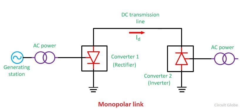
Monopolar link –
It has a single conductor of negative polarity and uses
earth or sea for the return path of current. Sometimes the metallic return is
also used. In the Monopolar link, two converters are placed at the end of each
pole. Earthing of poles is done by earth electrodes placed about 15 to 55 km
away from the respective terminal stations. But this link has several
disadvantages because it uses earth as a return path. The monopolar link is not
much in use nowadays.
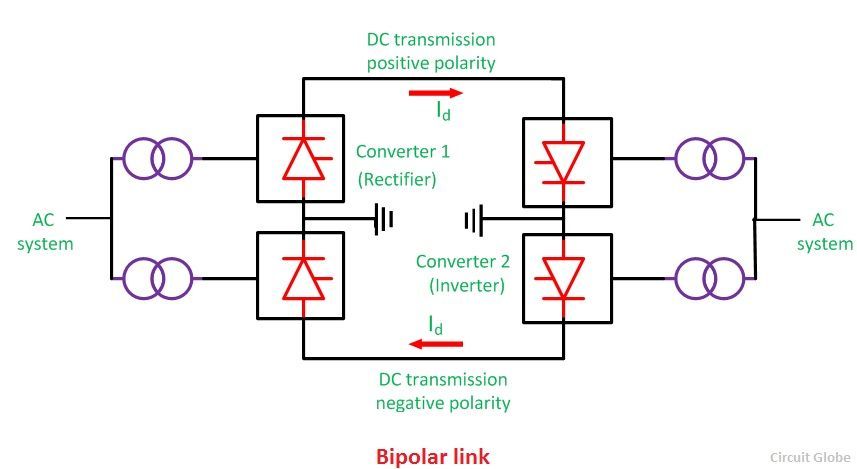
Bipolar link –
The Bipolar link has two
conductors one is positive, and the other one is negative to the earth. The
link has converter station at each end. The midpoints of the converter stations
are earthed through electrodes. The voltage of the earthed electrodes is just
half the voltage of the conductor used for transmission the HVDC.
The most significant advantage of the bipolar link is
that if any of their links stop operating, the link is converted into Monopolar
mode because of the ground return system. The half of the system continues
supplies the power. Such types of links are commonly used in the HVDC systems.
Homopolar link–
It has two conductors of the same polarity usually
negative polarity, and always operates with earth or metallic return. In the
homopolar link, poles are operated in parallel, which reduces the insulation
cost.
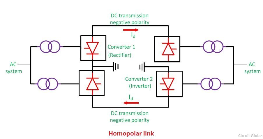
The
homopolar system is not used presently.
HVDC Transmission System
Definition: The system which uses the direct
current for the transmission of the power such type of system is called HVDC (High Voltage Direct Current) system. The HVDC system
is less expensive and has minimum losses. It transmits the power between the
unsynchronized AC system.
Component of an HVDC Transmission System
The HVDC system has the following main components.
·
Converter Station
·
Converter Unit
·
Converter Valves
·
Converter Transformers
·
Filters
o AC filter
o DC filter
o High-frequency filter
·
Reactive Power Source
·
Smoothing Reactor
·
HVDC System Pole
Converter Station
The terminal substations which convert an AC to
DC are called rectifier terminal while the terminal substations which
convert DC to AC are called inverter terminal. Every terminal is designed to
work in both the rectifier and inverter mode. Therefore, each terminal is
called converter terminal, or rectifier terminal. A two-terminal HVDC system
has only two terminals and one HVDC line.
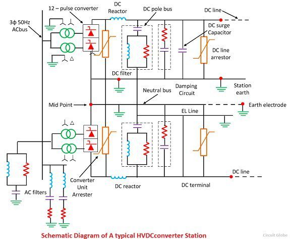
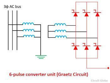
Converter Unit
The conversion from AC to DC and vice versa is done in HVDC
converter stations by using three-phase bridge converters. This bridge circuit
is also called Graetz circuit. In HVDC transmission a 12-pulse bridge converter
is used. The converter obtains by connecting two or 6-pulse bridge in series.
Converter Valves
The modern HVDC converters use 12-pulse converter units. The
total number of a valve in each unit is 12. The valve is made up of series
connected thyristor modules.The number of thyristor valve depends on the
required voltage across the valve. The valves are installed in valve
halls, and they are cooled by air, oil, water or freon.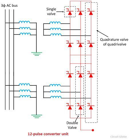
Converter Transformer
The converter transformer converts the AC networks to DC networks or vice versa.
They have two sets of three phase windings. The AC side winding is connected to
the AC bus bar, and the valve side winding is connected to valve bridge.These
windings are connected in star for one transformer and delta to another.
The AC side windings of the two, three phase transformer are
connected in stars with their neutrals grounded. The valve side transformer
winding is designed to withstand alternating voltage stress and direct voltage
stress from valve bridge. There are increases in eddy current losses due to the
harmonics current. The magnetisation in the core of the converter transformer
is because of the following reasons.
· The alternating voltage from AC network containing
fundamentals and several harmonics.
·
The direct voltage from valve side terminal also has some
harmonics.
Filters
The AC and DC harmonics are generated in HVDC converters. The
AC harmonics are injected into the AC system, and the DC harmonics are injected
into DC lines. The harmonics have the following advantages.
1.
It causes the interference in telephone lines.
2.
Due to the harmonics, the power losses in machines and
capacitors are connected in the system.
3.
The harmonics produced resonance in an AC circuit resulting
in over voltages.
4.
Instability of converter controls.
The harmonics are minimised by using the AC, DC and
high-frequency filters. The types of filter are explained below in details.
·
AC Filters – The AC filters are RLC circuit connected between phase and
earth. They offered low impedances to the harmonic frequencies. Thus, the AC
harmonic currents are passed to earth. Both tuned and damped filters are used.
The AC harmonic filter also provided a reactive power required for
satisfactory operation of converters.
·
DC Filters – The DC filter is connected between the pole bus and
neutral bus. It diverts the DC harmonics to earth and prevents them from
entering DC lines. Such a filter does not require reactive power as DC line
does not require DC power.
·
High-Frequency Filters – The HVDC converter may produce electrical noise in
the carrier frequency band from 20 kHz to 490 kHz. They also generate radio
interference noise in the megahertz range frequencies. High-frequency filters
are used to minimise noise and interference with power line carrier
communication. Such filters are placed between the converter transformer and
the station AC bus.
Reactive Power Source
Reactive power is required for the operations of the
converters. The AC harmonic filters provide reactive power partly. The
additional supply may also be obtained from shunt capacitors synchronous phase
modifiers and static var systems. The choice depends on the speed of control
desired.
Smoothing Reactor
Smoothing reactor is an oil filled oil cooled reactor having
a large inductance. It is connected in series with the converter before the DC
filter. It can be located either on the line side or on the neutral side.
Smoothing reactors serve the following purposes.
1.
They smooth the ripples in the direct current.
2.
They decrease the harmonic voltage and current in the DC
lines.
3.
They limit the fault current in the DC line.
4.
Consequent commutation failures in inverters are prevented by
smoothing reactors by reducing the rate of rising of the DC line in the bridge
when the direct voltage of another series connected voltage collapses.
5.
Smoothing reactors reduce the steepness of voltage and
current surges from the DC line. Thus, the stresses on the converter valves and
valve surge diverters are reduced.
HVDC System Pole
The HVDC system pole is the part of an HVDC system
consisting of all the equipment in the HVDC substation. It also interconnects
the transmission lines which during normal operating condition exhibit a common
direct polarity with respect to earth. Thus the word pole refers to the path of
DC which has the same polarity with respect to earth. The total pole includes
substation pole and transmission line pole.
Types of an HVDC System
The different types of an HVDC system are explained below in
details.
Back-to-Back HVDC Station
The
HVDC system which transfers energy between the AC buses at the same location is
called back-to-back system or an HVDC coupling system. In back-to-back HVDC
stations, the converters and rectifiers are installed in the same stations. It
has no DC transmission line.
The
back-to-back system provides an asynchronous interconnection between the two
adjacent independently controlled AC networks without transferring frequency
disturbances. The back-to-back DC link reduces the overall conversion cost,
improve the reliability of the DC system. Such type of system is designed for
bipolar operation.
Two Terminal HVDC System
The terminal with two terminals (converter station) and one
HVDC transmission line is called two terminal DC system point-to-point
system. This system does not have any parallel HVDC line and no intermediate
tappings. The HVDC circuit
breaker is
also not required for two-terminal HVDC system.The normal and abnormal current
is controlled effective converter controller.
Multiterminal DC (MTDC) System
This system has more than two converter station and DC
terminal lines. Some of the converter stations operate as rectifier while
others operate as an inverter. The total power taken from the rectifier station
is equal to the power supplied by the inverter station. There are two type of
MTDC Systems
·
Series MTDC System.
·
Parallel MTDC System.
In series MTDC system the converters are connected in series
while in parallel MTDC system, the converters are connected in parallel. The
parallel MTDC system may be operated without the use of an HVDC circuit
breaker.
Advantages of MTDC systems
The following are the advantages of MTDC systems
1.
The MTDC system is more economical and flexible.
2.
The frequency oscillation in the interconnected AC networks
can be damped quickly.
3.
The heavily load AC networks can be reinforced by using MTDC
systems.
Applications of MTDC systems
The following are the applications of the HVDC systems
1.
It transfers the bulk power from several remote generating
sources to several load centres.
2.
The systems are interconnected between two or more AC
systems by radial MTDC systems.
3.
It reinforces the heavy load urban AC networks by MTDC
systems
Advantages of HVDC transmissions
1. A lesser number of conductors
and insulators are required thereby reducing the cost of the overall system.
2. It requires less phase to phase and
ground to ground clearance.
3. Their towers are less costly and
cheaper.
4. Lesser corona loss is less as
compared to HVAC transmission lines of similar power.
5. Power loss is reduced with DC
because fewer numbers of lines are required for power transmission.
6. The HVDC system uses earth return.
If any fault occurs in one pole, the other pole with ‘earth returns’ behaves
like an independent circuit. This results in a more flexible system.
7. The HVDC has the asynchronous
connection between two AC stations connected through an HVDC link; i.e., the
transmission of power is independent of sending frequencies to receiving end
frequencies. Hence, it interconnects two substations with different
frequencies.
8. Due to the absence of frequency in
the HVDC line, losses like skin effect and proximity effect does not occur in
the system.
9. It does not generate or absorb any
reactive power. So, there is no need for reactive power compensation.
10. The very accurate and lossless power
flows through DC link.
Comments
Post a Comment