US9522073B2 - Orientation markers for endovascular delivery system - Google Patents
Orientation markers for endovascular delivery system Download PDFInfo
- Publication number
- US9522073B2 US9522073B2 US13/761,442 US201313761442A US9522073B2 US 9522073 B2 US9522073 B2 US 9522073B2 US 201313761442 A US201313761442 A US 201313761442A US 9522073 B2 US9522073 B2 US 9522073B2
- Authority
- US
- United States
- Prior art keywords
- dilator
- marker
- length extending
- extension
- extending module
- Prior art date
- Legal status (The legal status is an assumption and is not a legal conclusion. Google has not performed a legal analysis and makes no representation as to the accuracy of the status listed.)
- Active
Links
- 239000003550 marker Substances 0.000 claims abstract description 79
- 210000001367 artery Anatomy 0.000 claims description 13
- 230000000717 retained effect Effects 0.000 claims description 13
- 210000005166 vasculature Anatomy 0.000 claims description 11
- 210000001105 femoral artery Anatomy 0.000 claims description 7
- 210000000115 thoracic cavity Anatomy 0.000 claims description 6
- 230000007246 mechanism Effects 0.000 claims description 5
- 210000000709 aorta Anatomy 0.000 description 10
- 238000000034 method Methods 0.000 description 7
- 239000000463 material Substances 0.000 description 6
- 210000002434 celiac artery Anatomy 0.000 description 5
- 210000002254 renal artery Anatomy 0.000 description 5
- 210000001363 mesenteric artery superior Anatomy 0.000 description 3
- 210000003270 subclavian artery Anatomy 0.000 description 3
- 206010002329 Aneurysm Diseases 0.000 description 2
- 210000002376 aorta thoracic Anatomy 0.000 description 2
- 210000003090 iliac artery Anatomy 0.000 description 2
- 230000014759 maintenance of location Effects 0.000 description 2
- 230000003019 stabilising effect Effects 0.000 description 2
- 241001465754 Metazoa Species 0.000 description 1
- 230000003187 abdominal effect Effects 0.000 description 1
- 210000000702 aorta abdominal Anatomy 0.000 description 1
- 239000000560 biocompatible material Substances 0.000 description 1
- 230000017531 blood circulation Effects 0.000 description 1
- 210000002302 brachial artery Anatomy 0.000 description 1
- 210000001715 carotid artery Anatomy 0.000 description 1
- 239000002872 contrast media Substances 0.000 description 1
- 229940039231 contrast media Drugs 0.000 description 1
- 230000007717 exclusion Effects 0.000 description 1
- 239000007788 liquid Substances 0.000 description 1
- 229920002635 polyurethane Polymers 0.000 description 1
- 239000004814 polyurethane Substances 0.000 description 1
- 125000000391 vinyl group Chemical group [H]C([*])=C([H])[H] 0.000 description 1
- 229920002554 vinyl polymer Polymers 0.000 description 1
- 230000000007 visual effect Effects 0.000 description 1
Images


Classifications
-
- A—HUMAN NECESSITIES
- A61—MEDICAL OR VETERINARY SCIENCE; HYGIENE
- A61F—FILTERS IMPLANTABLE INTO BLOOD VESSELS; PROSTHESES; DEVICES PROVIDING PATENCY TO, OR PREVENTING COLLAPSING OF, TUBULAR STRUCTURES OF THE BODY, e.g. STENTS; ORTHOPAEDIC, NURSING OR CONTRACEPTIVE DEVICES; FOMENTATION; TREATMENT OR PROTECTION OF EYES OR EARS; BANDAGES, DRESSINGS OR ABSORBENT PADS; FIRST-AID KITS
- A61F2/00—Filters implantable into blood vessels; Prostheses, i.e. artificial substitutes or replacements for parts of the body; Appliances for connecting them with the body; Devices providing patency to, or preventing collapsing of, tubular structures of the body, e.g. stents
- A61F2/95—Instruments specially adapted for placement or removal of stents or stent-grafts
-
- A—HUMAN NECESSITIES
- A61—MEDICAL OR VETERINARY SCIENCE; HYGIENE
- A61F—FILTERS IMPLANTABLE INTO BLOOD VESSELS; PROSTHESES; DEVICES PROVIDING PATENCY TO, OR PREVENTING COLLAPSING OF, TUBULAR STRUCTURES OF THE BODY, e.g. STENTS; ORTHOPAEDIC, NURSING OR CONTRACEPTIVE DEVICES; FOMENTATION; TREATMENT OR PROTECTION OF EYES OR EARS; BANDAGES, DRESSINGS OR ABSORBENT PADS; FIRST-AID KITS
- A61F2/00—Filters implantable into blood vessels; Prostheses, i.e. artificial substitutes or replacements for parts of the body; Appliances for connecting them with the body; Devices providing patency to, or preventing collapsing of, tubular structures of the body, e.g. stents
- A61F2/02—Prostheses implantable into the body
- A61F2/04—Hollow or tubular parts of organs, e.g. bladders, tracheae, bronchi or bile ducts
- A61F2/06—Blood vessels
- A61F2/07—Stent-grafts
-
- A—HUMAN NECESSITIES
- A61—MEDICAL OR VETERINARY SCIENCE; HYGIENE
- A61F—FILTERS IMPLANTABLE INTO BLOOD VESSELS; PROSTHESES; DEVICES PROVIDING PATENCY TO, OR PREVENTING COLLAPSING OF, TUBULAR STRUCTURES OF THE BODY, e.g. STENTS; ORTHOPAEDIC, NURSING OR CONTRACEPTIVE DEVICES; FOMENTATION; TREATMENT OR PROTECTION OF EYES OR EARS; BANDAGES, DRESSINGS OR ABSORBENT PADS; FIRST-AID KITS
- A61F2/00—Filters implantable into blood vessels; Prostheses, i.e. artificial substitutes or replacements for parts of the body; Appliances for connecting them with the body; Devices providing patency to, or preventing collapsing of, tubular structures of the body, e.g. stents
- A61F2/95—Instruments specially adapted for placement or removal of stents or stent-grafts
- A61F2/954—Instruments specially adapted for placement or removal of stents or stent-grafts for placing stents or stent-grafts in a bifurcation
-
- A—HUMAN NECESSITIES
- A61—MEDICAL OR VETERINARY SCIENCE; HYGIENE
- A61F—FILTERS IMPLANTABLE INTO BLOOD VESSELS; PROSTHESES; DEVICES PROVIDING PATENCY TO, OR PREVENTING COLLAPSING OF, TUBULAR STRUCTURES OF THE BODY, e.g. STENTS; ORTHOPAEDIC, NURSING OR CONTRACEPTIVE DEVICES; FOMENTATION; TREATMENT OR PROTECTION OF EYES OR EARS; BANDAGES, DRESSINGS OR ABSORBENT PADS; FIRST-AID KITS
- A61F2/00—Filters implantable into blood vessels; Prostheses, i.e. artificial substitutes or replacements for parts of the body; Appliances for connecting them with the body; Devices providing patency to, or preventing collapsing of, tubular structures of the body, e.g. stents
- A61F2/95—Instruments specially adapted for placement or removal of stents or stent-grafts
- A61F2/962—Instruments specially adapted for placement or removal of stents or stent-grafts having an outer sleeve
-
- A—HUMAN NECESSITIES
- A61—MEDICAL OR VETERINARY SCIENCE; HYGIENE
- A61F—FILTERS IMPLANTABLE INTO BLOOD VESSELS; PROSTHESES; DEVICES PROVIDING PATENCY TO, OR PREVENTING COLLAPSING OF, TUBULAR STRUCTURES OF THE BODY, e.g. STENTS; ORTHOPAEDIC, NURSING OR CONTRACEPTIVE DEVICES; FOMENTATION; TREATMENT OR PROTECTION OF EYES OR EARS; BANDAGES, DRESSINGS OR ABSORBENT PADS; FIRST-AID KITS
- A61F2/00—Filters implantable into blood vessels; Prostheses, i.e. artificial substitutes or replacements for parts of the body; Appliances for connecting them with the body; Devices providing patency to, or preventing collapsing of, tubular structures of the body, e.g. stents
- A61F2/02—Prostheses implantable into the body
- A61F2/04—Hollow or tubular parts of organs, e.g. bladders, tracheae, bronchi or bile ducts
- A61F2/06—Blood vessels
- A61F2002/061—Blood vessels provided with means for allowing access to secondary lumens
-
- A—HUMAN NECESSITIES
- A61—MEDICAL OR VETERINARY SCIENCE; HYGIENE
- A61F—FILTERS IMPLANTABLE INTO BLOOD VESSELS; PROSTHESES; DEVICES PROVIDING PATENCY TO, OR PREVENTING COLLAPSING OF, TUBULAR STRUCTURES OF THE BODY, e.g. STENTS; ORTHOPAEDIC, NURSING OR CONTRACEPTIVE DEVICES; FOMENTATION; TREATMENT OR PROTECTION OF EYES OR EARS; BANDAGES, DRESSINGS OR ABSORBENT PADS; FIRST-AID KITS
- A61F2/00—Filters implantable into blood vessels; Prostheses, i.e. artificial substitutes or replacements for parts of the body; Appliances for connecting them with the body; Devices providing patency to, or preventing collapsing of, tubular structures of the body, e.g. stents
- A61F2/95—Instruments specially adapted for placement or removal of stents or stent-grafts
- A61F2002/9505—Instruments specially adapted for placement or removal of stents or stent-grafts having retaining means other than an outer sleeve, e.g. male-female connector between stent and instrument
- A61F2002/9511—Instruments specially adapted for placement or removal of stents or stent-grafts having retaining means other than an outer sleeve, e.g. male-female connector between stent and instrument the retaining means being filaments or wires
-
- A—HUMAN NECESSITIES
- A61—MEDICAL OR VETERINARY SCIENCE; HYGIENE
- A61F—FILTERS IMPLANTABLE INTO BLOOD VESSELS; PROSTHESES; DEVICES PROVIDING PATENCY TO, OR PREVENTING COLLAPSING OF, TUBULAR STRUCTURES OF THE BODY, e.g. STENTS; ORTHOPAEDIC, NURSING OR CONTRACEPTIVE DEVICES; FOMENTATION; TREATMENT OR PROTECTION OF EYES OR EARS; BANDAGES, DRESSINGS OR ABSORBENT PADS; FIRST-AID KITS
- A61F2250/00—Special features of prostheses classified in groups A61F2/00 - A61F2/26 or A61F2/82 or A61F9/00 or A61F11/00 or subgroups thereof
- A61F2250/0058—Additional features; Implant or prostheses properties not otherwise provided for
- A61F2250/0096—Markers and sensors for detecting a position or changes of a position of an implant, e.g. RF sensors, ultrasound markers
- A61F2250/0097—Visible markings, e.g. indicia
Definitions
- This invention relates to a medical device and more particularly to a medical device for the facilitation endovascular delivery of medical devices.
- This invention will be discussed in particular in relation to the delivery and cannulation of thoracoabdominal stent grafts but the invention is not so limited.
- Thoracoabdominal aneurysms are particularly difficult to treat due to the inclusion of four branch vessels (celiac artery, superior mesenteric artery, and renal arteries). Endovascular devices are available which include four branches, but cannulation of each branch independently can be difficult and time consuming, exposing the patient to large amount of contrast and x-rays.
- branch vessels celiac artery, superior mesenteric artery, and renal arteries.
- Endovascular devices are available which include four branches, but cannulation of each branch independently can be difficult and time consuming, exposing the patient to large amount of contrast and x-rays.
- Preloaded wires associated with a fenestrated stent graft and a delivery device have been demonstrated to greatly ease the process of cannulating the branches of the device.
- a fenestrated or side arm stent graft with four preloaded wires with catheters or sheaths are required for the four side branches or fenestrations.
- a preloaded delivery system including four lumens for four catheters or preloaded sheaths in the delivery device would be unacceptably large (28 Fr)
- an alternative option is to individually cannulate the branches using preloaded guide wires from a brachial access site. To accomplish this, the preloaded wires must be inserted from the femoral access with a main delivery device and tracked through the abdominal and thoracic aorta, and out through the brachial artery.
- PCT Patent Application Number PCT/US2011/029037 (published as WO 2011/116308) entitled “INTRODUCER WITH EXTENSION” lodged on 18 Mar. 2011 discloses devices and arrangements for delivery of fenestrated or branched stent grafts using delivery devices incorporating preloaded guide wires and the teaching therein is incorporated herein in its entirety.
- an endovascular delivery device incorporating indwelling guide wires requires that there be some way of ensuring that a manufacturer places the correct indwelling wire into the correct side arm and then that a physician using the device will know which indwelling guide wire passes through which side arm.
- a delivery device is often rotated to encourage it to pass trough the vasculature and it may in fact remain partially twisted.
- Some method is needed to ensure that a physician knows the actual orientation of the endovascular device so that the physician knows which indwelling wire is which when most of the device is hidden within the human or animal body.
- distal with respect to a portion of the aorta, a deployment device or a prosthesis means the end of the aorta, deployment device or prosthesis further away in the direction of blood flow away from the heart and the term proximal means the portion of the aorta, deployment device or end of the prosthesis nearer to the heart.
- proximal means the portion of the aorta, deployment device or end of the prosthesis nearer to the heart.
- the invention comprises an endovascular stent graft delivery device comprising an elongate body and a length extending module, the elongate body comprising a distal portion to remain outside a patient in use and a proximal portion to be introduced into the body to carry a stent graft to a placement site, the proximal portion comprising a nose cone dilator at the proximal end thereof and the length extending module being releasably fastened to the nose cone dilator and extending proximally of the nose cone dilator, the length extending module comprising a distal end which is releasably fastened to the nose cone dilator and a proximal end which in use extends out of the patient, the nose cone dilator comprising a dilator marker and the length extending module comprising a first marker and a second marker, the first marker being at the distal end of the length extending module and the second marker being at the proxi
- the dilator marker comprises an aperture in the nose cone dilator and the first marker and the second marker each comprise a recess in the length extending module.
- Other forms of visual marking such as colour patches are also within the scope of the invention.
- the length extending module is releasably joined to the nose cone dilator with the dilator marker aligned circumferentially with the first marker.
- the first marker, the second marker and the dilator marker are all placed so that in use they are all at a 12 o'clock position with respect to vasculature of a patient, the 12 o'clock position being defined by the anterior position of the vasculature.
- the endovascular stent graft delivery device comprises a plurality of indwelling guide wires extending from the distal portion of the elongate body, through the stent graft to the dilator and through the length extending module, whereby the endovascular stent graft delivery device can be introduced into a patient via a femoral artery and the length extending module can extend out an artery of the thoracic arch whereby to extend the indwelling guide wires out of the artery of the thoracic arch.
- the length extending module comprises an elongate extension sheath and an extension dilator in the extension sheath and the extension dilator extending distally and proximally of the extension sheath, the extension dilator comprising a plurality of longitudinal grooves on an outside surface thereof and the plurality of indwelling guide wires extending along respective longitudinal grooves.
- a stent graft is carried on the proximal portion of the elongate body, the stent graft comprising a tubular body, the tubular body comprising proximal and distal open ends and a plurality of fenestrations or side arms, each of the indwelling guide wires extending through a respective fenestration or side arm, the indwelling guide wires extending through the tubular body proximally of the respective fenestration or side arm and outside the tubular body distally of the respective fenestration or side arm.
- the nose cone dilator at the proximal end of the elongate body comprises a plurality of longitudinal grooves on an outside surface thereof to receive respective indwelling guide wires therealong.
- the plurality of longitudinal grooves on at least part of the outside surface of the dilator comprise a substantially closed tube except for a narrow elongated opening whereby the respective indwelling guide wires are received and retained therein.
- the dilator comprises a proximal aperture and the length extending module is removably engaged into the proximal aperture.
- the length extending module is removably engaged with the dilator by a trigger wire release mechanism, whereby upon release of the trigger wire release mechanism the length extending module can be removed from the dilator.
- the plurality of indwelling guide wires comprise a first and a second continuous indwelling guide wire, each continuous wire extending from the distal portion of the elongate body to the proximal end of the length extending module and returning to the distal portion of the elongate body.
- the length extending module comprises a pair of cross apertures extending into the extension dilator between adjacent longitudinal grooves at the proximal end of the extension dilator whereby each of the first and second indwelling guide wires pass through a respective cross aperture to return in an adjacent longitudinal groove.
- the invention comprises a length extending module for an endovascular delivery device, the length extending module being able to be releasably fastened to a dilator of the endovascular delivery device and arranged to extend proximally of the dilator in use, the length extending module comprising a distal end which is able to be releasably fastened to the dilator and a proximal end which is use extends out of a patient, the length extending module comprising a first marker and a second marker, the first marker being at the distal end of the length extending module and the second marker being at the proximal end of the length extending module, the first marker and the second marker being at the same relative circumferential position whereby the orientation or rotational position of the endovascular delivery device within the patient can be determined by the observation of the position of the second marker.
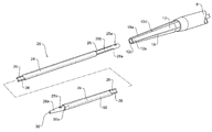
- FIG. 1 shows a stent graft delivery advice according to one embodiment of the present invention
- FIG. 2 shows detail of a portion of the delivery device shown in FIG. 1 in a part assembled condition
- FIG. 3 shows detail of a portion of the delivery device shown in FIG. 1 in an assembled condition
- FIG. 4 shows a longitudinal cross section in detail of a portion of the delivery device shown in FIG. 1 in an assembled condition
- FIG. 5A to 5E show a transverse cross sectional views of portions of the stent graft delivery device according to the present invention
- FIG. 6 shows a stage in the deployment of a stent graft using a delivery device according to the present invention.
- FIG. 7 shows a stent graft with pre-loaded guide wires suitable for the present invention.
- FIG. 1 a stent graft deployment device of one embodiment of the present invention is shown.
- FIG. 1 shows the stent graft delivery device in a condition for introduction into a patient.
- the delivery device 1 comprises a handle portion 2 and an introduction portion 3 .
- the handle portion is intended to remain outside a patient in use and the introduction portion is intended to be introduced into a patient via a puncture into an artery such as the femoral artery.
- a pusher catheter 6 extends proximally from a trigger wire release region 5 of the handle 2 .
- a sheath 8 and sheath hub 10 extends over the pusher catheter 6 .
- the sheath 8 extends proximally to a nose cone dilator 12 . The sheath can be retracted to expose a stent graft retained below it.
- the stent graft is retained on the delivery device in the region distally of the nose cone dilator 12 indicated by the reference numeral 7 .
- a guide wire cannula 14 extends from a Luer lock hub 16 at the distal end of the device through the handle and pusher catheter to extend to and through the nose cone dilator 12 .
- the Luer lock hub 16 is used to introduce liquids such as contrast media to enable tracking of the progress of an operation.
- the nose cone dilator 12 has a plurality of longitudinal grooves 18 on its outside longitudinal surface.
- the grooves are shown in detail in FIGS. 2, 3 and 4 .
- In these grooves 18 lie indwelling guide wires 50 as will be discussed below in more detail.
- a length extending module 20 is releasably mounted to the proximal end 12 a of the nose cone dilator 12 as discussed in more detail below.
- the stent graft is retained in a compressed condition under the sheath 8 just distal of the node cone dilator by releasable trigger wires (not shown) and when the sheath is withdrawn the stent graft expands.
- the proximal end of the stent 40 continues to be retained to the introducer device at a point just distal of the nose cone dilator 12 until it is ultimately released by removal of the releasable trigger wires.
- U.S. Pat. No. 7,803,177 entitled Trigger Wire System issued Sep. 28, 2010 shows trigger wire systems suitable for retaining stent grafts onto delivery devices and the teachings therein a incorporated herein in their entirety.
- FIGS. 2 and 3 show detail of a proximal portion of the delivery device incorporating the length extending module of the present invention shown in FIG. 1 in a part assembled and an assembled condition, respectively.
- the indwelling guide wires are omitted in FIG. 2 to assist with clarity although normally they would be present at this stage of assembly.
- the length extending module 20 comprises a flexible extension dilator 26 surrounded by a flexible sheath 24 .
- the extension dilator 26 extends proximally of the sheath to a dilator tip 26 a and distally of the sheath at a dilator distal end 26 b.
- the extension dilator 26 of the length extending module 20 has a plurality of longitudinal groves 28 on its outside surface. Into these grooves 28 lie the indwelling guide wires 50 as shown in FIG. 3 . The indwelling guide wires 50 are retained in the grooves 28 by the sheath 24 .
- the dilator 26 also has a guide wire lumen 30 .
- the longitudinal grooves 28 terminate at 28 a before the distal end 26 b of the dilator 26 and also terminate before the dilator tip 26 a at the proximal end of the extension dilator.
- FIG. 5A shows a cross section along the line 5 A- 5 A′ on the tapered region nose cone dilator 12 of FIG. 3 .
- the tapered region of the nose cone dilator 12 has four longitudinal grooves 18 arranged orthogonally on its outer surface. Into each of these grooves is received an indwelling guide wire 50 . A detail of such a groove is shown in FIG. 5C .
- Also shown in FIG. 5A is the trigger wire 29 .
- the groove 18 a is wider than the other grooves 18 so that the trigger wire 29 and the indwelling guide wire 50 can both be received into the groove. This ensures, particularly in the region of the nose cone dilator which is engaged by the sheath 8 (see FIG. 3 ) that the overall diameter of the device is not increased.
- the grooves 18 in the nose come dilator may be as shown in FIG. 5D .
- the grooves 18 are a substantially closed tube except for a narrow elongated opening 18 a whereby the respective indwelling guide wires are received and retained therein.
- the substantially closed portion of the grooves 18 is on the tapered portion of the nose cone dilator. With the indwelling guide wires retained in the substantially closed groove there is less chance of the wire coming out of the groove during deployment and possible causing trouble entangling with other portions of the delivery device.
- the nose cone dilator is formed from a polyurethane vinyl material which exhibits a degree of elasticity or flexibility so that when it is desired to remove the indwelling guide wire the sides of the opening can be deflected to allow removal.
- a sheath and dilator are fed down over the indwelling guide wire from the proximal end and the dilator acts to draw the indwelling guide wire out of the substantially closed groove.
- FIG. 5B shows a transverse cross section of the length extending module.
- a central aperture 30 is for traversing the length extending module over a guide wire as discussed below.
- FIG. 5E shows a transverse cross sectional view of a proximal end of the length extending module 20 .
- the extension dilator 26 has four longitudinal grooves 28 into each of which is received an indwelling guide wire 50 .
- two cross apertures 33 are cut into the extension dilator to join two pairs of adjacent longitudinal apertures 28 so that the indwelling wire 50 can cross over at 50 a to extend back down the adjacent longitudinal groove 28 .
- the indwelling guide wires are used for pre-catheterisation of side arms of the stent graft.
- the dilator distal end 26 b has a first marker 25 a and the dilator tip 26 a has a second marker 25 b . Both of the markers 25 a and 25 b are at the same relative circumferential position on the length extending module 20 . Hence, knowing where the marker is at one end of the length extending module enables a physician, in use, to know where the other end is. This can be useful because during a medical procedure the delivery device is twisted and rotated to encourage it to pass through the vasculature of a patient and at times is passed through some convoluted vasculature and there may be part twists remaining in the delivery device so that it is not immediately apparent which indwelling guide wire is which.
- the length extending module 20 is releasably mounted to the proximal end 12 a of the nose cone dilator 12 by the dilator distal end 26 b being received into a forwardly facing dilator recess 12 c in the nose cone dilator.
- the nose cone dilator 12 has a side aperture 12 d which extends into the forwardly facing dilator recess 12 c within the dilator.
- the aperture 12 d receives a trigger wire as is explained below with reference to FIG. 4 for selective retention and release of the length extending module from the delivery device.
- the aperture 12 d is placed on the nose cone dilator 12 at a selected circumferential position and is the dilator marker.
- FIG. 2 shows the length extending module 20 in an unassembled position but with the first marker 25 a on the dilator 26 aligned with the dilator marker, the aperture 12 d on the dilator 12 .
- FIG. 3 shows the dilator distal end 26 b inserted into the forwardly facing dilator recess 12 c in the dilator.
- each of the indwelling guide wires can be defined as a clock position from the 12 o'clock position.
- FIG. 4 shows in longitudinal cross sectional view the connection arrangement between the nose cone dilator 12 and the length extending module 20 .
- the length extending module 20 comprises the outer sheath 24 and the extension dilator 26 .
- the extension dilator has a plurality of longitudinal groves 28 on its outside surface. The grooves are generally placed at the 12 o'clock, 3 o'clock, 6 o'clock and 9 o'clock positions. Into these grooves 28 lie the indwelling guide wires 50 .
- the indwelling guide wires 50 are retained in the grooves by the sheath 24 . As discussed above the indwelling guide wire crosses over between adjacent longitudinal grooves at 50 a .
- the elongate extension piece 20 also has a guide wire lumen 30 .
- the longitudinal grooves 28 terminate at 28 a before the distal end 26 b of the dilator 26 .
- the distal end 26 b of the extension dilator 26 fits into the proximal recess 12 c in the nose cone dilator 12 .
- an aperture 12 d extends through the nose cone dilator 12 and opens into proximal recess 12 c in the nose cone dilator 12 .
- a trigger wire 29 which extends from the handle of the delivery device enters the hole 12 d and then extends into the longitudinal groove 28 just proximal of the end 28 a of the groove 28 .
- the distal end 26 b of the extension dilator 26 fits into and is retained in proximal recess 12 b in the nose cone dilator 12 by a combination of factors.
- the terminating recesses 28 a means that if the dilator 26 is pulled the trigger wire 29 in the grooves 28 interferes and prevents the removal.
- the indwelling guide wires can be locked at the handle portion and with the bend at 50 a the length extending module cannot move forward and thereby holds the distal end 26 b of the dilator 26 in the recess 12 c.
- FIG. 6 shows a schematic view of the vasculature of a human body.
- the vasculature shown comprises an aorta 60 extending from a heart 62 over a thoracic arch 64 to an aortic bifurcation 66 .
- iliac arteries 68 a and 68 b extend down to respective femoral arteries 70 a and 70 b .
- the brachiocephalic artery 72 From the thoracic arch the brachiocephalic artery 72 , the carotid artery 74 and the left subclavian artery 76 extend.
- aorta there are renal arteries 77 and 78 extending from the aorta and little above them the superior mesenteric artery 79 and celiac artery 80 . These four arteries can generally be referred to as the pararenal arteries.
- the aorta 60 is depicted with an aneurism 82 which has occurred in the region of the pararenal arteries and it is desired to deploy a stent graft into the aorta to span the aneurism while at the same time allowing catheterisation and side arm deployment into the renal arteries, the superior mesenteric artery and the celiac artery.
- a guide wire is introduced through a femoral puncture 91 into the femoral artery 70 a and extended up through the femoral artery 70 a , the iliac artery 68 b and into the aorta 60 until it is just proximal of the pararenal arteries.
- a 12 French sheath 92 with sheath hub 94 is introduced via a brachial puncture in the left subclavian artery 76 and the sheath 92 extended down through the left subclavian artery into the descending aorta 60 a .
- a grasper device with a snare is introduced through the sheath hub 94 and down the sheath 92 until the snare can engage the guide wire.
- the snare is used to draw the guide wire back through the sheath 92 so that it extends out of the hub 94 .
- a catheter, with or without a dilator, is then introduced through the hub 94 and tracked over the through and through guide wire 90 until it exits the femoral puncture 91 .
- the dilator is then removed leaving the catheter in place.
- the proximal end of the extension dilator 26 of the deployment device 1 is introduced into the femoral artery 70 b over the guide wire and engaged with the catheter. This assembly is then deployed through the femoral puncture 91 .
- the catheter and the elongate extension 20 of the introduction device 1 track over the guide wire. This is continued until the catheter is completely withdrawn and the extension catheter 24 and extension dilator extend into the sheath 92 and out through the hub 94 . At this stage as is shown in FIG.
- the nose cone dilator 12 of the introduction device is in such a position in the aorta 60 that the stent graft retained within the sheath 8 is in proximity to its desired final position and the length extending module extends out of the shoulder of the patient.
- indwelling guide wires 50 are released from the handle portion of the delivery device 1 so that indwelling guide wires 50 can be separated from the elongate extension piece 20 and cut to give four separate indwelling guide wires.
- the elongate extension piece 20 can then be removed from its selective engagement with the proximal end 12 a of the nose cone dilator 12 .
- the indwelling guide wires 50 are then essentially through-and-through guide wires along with the main guide wire 90 but the indwelling guide wires are acting as pre-catheterised guide wires for the various side arms of the stent graft.
- the guide wires 50 can be recognised to relate a guide wire to a particular side arm of the stent graft by it position in the grooves of the length extending module relative to the second marker 25 b (see FIG. 2 ) as discussed above.
- sheath hub 10 is retracted to withdraw the sheath 8 from the stent graft so that the stent graft is at least partially exposed but the proximal end is still retained by means not shown just distal of the nose cone dilator 12 .
- a 7 French vessel access sheath and dilator can then be advanced over one of the indwelling guide wires 50 into the hub 94 and through the sheath 92 to exit from the distal end of the sheath 92 and to extend into the interior of the stent graft and out through the distal opening of one of the low profile side arms 46 a (see FIG. 7 ).
- the Indwelling guide wire 50 still extends through the material of the stent graft distal of the low profile side arm.
- the dilator of the vessel access sheath can then be retracted from the brachial end of the arrangement and a further guide wire introduced to catheterise the celiac artery 80 (for instance).
- the indwelling guide wire 50 which still extends through the material of the stent graft distal of the low profile side arm assists in stabilising the vessel access sheath where it extends from the low profile side arm.
- Standard catheter and wire techniques can then be used to manipulate the catheter and stiff wire into the selected target vessel to deploy side arms and/or covered bridging stents into each of the pararenal vessels.
- the respective indwelling guide wire 50 can be removed.
- the sheath 8 can then be retracted to release the distal end of the stent graft and the proximal retention mechanisms can be activated to release the proximal end to fully deploy the stent graft.
- the introduction device 1 can then be retracted through the femoral puncture 91 and the access sheath 92 retracted through the brachial puncture 93 .
- FIG. 7 shows a stent graft suitable for use with the present invention.
- the stent graft as shown in FIG. 7 has a tubular body of a biocompatible graft material which is supported by self expanding zig zag stents.
- the stent graft has a number of low profile side arms each of which open outside the stent graft facing distally. These side arms are for receiving side arm extensions to extend to the side branch arteries in the region of the renal arteries.
- the side branch arteries in the region of the renal arteries are the left and right arteries and the superior mesenteric and the celiac arteries.
- the stent graft 40 has a tubular body 42 of a biocompatible graft material which is supported by self expanding zig zag stents 44 .
- the stent graft 40 has a number of low profile side arms 46 a , 46 b , 46 c and 46 d each of which open outside the stent graft facing distally.
- Four indwelling guide wires 50 extend through the stent graft from a proximal end 47 and out through the low profile side arms 46 a , 46 b , 46 c and 46 d respectively and extend outside of the stent graft distally of the respective low profile side arms 46 a , 46 b , 46 c and 46 d .
- the indwelling guide wires 50 extend into the interior of the stent graft through the biocompatible material wall at 45 and continue on distally. Passing the indwelling guide wires 50 back into the material of the stent graft distally of the respective low profile side arms assists in stabilising the guide wire and side arm and assists catheterisation of the branch vessels from the side arms. As can be seen in FIG. 1 the indwelling guide wires 50 extend into the lumen 49 of the pusher catheter 6 and exit at the distal end of the handle 5 .
Abstract
Description
Claims (20)
Applications Claiming Priority (2)
| Application Number | Priority Date | Filing Date | Title |
|---|---|---|---|
| AU2012200735 | 2012-02-08 | ||
| AU2012200735A AU2012200735C1 (en) | 2012-02-08 | 2012-02-08 | Orientation markers for endovascular delivery system |
Publications (2)
| Publication Number | Publication Date |
|---|---|
| US20130204342A1 US20130204342A1 (en) | 2013-08-08 |
| US9522073B2 true US9522073B2 (en) | 2016-12-20 |
Family
ID=46683070
Family Applications (1)
| Application Number | Title | Priority Date | Filing Date |
|---|---|---|---|
| US13/761,442 Active US9522073B2 (en) | 2012-02-08 | 2013-02-07 | Orientation markers for endovascular delivery system |
Country Status (3)
| Country | Link |
|---|---|
| US (1) | US9522073B2 (en) |
| EP (1) | EP2626045B1 (en) |
| AU (1) | AU2012200735C1 (en) |
Families Citing this family (7)
| Publication number | Priority date | Publication date | Assignee | Title |
|---|---|---|---|---|
| US9439793B2 (en) | 2013-03-12 | 2016-09-13 | Cook Medical Technologies Llc | Extension for iliac branch delivery device and methods of using the same |
| US10130501B2 (en) | 2013-03-12 | 2018-11-20 | Cook Medical Technologies Llc | Delivery device with an extension sheath and methods of using the same |
| USD753289S1 (en) | 2014-03-03 | 2016-04-05 | The Spectranetics Corporation | Sheath |
| USD753290S1 (en) | 2014-03-03 | 2016-04-05 | The Spectranetics Corporation | Sheath set |
| US9675371B2 (en) | 2014-03-03 | 2017-06-13 | The Spectranetics Corporation | Dilator sheath set |
| US10231858B2 (en) | 2014-12-22 | 2019-03-19 | Cook Medical Technologies Llc | Delivery system for preloaded fenestrated device |
| US11096810B2 (en) | 2017-11-29 | 2021-08-24 | Cook Medical Technologies Llc | Preloaded pusher tip for endografts |
Citations (30)
| Publication number | Priority date | Publication date | Assignee | Title |
|---|---|---|---|---|
| US5383852A (en) | 1992-12-04 | 1995-01-24 | C. R. Bard, Inc. | Catheter with independent proximal and distal control |
| US5429617A (en) | 1993-12-13 | 1995-07-04 | The Spectranetics Corporation | Radiopaque tip marker for alignment of a catheter within a body |
| US5746766A (en) | 1995-05-09 | 1998-05-05 | Edoga; John K. | Surgical stent |
| US5921978A (en) | 1997-06-20 | 1999-07-13 | Ep Technologies, Inc. | Catheter tip steering plane marker |
| US6285903B1 (en) | 1998-06-30 | 2001-09-04 | Eclipse Surgical Technologies, Inc. | Intracorporeal device with radiopaque marker |
| US6520934B1 (en) | 1999-12-29 | 2003-02-18 | Advanced Cardiovascular Systems, Inc. | Catheter assemblies with flexible radiopaque marker |
| US20040006381A1 (en) | 2000-05-30 | 2004-01-08 | Jacques Sequin | Noncylindrical drug eluting stent for treating vascular bifurcations |
| US6695875B2 (en) | 2000-03-14 | 2004-02-24 | Cook Incorporated | Endovascular stent graft |
| US6827726B2 (en) | 2001-01-19 | 2004-12-07 | Boston Scientific Corporation | Introducer for deployment of branched prosthesis |
| US6849087B1 (en) | 1999-10-06 | 2005-02-01 | Timothy A. M. Chuter | Device and method for staged implantation of a graft for vascular repair |
| US20050059890A1 (en) * | 2003-07-31 | 2005-03-17 | Wislon-Cook Medical Inc. | System and method for introducing multiple medical devices |
| US20050113686A1 (en) | 2003-11-21 | 2005-05-26 | Peckham John E. | Rotational markers |
| US20050159773A1 (en) | 2004-01-20 | 2005-07-21 | Scimed Life Systems, Inc. | Expandable retrieval device with dilator tip |
| US20050255317A1 (en) | 2003-09-22 | 2005-11-17 | Advanced Cardiovascular Systems, Inc. | Polymeric marker with high radiopacity for use in medical devices |
| US7108715B2 (en) | 2001-10-26 | 2006-09-19 | Cook Incorporated | Endoluminal graft |
| US20060241465A1 (en) | 2005-01-11 | 2006-10-26 | Volcano Corporation | Vascular image co-registration |
| US20070083215A1 (en) | 2005-10-07 | 2007-04-12 | Hamer Rochelle M | Conduit for interventional procedures |
| US20070123910A1 (en) | 2005-11-16 | 2007-05-31 | William A. Cook Australia Pty Ltd. | Stent graft introducer |
| US20070250154A1 (en) | 2006-04-19 | 2007-10-25 | William A. Cook Australia Pty Ltd. | Twin bifurcated stent graft |
| US20080221656A1 (en) * | 2007-03-06 | 2008-09-11 | William A. Cook Australia Pty. Ltd. | Endovascular deployment device |
| US7815608B2 (en) | 2007-04-02 | 2010-10-19 | William Cook Australia Pty. Ltd. | High flex introducer assembly |
| WO2010127040A1 (en) | 2009-04-28 | 2010-11-04 | Endologix, Inc. | Apparatus and method of placement of a graft or graft system |
| US7867270B2 (en) | 2006-06-02 | 2011-01-11 | William A. Cook Australia Pty. Ltd. | Multi-port delivery device |
| US7998186B2 (en) | 2003-10-14 | 2011-08-16 | William A. Cook Australia Pty. Ltd. | Introducer for a side branch device |
| US8012193B2 (en) | 2003-10-14 | 2011-09-06 | William A. Cook Australia Pty, Ltd | Introducer for an iliac side branch device |
| WO2011116308A1 (en) | 2010-03-19 | 2011-09-22 | Cook Medical Technologies Llc | Introducer with extension |
| US8043354B2 (en) | 2004-06-16 | 2011-10-25 | William A. Cook Australia Pty. Ltd. | Thoracic deployment device and stent graft |
| US20110295111A1 (en) | 2009-02-12 | 2011-12-01 | Koninklijke Philips Electronics N.V. | System for determining the orientation of a catheter |
| US8118854B2 (en) | 2006-09-28 | 2012-02-21 | Cook Medical Technologies Llc | Endovascular delivery device |
| US20120172968A1 (en) | 2006-04-27 | 2012-07-05 | William A. Cook Australila Pty. Ltd. | Controlled sequential deployment |
Family Cites Families (2)
| Publication number | Priority date | Publication date | Assignee | Title |
|---|---|---|---|---|
| US5683451A (en) * | 1994-06-08 | 1997-11-04 | Cardiovascular Concepts, Inc. | Apparatus and methods for deployment release of intraluminal prostheses |
| CA2486390C (en) | 2002-05-29 | 2011-01-04 | William A. Cook Australia Pty. Ltd. | Trigger wire system for a prosthesis deployment device |
-
2012
- 2012-02-08 AU AU2012200735A patent/AU2012200735C1/en active Active
-
2013
- 2013-02-06 EP EP13154272.2A patent/EP2626045B1/en active Active
- 2013-02-07 US US13/761,442 patent/US9522073B2/en active Active
Patent Citations (38)
| Publication number | Priority date | Publication date | Assignee | Title |
|---|---|---|---|---|
| US5383852A (en) | 1992-12-04 | 1995-01-24 | C. R. Bard, Inc. | Catheter with independent proximal and distal control |
| US5429617A (en) | 1993-12-13 | 1995-07-04 | The Spectranetics Corporation | Radiopaque tip marker for alignment of a catheter within a body |
| US5746766A (en) | 1995-05-09 | 1998-05-05 | Edoga; John K. | Surgical stent |
| US5921978A (en) | 1997-06-20 | 1999-07-13 | Ep Technologies, Inc. | Catheter tip steering plane marker |
| US6285903B1 (en) | 1998-06-30 | 2001-09-04 | Eclipse Surgical Technologies, Inc. | Intracorporeal device with radiopaque marker |
| US6849087B1 (en) | 1999-10-06 | 2005-02-01 | Timothy A. M. Chuter | Device and method for staged implantation of a graft for vascular repair |
| US6520934B1 (en) | 1999-12-29 | 2003-02-18 | Advanced Cardiovascular Systems, Inc. | Catheter assemblies with flexible radiopaque marker |
| US6695875B2 (en) | 2000-03-14 | 2004-02-24 | Cook Incorporated | Endovascular stent graft |
| US7393357B2 (en) | 2000-03-14 | 2008-07-01 | Cook Incorporated | Endovascular stent graft |
| US20040006381A1 (en) | 2000-05-30 | 2004-01-08 | Jacques Sequin | Noncylindrical drug eluting stent for treating vascular bifurcations |
| US7344556B2 (en) | 2000-05-30 | 2008-03-18 | Devax, Inc. | Noncylindrical drug eluting stent for treating vascular bifurcations |
| US6827726B2 (en) | 2001-01-19 | 2004-12-07 | Boston Scientific Corporation | Introducer for deployment of branched prosthesis |
| US7108715B2 (en) | 2001-10-26 | 2006-09-19 | Cook Incorporated | Endoluminal graft |
| US20050059890A1 (en) * | 2003-07-31 | 2005-03-17 | Wislon-Cook Medical Inc. | System and method for introducing multiple medical devices |
| US20050255317A1 (en) | 2003-09-22 | 2005-11-17 | Advanced Cardiovascular Systems, Inc. | Polymeric marker with high radiopacity for use in medical devices |
| US20110270376A1 (en) | 2003-10-14 | 2011-11-03 | Cook Medical Technologies Llc | Introducer for a side branch device |
| US8012193B2 (en) | 2003-10-14 | 2011-09-06 | William A. Cook Australia Pty, Ltd | Introducer for an iliac side branch device |
| US20110270375A1 (en) | 2003-10-14 | 2011-11-03 | Cook Medical Technologies Llc | Introducer for an iliac side branch device |
| US7998186B2 (en) | 2003-10-14 | 2011-08-16 | William A. Cook Australia Pty. Ltd. | Introducer for a side branch device |
| US8014849B2 (en) | 2003-11-21 | 2011-09-06 | Stryker Corporation | Rotational markers |
| US20050113686A1 (en) | 2003-11-21 | 2005-05-26 | Peckham John E. | Rotational markers |
| US20050159773A1 (en) | 2004-01-20 | 2005-07-21 | Scimed Life Systems, Inc. | Expandable retrieval device with dilator tip |
| US8043354B2 (en) | 2004-06-16 | 2011-10-25 | William A. Cook Australia Pty. Ltd. | Thoracic deployment device and stent graft |
| US20060241465A1 (en) | 2005-01-11 | 2006-10-26 | Volcano Corporation | Vascular image co-registration |
| US7930014B2 (en) | 2005-01-11 | 2011-04-19 | Volcano Corporation | Vascular image co-registration |
| US20070083215A1 (en) | 2005-10-07 | 2007-04-12 | Hamer Rochelle M | Conduit for interventional procedures |
| US20070123910A1 (en) | 2005-11-16 | 2007-05-31 | William A. Cook Australia Pty Ltd. | Stent graft introducer |
| US20070250154A1 (en) | 2006-04-19 | 2007-10-25 | William A. Cook Australia Pty Ltd. | Twin bifurcated stent graft |
| US8262718B2 (en) | 2006-04-27 | 2012-09-11 | William A. Cook Australia Pty. Ltd. | Assembly for controlled sequential stent graft deployment |
| US20120172968A1 (en) | 2006-04-27 | 2012-07-05 | William A. Cook Australila Pty. Ltd. | Controlled sequential deployment |
| US7867270B2 (en) | 2006-06-02 | 2011-01-11 | William A. Cook Australia Pty. Ltd. | Multi-port delivery device |
| US8118854B2 (en) | 2006-09-28 | 2012-02-21 | Cook Medical Technologies Llc | Endovascular delivery device |
| US20080221656A1 (en) * | 2007-03-06 | 2008-09-11 | William A. Cook Australia Pty. Ltd. | Endovascular deployment device |
| US7815608B2 (en) | 2007-04-02 | 2010-10-19 | William Cook Australia Pty. Ltd. | High flex introducer assembly |
| US20110295111A1 (en) | 2009-02-12 | 2011-12-01 | Koninklijke Philips Electronics N.V. | System for determining the orientation of a catheter |
| WO2010127040A1 (en) | 2009-04-28 | 2010-11-04 | Endologix, Inc. | Apparatus and method of placement of a graft or graft system |
| WO2011116308A1 (en) | 2010-03-19 | 2011-09-22 | Cook Medical Technologies Llc | Introducer with extension |
| US20130030514A1 (en) | 2010-03-19 | 2013-01-31 | Piotr Miroslaw Kasprzak | Introducer With Extension |
Non-Patent Citations (9)
| Title |
|---|
| International Patent Examination Report No. 1 for Australian Patent Application No. 2012200735 dated Jun. 20, 2012, 8 pages. |
| International Preliminary Report on Patentability for PCT/US2011/029037, dated Mar. 22, 2012, 6 pages. |
| International Search Report and Written Opinion for PCT/US2011/029037, dated Jul. 21, 2011, 10 pages. |
| Notice of Allowance received in related U.S. Appl. No. 13/635,573 dated Oct. 29, 2013, 11 pages. |
| Office Action received in related U.S. Appl. No. 13/635,573 dated Aug. 6, 2013, 13 pages. |
| Office Action/Restriction received in related U.S. Appl. No. 13/635,573 dated May 2, 2013, 7 pages. |
| Response to International Search Report and Written Opinion, dated Jan. 19, 2012, 11 pages. |
| Response to Office Action filed in related U.S. Appl. No. 13/635,573 dated Aug. 15, 2013, 14 pages. |
| Response to Office Action/Restriction filed in related U.S. Appl. No. 13/635,573 dated May 9, 2013, 12 pages. |
Also Published As
| Publication number | Publication date |
|---|---|
| AU2012200735B1 (en) | 2012-08-23 |
| EP2626045A1 (en) | 2013-08-14 |
| EP2626045B1 (en) | 2015-09-23 |
| AU2012200735C1 (en) | 2013-01-24 |
| US20130204342A1 (en) | 2013-08-08 |
Similar Documents
| Publication | Publication Date | Title |
|---|---|---|
| US8663306B2 (en) | Introducer with extension | |
| US9522073B2 (en) | Orientation markers for endovascular delivery system | |
| US11547584B2 (en) | Delivery system and method to radially constrict a stent graft | |
| EP2066270B1 (en) | Endovascular delivery device | |
| US8864808B2 (en) | Endoluminal delivery assembly | |
| US10258490B2 (en) | Split sheath prosthesis deployment system with divided tip | |
| EP3017790B1 (en) | Endovascular stent graft assembly and delivery device | |
| US10772751B2 (en) | Fenestrated endoluminal prosthesis and system and method of deployment thereof | |
| US9545324B2 (en) | Pre-loaded iliac branch device and methods of deployment | |
| US20210353445A1 (en) | Pre-loaded multiport delivery device | |
| US20140121751A1 (en) | Cannula attachment in endoluminal delivery devices | |
| EP3265163B1 (en) | Guide wire with multi-lumen access threads | |
| US11096810B2 (en) | Preloaded pusher tip for endografts | |
| EP2727562A1 (en) | Cannula attachment in endoluminal delivery devices | |
| EP3064177B1 (en) | Delivery device with an extension sheath | |
| AU2010249296B8 (en) | Introducer with extension and return guide wires |
Legal Events
| Date | Code | Title | Description |
|---|---|---|---|
| AS | Assignment |
Owner name: COOK MEDICAL TECHNOLOGIES LLC, INDIANA Free format text: ASSIGNMENT OF ASSIGNORS INTEREST;ASSIGNORS:REGENSBURG UNIVERSITY HOSPITAL;WILLIAM A. COOK AUSTRALIA PTY. LTD.;MEDICAL ENGINEERING AND DEVELOPMENT INSTITUTE, INC.;SIGNING DATES FROM 20111219 TO 20120115;REEL/FRAME:029774/0674 Owner name: REGENSBURG UNIVERSITY HOSPITAL, GERMANY Free format text: ASSIGNMENT OF ASSIGNORS INTEREST;ASSIGNORS:KASPRZAK, PIOTR MIROSLAW;DUCKE, WERNER;ROEDER, BLAYNE A.;SIGNING DATES FROM 20111216 TO 20120106;REEL/FRAME:029774/0425 Owner name: WILLIAM A. COOK AUSTRALIA PTY. LTD., AUSTRALIA Free format text: ASSIGNMENT OF ASSIGNORS INTEREST;ASSIGNORS:KASPRZAK, PIOTR MIROSLAW;DUCKE, WERNER;ROEDER, BLAYNE A.;SIGNING DATES FROM 20111216 TO 20120106;REEL/FRAME:029774/0425 Owner name: MEDICAL ENGINEERING AND DEVELOPMENT INSTITUTE, INC Free format text: ASSIGNMENT OF ASSIGNORS INTEREST;ASSIGNORS:KASPRZAK, PIOTR MIROSLAW;DUCKE, WERNER;ROEDER, BLAYNE A.;SIGNING DATES FROM 20111216 TO 20120106;REEL/FRAME:029774/0425 |
|
| STCF | Information on status: patent grant |
Free format text: PATENTED CASE |
|
| MAFP | Maintenance fee payment |
Free format text: PAYMENT OF MAINTENANCE FEE, 4TH YEAR, LARGE ENTITY (ORIGINAL EVENT CODE: M1551); ENTITY STATUS OF PATENT OWNER: LARGE ENTITY Year of fee payment: 4 |
|
| AS | Assignment |
Owner name: WILMINGTON TRUST, NATIONAL ASSOCIATION, AS COLLATERAL AGENT, DELAWARE Free format text: SECURITY INTEREST;ASSIGNOR:COOK MEDICAL TECHNOLOGIES LLC;REEL/FRAME:066700/0277 Effective date: 20240227 |