US9491450B2 - Vehicle camera alignment system - Google Patents
Vehicle camera alignment system Download PDFInfo
- Publication number
- US9491450B2 US9491450B2 US14/233,509 US201214233509A US9491450B2 US 9491450 B2 US9491450 B2 US 9491450B2 US 201214233509 A US201214233509 A US 201214233509A US 9491450 B2 US9491450 B2 US 9491450B2
- Authority
- US
- United States
- Prior art keywords
- vehicle
- camera
- cameras
- vision system
- inclination
- Prior art date
- Legal status (The legal status is an assumption and is not a legal conclusion. Google has not performed a legal analysis and makes no representation as to the accuracy of the status listed.)
- Active, expires
Links
Images


Classifications
-
- H—ELECTRICITY
- H04—ELECTRIC COMMUNICATION TECHNIQUE
- H04N—PICTORIAL COMMUNICATION, e.g. TELEVISION
- H04N17/00—Diagnosis, testing or measuring for television systems or their details
- H04N17/002—Diagnosis, testing or measuring for television systems or their details for television cameras
-
- G—PHYSICS
- G01—MEASURING; TESTING
- G01B—MEASURING LENGTH, THICKNESS OR SIMILAR LINEAR DIMENSIONS; MEASURING ANGLES; MEASURING AREAS; MEASURING IRREGULARITIES OF SURFACES OR CONTOURS
- G01B11/00—Measuring arrangements characterised by the use of optical techniques
- G01B11/26—Measuring arrangements characterised by the use of optical techniques for measuring angles or tapers; for testing the alignment of axes
- G01B11/27—Measuring arrangements characterised by the use of optical techniques for measuring angles or tapers; for testing the alignment of axes for testing the alignment of axes
- G01B11/272—Measuring arrangements characterised by the use of optical techniques for measuring angles or tapers; for testing the alignment of axes for testing the alignment of axes using photoelectric detection means
Definitions
- the present invention relates to imaging systems or vision systems for vehicles and, more particularly, to a vision system that includes at least one imaging device or camera for capturing images exteriorly of the vehicle.
- the present invention provides a vision system or imaging system for a vehicle that utilizes one or more cameras to capture images exterior of the vehicle, and provides for alignment or alignment adjustment of the camera or cameras to correct deviations in the camera's alignment over the life of the vision system.
- the alignment of other environmental sensors for machine vision may be determined and adjusted as well.
- the camera or cameras or machine vision sensor or sensors of the vehicle may include an inclination sensor, such as a three axis inclination sensor, to detect the orientation of the camera relative to the earth.
- An output of the inclination sensor may be compared to an output of another inclination sensor of the vehicle or of one or more other cameras on the vehicle, and the system may determine when the camera may be misaligned, whereby the camera may be adjusted towards its initial or targeted orientation or alignment.
- FIG. 1 is a plan view of a vehicle with a vision system and imaging sensors or cameras that provide exterior fields of view in accordance with the present invention
- FIG. 2 is a schematic of a camera and inclination sensor in accordance with the present invention.
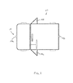
- FIG. 3 is a perspective view of a target suitable for use in calibrating a camera for a vehicle
- FIG. 4 is a perspective view of an image captured by a camera of a vehicle
- FIG. 5 is a side elevation and schematic of a vehicle with a vision system and cameras in accordance with the present invention.
- FIG. 6 is an illustration of a 360 degree top vision view as captured by the vision system and cameras of the present invention.
- FIG. 7 is a view of captured images with two cameras well aligned and two cameras misaligned
- FIG. 8A is a schematic showing a comparison of pixel resolution and a typical inclination sensor accuracy
- FIG. 8B is a schematic showing how the steradian angle ⁇ adds up from a horizontal component ⁇ b and a vertical component ⁇ c , with (b) and (c) being the resulting opposite legs of ⁇ b and ⁇ c , and (a) being the geometrical sum of (b) plus (c) and the resulting opposite leg of ⁇ ( ⁇ c equates to a in FIG. 8A );
- FIG. 9 is an example of a plan view of a vehicle with a combined human and machine vision system and five cameras and two radar sensors that provide exterior fields of view in accordance with the present invention.
- FIG. 10 is a schematic of the system of FIG. 9 , showing the vision system's architecture in accordance with the present invention.
- FIG. 11 is a flow chart showing an initialization and alignment correction algorithm in accordance with the present invention.
- FIG. 12 is a schematic showing a surround view system architecture scheme having camera alignment sensors within some or all cameras in accordance with the present invention.
- FIG. 13 is a schematic showing a surround view system architecture scheme having camera alignment sensors within some or all cameras and an additional inclination sensor within the ECU in accordance with the present invention
- FIG. 14 is a schematic showing a surround view system architecture scheme having camera alignment sensors within some or all cameras and an additional inclination sensor attached to the vehicle in accordance with the present invention.
- FIGS. 15A-D are tables showing the relation between a misalignment angle and a resulting deviation in distance.
- a vehicle 10 includes an imaging system or vision system 12 that includes at least one imaging sensor or camera 14 (such as four imaging sensors or cameras 14 a , 14 b , 14 c , 14 d at the front (or at the windshield), rear and sides of the vehicle, respectively), which capture images exterior of the vehicle ( FIG. 1 ).
- the camera 14 includes an inclination sensor 16 ( FIG. 2 ), such as a three axis inclination sensor or the like, which is operable to determine or detect or sense the orientation of the camera relative to the earth (such as the tilt or pitch or yaw or levelness of the camera).
- the vision system 12 is operable to compare an output of the inclination sensor 16 to an output of another inclination sensor of the vehicle or another inclination sensor or sensors of one or more of the other cameras mounted at the vehicle, as discussed below. Responsive to such comparison, the vision system 12 may determine when one or more of the cameras becomes misaligned, whereby the system may operate to adjust or reorient the camera towards its initial or targeted orientation or alignment or calibrated state, as also discussed below.
- Camera based systems typically require processing to correct deviations in the pitch, yaw and/or roll of the camera (extrinsic calibrations) over the life-time of the system and/or the vehicle, such as due to temperature variations or positional shifting of the camera due to vibrations and/or the like.
- processing may be required in order to provide proper image stitching or merging of images captured by multiple cameras (such as for a panoramic rearward view or such as for a surround view system or top-down or birds-eye view or the like), and/or to provide proper overlay positioning on the displayed images, such as for rear backup assist systems and the like.
- automotive cameras are calibrated offline (without driving of the vehicle, such as in the vehicle assembly or production line), using targets, such as the target 18 shown in FIG. 3 , where the positions and orientation of the target lines relative to the camera and vehicle are known.
- some automotive cameras use image processing (such as of images or image data as shown in FIG. 4 ) to detect and correct for misalignment of the camera after the camera is installed at the vehicle and while the vehicle is driven on the road.
- image processing such as of images or image data as shown in FIG. 4
- the present invention provides an inclination sensor at the camera or cameras or environmental machine vision sensor or sensors, such as, for example, a radar sensor or a lidar sensor or the like, to determine a change in the position or orientation or alignment of the camera or machine vision sensor(s) over the life of the vehicle and/or vision system and/or camera or machine vision sensor(s). If the inclination sensor is installed in the camera (or is otherwise fixedly associated with the camera) and the relation between the camera and the inclination sensor is known, the orientation of the camera to the earth can be readily measured or determined without further image processing.
- a radar sensor or a lidar sensor or the like to determine a change in the position or orientation or alignment of the camera or machine vision sensor(s) over the life of the vehicle and/or vision system and/or camera or machine vision sensor(s).
- the inclination sensor may comprise a three axis inclination sensor, and the sensor's roll, pitch and yaw may be readily obtained by the vision system circuitry or control, without requiring further complex algorithms and image processing.
- the system of the present invention includes a second inclination sensor or reference inclination sensor at the vehicle so that the system can calibrate the camera correctly to the vehicle at which it is mounted and not to a particular geographic location at the earth where the vehicle may be located.
- an inclination sensor such as a three-axis inclination sensor 16 of a camera 14 , is operable to detect changes in the yaw, pitch and roll of the sensor and camera.
- the known relation between the camera and sensor allows for readily detecting changes for each angle (yaw, pitch and roll).
- Such inclination sensors provide high accuracy and resolution, and have long-run stability (such as, for example, a deviation of less than about 0.014 degrees after more than 500 hours in operation), and provide high reproducibility (such as better than about 0.01 degrees).
- Such inclination sensors are suitable for use in automotive applications and are currently used in other automotive applications.
- FIG. 5 demonstrates how little the effect of an exemplary deviation of about 0.014 degrees (plus 0.01 degrees tolerance equals about 0.024 degrees) is in a typical rear camera range of interest of about 5 and 7 meters turns out.
- a describes a deviation angle between the camera's calibration direction and the camera's real viewing direction.
- the real viewing direction becomes measured by the inclination sensor 16 b assembled to camera 14 b (another sensor 16 c is assembled or disposed at a side mirror camera 14 c and another sensor 16 a is disposed at camera 14 a attached to vehicle 10 ).
- the deviation is just at 2.93 mm, which is much less than the typical resolution a three megapixel image sensor (1920 ⁇ 1600 pixel) has in it's center region (highest resolution area) for a rear view camera with fish eye optics having about an opening angle of about 185 degrees. Often the pixel resolution is already in the ‘cm’ area or thereabouts at that distance.
- FIG. 6 shows an illustration of a 360 degrees top vision view. These top views are generated by stitching, undistorting and dewarping of transmorphed views of single cameras to one combined view. There are stitching edges between the single cameras' borderlines. In cases where the cameras are not aligned (calibrated) well, distortion between the images become visible, especially when straight lines on the ground around the vehicle are across a stitching edge.
- FIG. 7 shows a real scene image with two cameras that are well aligned (upper left stitching area) and two cameras that are misaligned (lower right stitching area). The left out center region of the image of FIG.
- FIG. 7 is where the vehicle actually is, because the ground under the vehicle is not captured by any camera of the system.
- the misalignment is less than one pixel dot size, the distortion becomes substantially invisible or not discernible.
- 1280 ⁇ 800 pixel (SVGA) cameras were in use.
- the resulting pixel size within a stitched top view is at about 2 cm.
- FIG. 15B is a table that shows the relation between the misalignment angle and the resulting deviation in distance.
- the relation between the deviation in the given distance, the misalignment angle and the deviation is given by the geometrical mathematics: the opposing leg (deviation in the given distance) divided by the adjacent leg (distance) equates to the tangent misalignment angle.
- the arcos tangent of the division has to be used (see FIG. 15C ). Since a deviation can be horizontal and vertical (two dimensional) at one time, the deviating angle adds up geometrically to a steradian angle ⁇ (see FIG. 15D and FIGS. 8A and 8B ). As shown in FIG.
- the steradian angle ⁇ adds up from a horizontal component ⁇ b and a vertical component ⁇ c , with (b) and (c) being the resulting opposite legs of ⁇ b and ⁇ c , respectively, and (a) being the geometrical sum of (b) plus (c) and also being the resulting opposite leg of ⁇ .
- the angle ⁇ c equates to ⁇ in FIG. 8A (the vertical component of the angle).
- the distances 5 m and 7 m are listed in FIG. 15A . It becomes clear that if the camera's alignment deviation stays under about 0.229 degrees, than no pixel distortion becomes visible within a SVGA top view having about a 2 cm pixel dot size (see, for example, FIG. 8A , where the pixel resolution at a 5 m distance of a 1280 ⁇ 800 pixel sensing system of 2 cm is shown as compared to a typical inclination sensor accuracy of about 0.014 degrees+0.01 degrees, with the scaling in FIG. 8A being exaggerated to improve the readability). At megapixel cameras (1920 ⁇ 1600 pixel) the pixel dot size is at about 1 cm within a top view image with 5 m as visible area around a vehicle.
- This ratio shows that the accuracy of inclination sensors (of about 0.014 degrees+/ ⁇ 0.01 degrees) is about five times higher in megapixel top view vision systems and about ten times higher than necessary to calibrate the visions system's cameras accurately enough to substantially prevent or limit visible distortion (less than 1 pixel).
- the most economic choice would be to pick the least accurate sensor in angular accuracy which still allows the system to calibrate the vision system's cameras accurate enough so that the deviation at the furthest visible point within a top view screen is still less than one pixel.
- the visible area around the car is limited. Typically, the visible area in front and behind the car is at about 5 meters (limited longitudinal extension) and the visible area at the side of the car is typically at about 3 meters (limited latitudinal extension), with the longitudinal extension being generally orthogonal to the longitudinal extension (the longitudinal extension typically is the longer one). Points at the far corners are the furthest.
- the inclination sensor angular (steradian) accuracy limit is given by the arcos tangent of the pixel size resolution at the furthest visible point at the screen divided by the distance to that point (see FIG. 15D ).
- tangent alpha is equal to the opposite leg of the triangle or distance divided by the adjacent leg of the triangle (so the deviation in the distance)
- the system is able to compare which deviation in the distance would become captured by one pixel. This is why the longest distance which is visible within the top view (typically the longitudinal distance, which is typically around 5 m) is preferably selected.
- the angular resolution of an inclination sensor is more accurate than the arcus tangent of the highest possible deviation in distance divided by the distance, the misalignment of a camera does not become visible. Since a deviation can occur with mixed vertical and horizontal components at the same time, the system may utilize the steradian angle ⁇ in the tangential equation.
- a single camera vision system of the present invention may, for example, have an inclination sensor at the camera and a second inclination sensor at the vehicle ( 16 d in FIG. 5 ).
- the second inclination sensor may be disposed within the ECU or anywhere at the vehicle (such as, for example, at the head unit of the vehicle or any other suitable location at the vehicle), as long as its initial orientation relative to the initial orientation of the camera's inclination sensor is known.
- the system may compare the outputs of the two inclination sensors and may thus determine when there is a change in orientation of the camera's inclination sensor and thus a change in orientation of the camera.
- the system may generate an alert (such as to indicate that a particular camera is misaligned) or may adjust the camera or image data captured by the camera (such as via a physical adjustment of the camera orientation or such as via image processing or the like) to account for or correct for the detected or determined misalignment or change in orientation of the camera.
- an alert such as to indicate that a particular camera is misaligned
- the system may adjust the camera or image data captured by the camera (such as via a physical adjustment of the camera orientation or such as via image processing or the like) to account for or correct for the detected or determined misalignment or change in orientation of the camera.
- a multi-camera vision system may have multiple cameras disposed at the vehicle with exterior fields of view around the vehicle (such as shown in FIGS. 1, 5, 6, 7 and 9 ), with most of the cameras having an inclination sensor associated therewith or attached thereto (for example, and as shown in FIGS. 9 and 10 , a combined human and machine vision system may comprise or include one or more, such as two, radar sensors in addition to a four or five camera system).
- an additional inclination sensor is not needed at the vehicle but such a sensor is optional as an additional reference (see reference 16 d in FIG. 5 and see FIG. 14 ).
- the initial outputs of the cameras when properly oriented and aligned and calibrated will be received and/or input and/or known by the vision system control.
- the vision system control knowing the initial outputs of the cameras' inclination sensors and thus the initial relative orientations of the cameras, can monitor the outputs of the inclination sensors and determine when one of them changes relative to the others. Responsive to such a detection or determination, the control may generate an alert (such as to indicate that a particular camera is misaligned) or may adjust the physical orientation of the misaligned camera or adjust the image processing of the image data captured by the misaligned camera or the like, in order to account for the misalignment.
- an alert such as to indicate that a particular camera is misaligned
- the multi-camera vision system thus may determine misalignment of a camera at the vehicle via the inclinometers at the cameras and an additional algorithm.
- the algorithm may process the sensor outputs and may determine, responsive to a relative change in the outputs of the sensors (that would be indicative of the orientation of one of the sensors changing relative to the vehicle and that would not be merely indicative of the vehicle orientation changing), which sensor or sensors is/are the reference sensor/sensors and which sensor is misaligned.
- the system may determine which of the sensors to use as the reference and compare the outputs of the other sensors to the reference sensor to determine the alignment or misalignment.
- a vehicle 10 includes or has a combined human and machine vision system, which includes five high dynamic range (HDR) cameras, such as a front right side corner camera 14 a ′, a front left side corner camera 14 a ′′, a rear or rearward facing center camera 14 b and wide angle left and right side cameras 14 c , 14 d that provide exterior fields of view in accordance with the present invention (optionally, the system may include a front or forward facing center camera 14 a ).
- the system also includes a front radar sensor 140 and a rear radar sensor 141 .
- FIG. 10 is a schematic of the specific example of FIG. 9 showing the vision system's architecture in accordance with the present invention.
- the Oculus Module may comprise a system-on-chip or Electronic Control Unit (ECU).
- the LVDS data line comprises a full duplex.
- the front facing camera may comprise an EPM3TM camera or the like, and may have or utilize or be associated with an image processor, such as am EyeQTM or EyeQ2TM or EyeQ3TM processor, such as are provided by Mobileye® (where the image processor utilizes object detection software or the like in processing image data captured by the camera or cameras), or the like.
- the image data captured by the five cameras (such as five HDR cameras) may be communicated to the module via a video bus communication link 2 , and the module may provide a control signal 5 to the cameras.
- a data bus (such as a CAN or LIN or Ethernet data bus or network or an HSCAN data bus or network) may be utilized to communicate signals between the module and the radar sensors (and optionally the front facing camera) and/or the vehicle.
- the system may generate control signals that provide braking control and/or vehicle steering control responsive to the captured image data and outputs of the radar sensors.
- FIG. 11 An exemplary initialization and alignment correction algorithm according to the present invention is shown in the chart of FIG. 11 .
- An according surround view system architecture scheme having camera alignment sensors (inclinometers) within some or all of the cameras is shown in the chart of FIG. 12 .
- FIG. 13 is a chart showing a preferred embodiment of the present invention's system architecture having an additional inclination sensor assembled within the ECU for providing a reference normal signal in addition to inclination sensor signals of the visions system's cameras.
- FIG. 14 is a chart showing an example of the architecture having the additional inclination sensor attached to the vehicle (see reference 16 d in FIG.
- a (vehicle's level) reference normal signal in addition to inclination sensor signals of the visions system's camera via CAN or LIN bus interfaces (or other suitable communication network or link or Ethernet communication link or the like) to the vision system control or MCU.
- the camera alignment correction/calibration algorithm may not always be allowed to run due to manufacturer requirements. For example, there may be limited modes in which a calibration run is enabled. Also, there might be limitations in the minimum required start up time or shut down time or to energy consumption while idling. The transfer channels might have limited capacity as well. To cope with these matters, the transfer of the three axis (vector) of an inclinometer may be transferred within the SYNC gap between images during run time or incorporate into the image stream, such as by utilizing aspects of the systems described in U.S. provisional application Ser. No. 61/567,446, filed Dec. 6, 2011, which is hereby incorporated herein by reference in its entirety.
- the inclination vector data may be stored in the MCU so as to be present at times when a calibration cycle is enabled.
- the vision system may include a display screen that is disposed in the vehicle (such as at an interior rearview mirror assembly or windshield electronics module or the like in the cabin of the vehicle and at or near the in-cabin surface of the vehicle windshield) and viewable by the driver of the vehicle.
- the vision system is operable to display images representative of captured image data on the display screen.
- the vision system is operable in a virtual top view vision mode and, when operating in the top view vision mode, the processing system processes image data captured by the imaging sensors to at least one of combine and manipulate the image data, and, when operating in the top view vision mode, the vision system displays an exterior scene (such as via the combination and/or manipulation or stitching or merging of the image data captured by the plurality of cameras) around the vehicle.
- the displayed exterior scene is around the vehicle and may have a first limited extension in one dimension (such as forwardly of the vehicle and along the field of view of the forward facing camera) and a second limited extension in a second orthogonal dimension (such as sidewardly of the vehicle), wherein the result of a tangent steradian accuracy of the at least one inclination sensor divided by a longer one of the first and second limited extensions is greater than the highest resolution of at least one of the image sensors along the longer limited extension's path.
- a first limited extension in one dimension such as forwardly of the vehicle and along the field of view of the forward facing camera
- a second limited extension in a second orthogonal dimension such as sidewardly of the vehicle
- the present invention provides a means for determining a misalignment of a camera at a vehicle. If the intrinsic parameters of a camera are measured together with the inclinometer of the camera (such as inside the camera or at the camera), the camera may be aligned to the vehicle without any target in the camera's field of view and without any image processing of images captured by the camera. The changes of the camera-to-vehicle alignment over the vehicle or camera or system life or due to temperature variations or the like can be readily corrected using relatively simple algorithms (either while the vehicle is being driven on a road or when the vehicle is parked or otherwise not in use).
- the system of the present invention allows for replacement of a damaged camera without requiring special service calibration procedures (for example, no drives or targets are needed to calibrate/align the new camera). Also, the present invention does not require any complicated preconditions when using image processing algorithms (dependencies to other software modules such as a camera control function or the like).
- the system of the present invention thus utilizes two or more inclination sensors or level sensors, and the two or more inclination sensors may be part of or associated with respective cameras, or one or more inclination sensors may be associated with a respective one or more cameras and another inclination sensor may be disposed at the vehicle separate from any camera.
- the system may utilize an inclination sensor that is already part of or incorporated at the vehicle, such as a level sensor or the like that is used by a leveling system of the vehicle to adjust the suspension to level the vehicle.
- the system utilizes two inclination sensors to detect a misalignment or threshold degree of misalignment of one or more cameras (having an inclination sensor associated therewith) mounted at the vehicle, such as at an exterior rearview mirror assembly of the vehicle and/or at a rear portion of the vehicle and/or at a front portion of the vehicle and/or at an interior rearview mirror assembly and/or windshield electronics module of the vehicle.
- the system of the present invention may be particularly useful when the camera and inclination sensor or inclinometer are disposed or used in an exterior rearview or sideview mirror assembly, and the system of the present invention may utilize aspects of (or may operate in conjunction with or separate from) the systems described in U.S. Pat. Nos.
- the imaging sensor and its photosensor array may comprise any suitable camera or sensing device, such as, for example, an array of a plurality of photosensor elements arranged in 640 columns and 480 rows (a 640 ⁇ 480 imaging array) or more (such as discussed above), with a respective lens focusing images onto respective portions of the array.
- the photosensor array may comprise a plurality of photosensor elements arranged in a photosensor array having rows and columns.
- the logic and control circuit of the imaging sensor may function in any known manner, such as in the manner described in U.S. Pat. Nos. 5,550,677; 5,877,897; 6,498,620; 5,670,935; 5,796,094; 6,396,397, and/or U.S. patent application Ser. No. 13/534,657, filed Jun. 27, 2012, and/or U.S. provisional applications, Ser. No. 61/666,146, filed Jun. 29, 2012; Ser. No. 61/653,665, filed May 31, 2012; Ser. No. 61/653,664, filed May 31, 2012; Ser. No. 61/650,667, filed May 23, 2012; Ser. No. 61/624,507, filed Apr. 16, 2012; Ser. No.
- the system may communicate with other communication systems via any suitable means, such as by utilizing aspects of the systems described in PCT Application No. PCT/US10/038477, filed Jun. 14, 2010, and/or U.S. patent application Ser. No.
- the imaging device and control and image processor and any associated illumination source may comprise any suitable components, and may utilize aspects of the cameras and vision systems described in U.S. Pat. Nos. 5,550,677; 5,877,897; 6,498,620; 5,670,935; 5,796,094; 6,396,397; 6,806,452; 6,690,268; 7,005,974; 7,123,168; 7,004,606; 6,946,978; 7,038,577; 6,353,392; 6,320,176; 6,313,454; and 6,824,281, and/or International Publication No. WO 2010/099416, published Sep. 2, 2010, and/or PCT Application No. PCT/US10/47256, filed Aug.
- the camera or cameras may comprise any suitable cameras or imaging sensors or camera modules, and may utilize aspects of the cameras or sensors described in U.S. patent application Ser. No. 12/091,359, filed Apr. 24, 2008 and published Oct.
- the imaging array sensor may comprise any suitable sensor, and may utilize various imaging sensors or imaging array sensors or cameras or the like, such as a CMOS imaging array sensor, a CCD sensor or other sensors or the like, such as the types described in U.S. Pat. Nos.
- the camera module and circuit chip or board and imaging sensor may be implemented and operated in connection with various vehicular vision-based systems, and/or may be operable utilizing the principles of such other vehicular systems, such as a vehicle headlamp control system, such as the type disclosed in U.S. Pat. Nos. 5,796,094; 6,097,023; 6,320,176; 6,559,435; 6,831,261; 7,004,606; 7,339,149; and/or 7,526,103, which are all hereby incorporated herein by reference in their entireties, a rain sensor, such as the types disclosed in commonly assigned U.S. Pat. Nos.
- a vehicle vision system such as a forwardly, sidewardly or rearwardly directed vehicle vision system utilizing principles disclosed in U.S. Pat. Nos.
- a reverse or sideward imaging system such as for a lane change assistance system or lane departure warning system or for a blind spot or object detection system, such as imaging or detection systems of the types disclosed in U.S. Pat. Nos. 7,881,496; 7,720,580; 7,038,577; 5,929,786 and/or 5,786,772, and/or U.S. provisional applications, Ser. No. 60/628,709, filed Nov. 17, 2004; Ser. No. 60/614,644, filed Sep. 30, 2004; Ser. No. 60/618,686, filed Oct. 14, 2004; Ser. No. 60/638,687, filed Dec.
- a video device for internal cabin surveillance and/or video telephone function such as disclosed in U.S. Pat. Nos. 5,760,962; 5,877,897; 6,690,268; and/or 7,370,983, and/or U.S. patent application Ser. No. 10/538,724, filed Jun. 13, 2005 and published Mar. 9, 2006 as U.S. Publication No. US-2006-0050018, which are hereby incorporated herein by reference in their entireties, a traffic sign recognition system, a system for determining a distance to a leading or trailing vehicle or object, such as a system utilizing the principles disclosed in U.S. Pat. Nos. 6,396,397 and/or 7,123,168, which are hereby incorporated herein by reference in their entireties, and/or the like.
- the circuit board or chip may include circuitry for the imaging array sensor and or other electronic accessories or features, such as by utilizing compass-on-a-chip or EC driver-on-a-chip technology and aspects such as described in U.S. Pat. No. 7,255,451 and/or U.S. Pat. No. 7,480,149; and/or U.S. patent application Ser. No. 11/226,628, filed Sep. 14, 2005 and published Mar. 23, 2006 as U.S. Publication No. US-2006-0061008, and/or Ser. No. 12/578,732, filed Oct. 14, 2009 and published Apr. 22, 2010 as U.S. Publication No. US-2010-0097469, which are hereby incorporated herein by reference in their entireties.
- the vision system may include a display for displaying images captured by one or more of the imaging sensors for viewing by the driver of the vehicle while the driver is normally operating the vehicle.
- the vision system may include a video display device disposed at or in the interior rearview mirror assembly of the vehicle, such as by utilizing aspects of the video mirror display systems described in U.S. Pat. No. 6,690,268 and/or U.S. patent application Ser. No. 13/333,337, filed Dec. 21, 2011, now U.S. Pat. No. 9,264,672, which are hereby incorporated herein by reference in their entireties.
- the video mirror display may comprise any suitable devices and systems and optionally may utilize aspects of the compass display systems described in U.S. Pat. Nos.
- the video mirror display screen or device may be operable to display images captured by a rearward viewing camera of the vehicle during a reversing maneuver of the vehicle (such as responsive to the vehicle gear actuator being placed in a reverse gear position or the like) to assist the driver in backing up the vehicle, and optionally may be operable to display the compass heading or directional heading character or icon when the vehicle is not undertaking a reversing maneuver, such as when the vehicle is being driven in a forward direction along a road (such as by utilizing aspects of the display system described in PCT Application No. PCT/US2011/056295, filed Oct. 14, 2011 and published Apr.
- the display screen or display device may be disposed at or in the interior rearview mirror assembly or may comprise a navigational display of the vehicle, such as may be disposed at the instrument panel or console of the vehicle or the like.
- the vision system (utilizing a forward and/or rearward facing camera and other cameras disposed at the vehicle with exterior fields of view) comprises and utilizes a plurality of cameras (such as utilizing a rearward facing camera and sidewardly facing cameras and a forwardly facing camera disposed at the vehicle), and provides a display of a top-down view or birds-eye view of the vehicle or a surround view at the vehicle, such as by utilizing aspects of the vision systems described in PCT Application No. PCT/US10/25545, filed Feb. 26, 2010 and published on Sep. 2, 2010 as International Publication No. WO 2010/099416, and/or PCT Application No. PCT/US10/47256, filed Aug. 31, 2010 and published Mar. 10, 2011 as International Publication No.
- the video mirror display may be disposed rearward of and behind the reflective element assembly and may comprise a display such as the types disclosed in U.S. Pat. Nos. 5,530,240; 6,329,925; 7,855,755; 7,626,749; 7,581,859; 7,338,177; 7,274,501; 7,255,451; 7,195,381; 7,184,190; 5,668,663; 5,724,187 and/or 6,690,268, and/or in U.S. patent application Ser. No. 11/226,628, filed Sep. 14, 2005 and published Mar. 23, 2006 as U.S. Publication No. US-2006-0061008; and/or Ser. No. 10/538,724, filed Jun. 13, 2005 and published Mar.
- a display such as the types disclosed in U.S. Pat. Nos. 5,530,240; 6,329,925; 7,855,755; 7,626,749; 7,581,859; 7,338,177; 7,274,501; 7,255,451; 7,195,381;
- the display is viewable through the reflective element when the display is activated to display information.
- the display element may be any type of display element, such as a vacuum fluorescent (VF) display element, a light emitting diode (LED) display element, such as an organic light emitting diode (OLED) or an inorganic light emitting diode, an electroluminescent (EL) display element, a liquid crystal display (LCD) element, a video screen display element or backlit thin film transistor (TFT) display element or the like, and may be operable to display various information (as discrete characters, icons or the like, or in a multi-pixel manner) to the driver of the vehicle, such as passenger side inflatable restraint (PSIR) information, tire pressure status, and/or the like.
- PSIR passenger side inflatable restraint
- the mirror assembly and/or display may utilize aspects described in U.S. Pat. Nos. 7,184,190; 7,255,451; 7,446,924 and/or 7,338,177, which are all hereby incorporated herein by reference in their entireties.
- the thicknesses and materials of the coatings on the substrates of the reflective element may be selected to provide a desired color or tint to the mirror reflective element, such as a blue colored reflector, such as is known in the art and such as described in U.S. Pat. Nos. 5,910,854; 6,420,036; and/or 7,274,501, which are hereby incorporated herein by reference in their entireties.
- the display or displays and any associated user inputs may be associated with various accessories or systems, such as, for example, a tire pressure monitoring system or a passenger air bag status or a garage door opening system or a telematics system or any other accessory or system of the mirror assembly or of the vehicle or of an accessory module or console of the vehicle, such as an accessory module or console of the types described in U.S. Pat. Nos. 7,289,037; 6,877,888; 6,824,281; 6,690,268; 6,672,744; 6,386,742; and 6,124,886, and/or U.S. patent application Ser. No. 10/538,724, filed Jun. 13, 2005 and published Mar. 9, 2006 as U.S. Publication No. US-2006-0050018, which are hereby incorporated herein by reference in their entireties.
- accessories or systems such as, for example, a tire pressure monitoring system or a passenger air bag status or a garage door opening system or a telematics system or any other accessory or system of the mirror assembly or
- the display or displays may comprise a video display and may utilize aspects of the video display devices or modules described in U.S. Pat. Nos. 6,690,268; 7,184,190; 7,274,501; 7,370,983; 7,446,650; and/or 7,855,755, and/or U.S. patent application Ser. No. 10/538,724, filed Jun. 13, 2005 and published Mar. 9, 2006 as U.S. Publication No. US-2006-0050018, which are all hereby incorporated herein by reference in their entireties.
- the video display may be operable to display images captured by one or more imaging sensors or cameras at the vehicle.
Abstract
A vision system for a vehicle includes at least one imaging sensor disposed at the vehicle and having an exterior field of view. The imaging sensor is operable to capture image data. The imaging sensor includes or is associated with an inclination sensor. At least one other inclination sensor is disposed at the vehicle. A processing system is operable to process outputs of the inclination sensors to determine an alignment or misalignment of the at least one imaging sensor at the vehicle.
Description
The present application is a 371 national phase filing of PCT Application No. PCT/US2012/048880, filed Jul. 30, 2012, which claims the filing benefits of U.S. provisional application Ser. No. 61/513,745, filed Aug. 1, 2011, which is hereby incorporated herein by reference in its entirety.
The present invention relates to imaging systems or vision systems for vehicles and, more particularly, to a vision system that includes at least one imaging device or camera for capturing images exteriorly of the vehicle.
Use of imaging sensors in vehicle imaging systems is common and known. Examples of such known systems are described in U.S. Pat. Nos. 5,949,331; 5,670,935; and/or 5,550,677, which are hereby incorporated herein by reference in their entireties. Vehicle vision camera service calibration algorithms are common and known. Examples of such known systems are described in PCT Publication No. WO 2011/085489, which is hereby incorporated herein by reference in its entirety.
The present invention provides a vision system or imaging system for a vehicle that utilizes one or more cameras to capture images exterior of the vehicle, and provides for alignment or alignment adjustment of the camera or cameras to correct deviations in the camera's alignment over the life of the vision system. Optionally, the alignment of other environmental sensors for machine vision may be determined and adjusted as well.
The camera or cameras or machine vision sensor or sensors of the vehicle may include an inclination sensor, such as a three axis inclination sensor, to detect the orientation of the camera relative to the earth. An output of the inclination sensor may be compared to an output of another inclination sensor of the vehicle or of one or more other cameras on the vehicle, and the system may determine when the camera may be misaligned, whereby the camera may be adjusted towards its initial or targeted orientation or alignment.
These and other objects, advantages, purposes and features of the present invention will become apparent upon review of the following specification in conjunction with the drawings.
Referring now to the drawings and the illustrative embodiments depicted therein, a vehicle 10 includes an imaging system or vision system 12 that includes at least one imaging sensor or camera 14 (such as four imaging sensors or cameras 14 a, 14 b, 14 c, 14 d at the front (or at the windshield), rear and sides of the vehicle, respectively), which capture images exterior of the vehicle (FIG. 1 ). The camera 14 includes an inclination sensor 16 (FIG. 2 ), such as a three axis inclination sensor or the like, which is operable to determine or detect or sense the orientation of the camera relative to the earth (such as the tilt or pitch or yaw or levelness of the camera). The vision system 12 is operable to compare an output of the inclination sensor 16 to an output of another inclination sensor of the vehicle or another inclination sensor or sensors of one or more of the other cameras mounted at the vehicle, as discussed below. Responsive to such comparison, the vision system 12 may determine when one or more of the cameras becomes misaligned, whereby the system may operate to adjust or reorient the camera towards its initial or targeted orientation or alignment or calibrated state, as also discussed below.
Camera based systems (such as multi-camera systems like a surround view system or the like, or a rear view camera or the like) typically require processing to correct deviations in the pitch, yaw and/or roll of the camera (extrinsic calibrations) over the life-time of the system and/or the vehicle, such as due to temperature variations or positional shifting of the camera due to vibrations and/or the like. Such processing may be required in order to provide proper image stitching or merging of images captured by multiple cameras (such as for a panoramic rearward view or such as for a surround view system or top-down or birds-eye view or the like), and/or to provide proper overlay positioning on the displayed images, such as for rear backup assist systems and the like.
Typically, automotive cameras are calibrated offline (without driving of the vehicle, such as in the vehicle assembly or production line), using targets, such as the target 18 shown in FIG. 3 , where the positions and orientation of the target lines relative to the camera and vehicle are known. Optionally, some automotive cameras use image processing (such as of images or image data as shown in FIG. 4 ) to detect and correct for misalignment of the camera after the camera is installed at the vehicle and while the vehicle is driven on the road. For example, such alignment detection and correction via image processing is described in U.S. Pat. Nos. 7,991,522; 7,877,175 and 7,720,580, and/or R. Hartley and A. Zisserman, “Multiple View Geometry in Computer Vision”, Cambridge, ISBN 978-0-521-54051-3, which are all hereby incorporated herein by reference in their entireties. Such image processing techniques work well for their intended purposes, but may require additional processing based online (during driving) calibration algorithms, and thus may require additional processing power (such as tracking, vanishing point estimation, trajectory calculations and the like).
The present invention provides an inclination sensor at the camera or cameras or environmental machine vision sensor or sensors, such as, for example, a radar sensor or a lidar sensor or the like, to determine a change in the position or orientation or alignment of the camera or machine vision sensor(s) over the life of the vehicle and/or vision system and/or camera or machine vision sensor(s). If the inclination sensor is installed in the camera (or is otherwise fixedly associated with the camera) and the relation between the camera and the inclination sensor is known, the orientation of the camera to the earth can be readily measured or determined without further image processing. For example, the inclination sensor may comprise a three axis inclination sensor, and the sensor's roll, pitch and yaw may be readily obtained by the vision system circuitry or control, without requiring further complex algorithms and image processing. Because the vehicle-to-earth relationship is not fixed (the vehicle travels on different roads or surfaces with different tilts, slopes, etc.), the system of the present invention includes a second inclination sensor or reference inclination sensor at the vehicle so that the system can calibrate the camera correctly to the vehicle at which it is mounted and not to a particular geographic location at the earth where the vehicle may be located.
For example, and with reference to FIG. 2 , an inclination sensor, such as a three-axis inclination sensor 16 of a camera 14, is operable to detect changes in the yaw, pitch and roll of the sensor and camera. The known relation between the camera and sensor allows for readily detecting changes for each angle (yaw, pitch and roll). With reference to FIG. 2 , the angle β is known due to the relation of the inclination sensor to the camera (and may be fixed), and thus a change of the pitch (for example) of the camera may be determined or measured responsive to the inclination sensor output (where the pitch is determined as Y=β−α). Such inclination sensors provide high accuracy and resolution, and have long-run stability (such as, for example, a deviation of less than about 0.014 degrees after more than 500 hours in operation), and provide high reproducibility (such as better than about 0.01 degrees). Such inclination sensors are suitable for use in automotive applications and are currently used in other automotive applications.
The example in FIG. 5 demonstrates how little the effect of an exemplary deviation of about 0.014 degrees (plus 0.01 degrees tolerance equals about 0.024 degrees) is in a typical rear camera range of interest of about 5 and 7 meters turns out. In this example a describes a deviation angle between the camera's calibration direction and the camera's real viewing direction. The real viewing direction becomes measured by the inclination sensor 16 b assembled to camera 14 b (another sensor 16 c is assembled or disposed at a side mirror camera 14 c and another sensor 16 a is disposed at camera 14 a attached to vehicle 10). In the (rear) distance of seven meters, the deviation is just at 2.93 mm, which is much less than the typical resolution a three megapixel image sensor (1920×1600 pixel) has in it's center region (highest resolution area) for a rear view camera with fish eye optics having about an opening angle of about 185 degrees. Often the pixel resolution is already in the ‘cm’ area or thereabouts at that distance.
In virtual top view vision systems, often a radius of maximal about 5 m is visible around a vehicle. FIG. 6 shows an illustration of a 360 degrees top vision view. These top views are generated by stitching, undistorting and dewarping of transmorphed views of single cameras to one combined view. There are stitching edges between the single cameras' borderlines. In cases where the cameras are not aligned (calibrated) well, distortion between the images become visible, especially when straight lines on the ground around the vehicle are across a stitching edge. FIG. 7 shows a real scene image with two cameras that are well aligned (upper left stitching area) and two cameras that are misaligned (lower right stitching area). The left out center region of the image of FIG. 7 is where the vehicle actually is, because the ground under the vehicle is not captured by any camera of the system. When the misalignment is less than one pixel dot size, the distortion becomes substantially invisible or not discernible. In the shown example of FIG. 7 , 1280×800 pixel (SVGA) cameras were in use. The resulting pixel size within a stitched top view is at about 2 cm.
The distances 5 m and 7 m are listed in FIG. 15A . It becomes clear that if the camera's alignment deviation stays under about 0.229 degrees, than no pixel distortion becomes visible within a SVGA top view having about a 2 cm pixel dot size (see, for example, FIG. 8A , where the pixel resolution at a 5 m distance of a 1280×800 pixel sensing system of 2 cm is shown as compared to a typical inclination sensor accuracy of about 0.014 degrees+0.01 degrees, with the scaling in FIG. 8A being exaggerated to improve the readability). At megapixel cameras (1920×1600 pixel) the pixel dot size is at about 1 cm within a top view image with 5 m as visible area around a vehicle. This ratio shows that the accuracy of inclination sensors (of about 0.014 degrees+/−0.01 degrees) is about five times higher in megapixel top view vision systems and about ten times higher than necessary to calibrate the visions system's cameras accurately enough to substantially prevent or limit visible distortion (less than 1 pixel).
In practice, the most economic choice would be to pick the least accurate sensor in angular accuracy which still allows the system to calibrate the vision system's cameras accurate enough so that the deviation at the furthest visible point within a top view screen is still less than one pixel. Within a top view system, the visible area around the car is limited. Typically, the visible area in front and behind the car is at about 5 meters (limited longitudinal extension) and the visible area at the side of the car is typically at about 3 meters (limited latitudinal extension), with the longitudinal extension being generally orthogonal to the longitudinal extension (the longitudinal extension typically is the longer one). Points at the far corners are the furthest. The inclination sensor angular (steradian) accuracy limit is given by the arcos tangent of the pixel size resolution at the furthest visible point at the screen divided by the distance to that point (see FIG. 15D ).
Because tangent alpha is equal to the opposite leg of the triangle or distance divided by the adjacent leg of the triangle (so the deviation in the distance), the system is able to compare which deviation in the distance would become captured by one pixel. This is why the longest distance which is visible within the top view (typically the longitudinal distance, which is typically around 5 m) is preferably selected. As long the angular resolution of an inclination sensor is more accurate than the arcus tangent of the highest possible deviation in distance divided by the distance, the misalignment of a camera does not become visible. Since a deviation can occur with mixed vertical and horizontal components at the same time, the system may utilize the steradian angle θ in the tangential equation.
A single camera vision system of the present invention (such as a rear vision system having a rearward facing camera at a rear portion of the vehicle) may, for example, have an inclination sensor at the camera and a second inclination sensor at the vehicle (16 d in FIG. 5 ). The second inclination sensor may be disposed within the ECU or anywhere at the vehicle (such as, for example, at the head unit of the vehicle or any other suitable location at the vehicle), as long as its initial orientation relative to the initial orientation of the camera's inclination sensor is known. During use of the vehicle and vision system, the system may compare the outputs of the two inclination sensors and may thus determine when there is a change in orientation of the camera's inclination sensor and thus a change in orientation of the camera. Responsive to such a detection or determination, the system may generate an alert (such as to indicate that a particular camera is misaligned) or may adjust the camera or image data captured by the camera (such as via a physical adjustment of the camera orientation or such as via image processing or the like) to account for or correct for the detected or determined misalignment or change in orientation of the camera.
Optionally, a multi-camera vision system (such as for a surround-view system or the like) may have multiple cameras disposed at the vehicle with exterior fields of view around the vehicle (such as shown in FIGS. 1, 5, 6, 7 and 9 ), with most of the cameras having an inclination sensor associated therewith or attached thereto (for example, and as shown in FIGS. 9 and 10 , a combined human and machine vision system may comprise or include one or more, such as two, radar sensors in addition to a four or five camera system). In such an application, an additional inclination sensor is not needed at the vehicle but such a sensor is optional as an additional reference (see reference 16 d in FIG. 5 and see FIG. 14 ). The initial outputs of the cameras when properly oriented and aligned and calibrated will be received and/or input and/or known by the vision system control. Thus, the vision system control, knowing the initial outputs of the cameras' inclination sensors and thus the initial relative orientations of the cameras, can monitor the outputs of the inclination sensors and determine when one of them changes relative to the others. Responsive to such a detection or determination, the control may generate an alert (such as to indicate that a particular camera is misaligned) or may adjust the physical orientation of the misaligned camera or adjust the image processing of the image data captured by the misaligned camera or the like, in order to account for the misalignment. The multi-camera vision system thus may determine misalignment of a camera at the vehicle via the inclinometers at the cameras and an additional algorithm. The algorithm may process the sensor outputs and may determine, responsive to a relative change in the outputs of the sensors (that would be indicative of the orientation of one of the sensors changing relative to the vehicle and that would not be merely indicative of the vehicle orientation changing), which sensor or sensors is/are the reference sensor/sensors and which sensor is misaligned. The system may determine which of the sensors to use as the reference and compare the outputs of the other sensors to the reference sensor to determine the alignment or misalignment.
As shown in FIG. 9 , a vehicle 10 includes or has a combined human and machine vision system, which includes five high dynamic range (HDR) cameras, such as a front right side corner camera 14 a′, a front left side corner camera 14 a″, a rear or rearward facing center camera 14 b and wide angle left and right side cameras 14 c, 14 d that provide exterior fields of view in accordance with the present invention (optionally, the system may include a front or forward facing center camera 14 a). The system also includes a front radar sensor 140 and a rear radar sensor 141. FIG. 10 is a schematic of the specific example of FIG. 9 showing the vision system's architecture in accordance with the present invention. The Oculus Module may comprise a system-on-chip or Electronic Control Unit (ECU). In the illustrated embodiment, the LVDS data line comprises a full duplex. The front facing camera may comprise an EPM3™ camera or the like, and may have or utilize or be associated with an image processor, such as am EyeQ™ or EyeQ2™ or EyeQ3™ processor, such as are provided by Mobileye® (where the image processor utilizes object detection software or the like in processing image data captured by the camera or cameras), or the like. The image data captured by the five cameras (such as five HDR cameras) may be communicated to the module via a video bus communication link 2, and the module may provide a control signal 5 to the cameras. A data bus (such as a CAN or LIN or Ethernet data bus or network or an HSCAN data bus or network) may be utilized to communicate signals between the module and the radar sensors (and optionally the front facing camera) and/or the vehicle. The system may generate control signals that provide braking control and/or vehicle steering control responsive to the captured image data and outputs of the radar sensors.
An exemplary initialization and alignment correction algorithm according to the present invention is shown in the chart of FIG. 11 . An according surround view system architecture scheme having camera alignment sensors (inclinometers) within some or all of the cameras is shown in the chart of FIG. 12 . FIG. 13 is a chart showing a preferred embodiment of the present invention's system architecture having an additional inclination sensor assembled within the ECU for providing a reference normal signal in addition to inclination sensor signals of the visions system's cameras. FIG. 14 is a chart showing an example of the architecture having the additional inclination sensor attached to the vehicle (see reference 16 d in FIG. 5 ) providing a (vehicle's level) reference normal signal in addition to inclination sensor signals of the visions system's camera via CAN or LIN bus interfaces (or other suitable communication network or link or Ethernet communication link or the like) to the vision system control or MCU.
The camera alignment correction/calibration algorithm may not always be allowed to run due to manufacturer requirements. For example, there may be limited modes in which a calibration run is enabled. Also, there might be limitations in the minimum required start up time or shut down time or to energy consumption while idling. The transfer channels might have limited capacity as well. To cope with these matters, the transfer of the three axis (vector) of an inclinometer may be transferred within the SYNC gap between images during run time or incorporate into the image stream, such as by utilizing aspects of the systems described in U.S. provisional application Ser. No. 61/567,446, filed Dec. 6, 2011, which is hereby incorporated herein by reference in its entirety. The inclination vector data may be stored in the MCU so as to be present at times when a calibration cycle is enabled.
The vision system may include a display screen that is disposed in the vehicle (such as at an interior rearview mirror assembly or windshield electronics module or the like in the cabin of the vehicle and at or near the in-cabin surface of the vehicle windshield) and viewable by the driver of the vehicle. The vision system is operable to display images representative of captured image data on the display screen. The vision system is operable in a virtual top view vision mode and, when operating in the top view vision mode, the processing system processes image data captured by the imaging sensors to at least one of combine and manipulate the image data, and, when operating in the top view vision mode, the vision system displays an exterior scene (such as via the combination and/or manipulation or stitching or merging of the image data captured by the plurality of cameras) around the vehicle. The displayed exterior scene is around the vehicle and may have a first limited extension in one dimension (such as forwardly of the vehicle and along the field of view of the forward facing camera) and a second limited extension in a second orthogonal dimension (such as sidewardly of the vehicle), wherein the result of a tangent steradian accuracy of the at least one inclination sensor divided by a longer one of the first and second limited extensions is greater than the highest resolution of at least one of the image sensors along the longer limited extension's path.
Thus, the present invention provides a means for determining a misalignment of a camera at a vehicle. If the intrinsic parameters of a camera are measured together with the inclinometer of the camera (such as inside the camera or at the camera), the camera may be aligned to the vehicle without any target in the camera's field of view and without any image processing of images captured by the camera. The changes of the camera-to-vehicle alignment over the vehicle or camera or system life or due to temperature variations or the like can be readily corrected using relatively simple algorithms (either while the vehicle is being driven on a road or when the vehicle is parked or otherwise not in use). Also, the system of the present invention allows for replacement of a damaged camera without requiring special service calibration procedures (for example, no drives or targets are needed to calibrate/align the new camera). Also, the present invention does not require any complicated preconditions when using image processing algorithms (dependencies to other software modules such as a camera control function or the like).
The system of the present invention thus utilizes two or more inclination sensors or level sensors, and the two or more inclination sensors may be part of or associated with respective cameras, or one or more inclination sensors may be associated with a respective one or more cameras and another inclination sensor may be disposed at the vehicle separate from any camera. For example, the system may utilize an inclination sensor that is already part of or incorporated at the vehicle, such as a level sensor or the like that is used by a leveling system of the vehicle to adjust the suspension to level the vehicle. The system utilizes two inclination sensors to detect a misalignment or threshold degree of misalignment of one or more cameras (having an inclination sensor associated therewith) mounted at the vehicle, such as at an exterior rearview mirror assembly of the vehicle and/or at a rear portion of the vehicle and/or at a front portion of the vehicle and/or at an interior rearview mirror assembly and/or windshield electronics module of the vehicle. The system of the present invention may be particularly useful when the camera and inclination sensor or inclinometer are disposed or used in an exterior rearview or sideview mirror assembly, and the system of the present invention may utilize aspects of (or may operate in conjunction with or separate from) the systems described in U.S. Pat. Nos. 8,066,415; 7,991,522; and/or 7,720,580, and/or PCT Application No. PCT/CA2012/000378, filed Apr. 25, 2012, and/or U.S. patent application Ser. No. 12/508,840, filed Jul. 24, 2009 and published Jan. 28, 2010 as U.S. Publication No. US-2010-0020170, and/or U.S. provisional applications, Ser. No. 61/570,017, filed Dec. 13, 2011; Ser. No. 61/588,833, filed Jan. 20, 2012; and/or Ser. No. 61/613,651, filed Mar. 21, 2012, which are all hereby incorporated herein by reference in their entireties.
The imaging sensor and its photosensor array may comprise any suitable camera or sensing device, such as, for example, an array of a plurality of photosensor elements arranged in 640 columns and 480 rows (a 640×480 imaging array) or more (such as discussed above), with a respective lens focusing images onto respective portions of the array. The photosensor array may comprise a plurality of photosensor elements arranged in a photosensor array having rows and columns.
The logic and control circuit of the imaging sensor may function in any known manner, such as in the manner described in U.S. Pat. Nos. 5,550,677; 5,877,897; 6,498,620; 5,670,935; 5,796,094; 6,396,397, and/or U.S. patent application Ser. No. 13/534,657, filed Jun. 27, 2012, and/or U.S. provisional applications, Ser. No. 61/666,146, filed Jun. 29, 2012; Ser. No. 61/653,665, filed May 31, 2012; Ser. No. 61/653,664, filed May 31, 2012; Ser. No. 61/650,667, filed May 23, 2012; Ser. No. 61/624,507, filed Apr. 16, 2012; Ser. No. 61/616,126, filed Mar. 27, 2012; Ser. No. 61/615,410, filed Mar. 26, 2012; Ser. No. 61/613,651, filed Mar. 21, 2012; Ser. No. 61/607,229, filed Mar. 6, 2012; Ser. No. 61/605,409, filed Mar. 1, 2012; Ser. No. 61/602,878, filed Feb. 24, 2012; Ser. No. 61/602,876, filed Feb. 24, 2012; Ser. No. 61/600,205, filed Feb. 17, 2012; Ser. No. 61/588,833, filed Jan. 20, 2012; Ser. No. 61/583,381, filed Jan. 5, 2012; Ser. No. 61/579,682, filed Dec. 23, 2011; Ser. No. 61/570,017, filed Dec. 13, 2011; Ser. No. 61/568,791, filed Dec. 9, 2011; Ser. No. 61/567,446, filed Dec. 6, 2011; Ser. No. 61/559,970, filed Nov. 15, 2011; Ser. No. 61/552,167, filed Oct. 27, 2011; Ser. No. 61/540,256, filed Sep. 28, 2011; and/or Ser. No. 61/511,738, filed Jul. 26, 2011, which are all hereby incorporated herein by reference in their entireties. The system may communicate with other communication systems via any suitable means, such as by utilizing aspects of the systems described in PCT Application No. PCT/US10/038477, filed Jun. 14, 2010, and/or U.S. patent application Ser. No. 13/202,005, filed Aug. 17, 2011, now U.S. Pat. No. 9,126,525, and/or U.S. provisional applications, Ser. No. 61/567,150, filed Dec. 6, 2011; Ser. No. 61/565,713, filed Dec. 1, 2011; and/or Ser. No. 61/537,279, filed Sep. 21, 2011, which are hereby incorporated herein by reference in their entireties.
The imaging device and control and image processor and any associated illumination source, if applicable, may comprise any suitable components, and may utilize aspects of the cameras and vision systems described in U.S. Pat. Nos. 5,550,677; 5,877,897; 6,498,620; 5,670,935; 5,796,094; 6,396,397; 6,806,452; 6,690,268; 7,005,974; 7,123,168; 7,004,606; 6,946,978; 7,038,577; 6,353,392; 6,320,176; 6,313,454; and 6,824,281, and/or International Publication No. WO 2010/099416, published Sep. 2, 2010, and/or PCT Application No. PCT/US10/47256, filed Aug. 31, 2010, and/or PCT Application No. PCT/US2012/048110, filed Jul. 25, 2012, and/or U.S. patent application Ser. No. 12/508,840, filed Jul. 24, 2009, and published Jan. 28, 2010 as U.S. Pat. Publication No. US 2010-0020170, and/or U.S. patent application Ser. No. 13/534,657, filed Jun. 27, 2012 and published Jan. 3, 2013 as U.S. Publication No. US-2013-0002873, which are all hereby incorporated herein by reference in their entireties. The camera or cameras may comprise any suitable cameras or imaging sensors or camera modules, and may utilize aspects of the cameras or sensors described in U.S. patent application Ser. No. 12/091,359, filed Apr. 24, 2008 and published Oct. 1, 2009 as U.S. Publication No. US-2009-0244361; and/or Ser. No. 13/260,400, filed Sep. 26, 2011, now U.S. Pat. No. 8,542,451, and/or U.S. Pat. Nos. 7,965,336 and/or 7,480,149, which are hereby incorporated herein by reference in their entireties. The imaging array sensor may comprise any suitable sensor, and may utilize various imaging sensors or imaging array sensors or cameras or the like, such as a CMOS imaging array sensor, a CCD sensor or other sensors or the like, such as the types described in U.S. Pat. Nos. 5,550,677; 5,670,935; 5,760,962; 5,715,093; 5,877,897; 6,922,292; 6,757,109; 6,717,610; 6,590,719; 6,201,642; 6,498,620; 5,796,094; 6,097,023; 6,320,176; 6,559,435; 6,831,261; 6,806,452; 6,396,397; 6,822,563; 6,946,978; 7,339,149; 7,038,577; 7,004,606; 7,720,580; and/or 7,965,336, and/or PCT Application No. PCT/US2008/076022, filed Sep. 11, 2008 and published Mar. 19, 2009 as International Publication No. WO/2009/036176, and/or PCT Application No. PCT/US2008/078700, filed Oct. 3, 2008 and published Apr. 9, 2009 as International Publication No. WO/2009/046268, which are all hereby incorporated herein by reference in their entireties.
The camera module and circuit chip or board and imaging sensor may be implemented and operated in connection with various vehicular vision-based systems, and/or may be operable utilizing the principles of such other vehicular systems, such as a vehicle headlamp control system, such as the type disclosed in U.S. Pat. Nos. 5,796,094; 6,097,023; 6,320,176; 6,559,435; 6,831,261; 7,004,606; 7,339,149; and/or 7,526,103, which are all hereby incorporated herein by reference in their entireties, a rain sensor, such as the types disclosed in commonly assigned U.S. Pat. Nos. 6,353,392; 6,313,454; 6,320,176; and/or 7,480,149, which are hereby incorporated herein by reference in their entireties, a vehicle vision system, such as a forwardly, sidewardly or rearwardly directed vehicle vision system utilizing principles disclosed in U.S. Pat. Nos. 5,550,677; 5,670,935; 5,760,962; 5,877,897; 5,949,331; 6,222,447; 6,302,545; 6,396,397; 6,498,620; 6,523,964; 6,611,202; 6,201,642; 6,690,268; 6,717,610; 6,757,109; 6,802,617; 6,806,452; 6,822,563; 6,891,563; 6,946,978; and/or 7,859,565, which are all hereby incorporated herein by reference in their entireties, a trailer hitching aid or tow check system, such as the type disclosed in U.S. Pat. No. 7,005,974, which is hereby incorporated herein by reference in its entirety, a reverse or sideward imaging system, such as for a lane change assistance system or lane departure warning system or for a blind spot or object detection system, such as imaging or detection systems of the types disclosed in U.S. Pat. Nos. 7,881,496; 7,720,580; 7,038,577; 5,929,786 and/or 5,786,772, and/or U.S. provisional applications, Ser. No. 60/628,709, filed Nov. 17, 2004; Ser. No. 60/614,644, filed Sep. 30, 2004; Ser. No. 60/618,686, filed Oct. 14, 2004; Ser. No. 60/638,687, filed Dec. 23, 2004, which are hereby incorporated herein by reference in their entireties, a video device for internal cabin surveillance and/or video telephone function, such as disclosed in U.S. Pat. Nos. 5,760,962; 5,877,897; 6,690,268; and/or 7,370,983, and/or U.S. patent application Ser. No. 10/538,724, filed Jun. 13, 2005 and published Mar. 9, 2006 as U.S. Publication No. US-2006-0050018, which are hereby incorporated herein by reference in their entireties, a traffic sign recognition system, a system for determining a distance to a leading or trailing vehicle or object, such as a system utilizing the principles disclosed in U.S. Pat. Nos. 6,396,397 and/or 7,123,168, which are hereby incorporated herein by reference in their entireties, and/or the like.
Optionally, the circuit board or chip may include circuitry for the imaging array sensor and or other electronic accessories or features, such as by utilizing compass-on-a-chip or EC driver-on-a-chip technology and aspects such as described in U.S. Pat. No. 7,255,451 and/or U.S. Pat. No. 7,480,149; and/or U.S. patent application Ser. No. 11/226,628, filed Sep. 14, 2005 and published Mar. 23, 2006 as U.S. Publication No. US-2006-0061008, and/or Ser. No. 12/578,732, filed Oct. 14, 2009 and published Apr. 22, 2010 as U.S. Publication No. US-2010-0097469, which are hereby incorporated herein by reference in their entireties.
Optionally, the vision system may include a display for displaying images captured by one or more of the imaging sensors for viewing by the driver of the vehicle while the driver is normally operating the vehicle. Optionally, for example, the vision system may include a video display device disposed at or in the interior rearview mirror assembly of the vehicle, such as by utilizing aspects of the video mirror display systems described in U.S. Pat. No. 6,690,268 and/or U.S. patent application Ser. No. 13/333,337, filed Dec. 21, 2011, now U.S. Pat. No. 9,264,672, which are hereby incorporated herein by reference in their entireties. The video mirror display may comprise any suitable devices and systems and optionally may utilize aspects of the compass display systems described in U.S. Pat. Nos. 7,370,983; 7,329,013; 7,308,341; 7,289,037; 7,249,860; 7,004,593; 4,546,551; 5,699,044; 4,953,305; 5,576,687; 5,632,092; 5,677,851; 5,708,410; 5,737,226; 5,802,727; 5,878,370; 6,087,953; 6,173,508; 6,222,460; 6,513,252; and/or 6,642,851, and/or European patent application, published Oct. 11, 2000 under Publication No. EP 0 1043566, and/or U.S. patent application Ser. No. 11/226,628, filed Sep. 14, 2005 and published Mar. 23, 2006 as U.S. Publication No. US-2006-0061008, which are all hereby incorporated herein by reference in their entireties. Optionally, the video mirror display screen or device may be operable to display images captured by a rearward viewing camera of the vehicle during a reversing maneuver of the vehicle (such as responsive to the vehicle gear actuator being placed in a reverse gear position or the like) to assist the driver in backing up the vehicle, and optionally may be operable to display the compass heading or directional heading character or icon when the vehicle is not undertaking a reversing maneuver, such as when the vehicle is being driven in a forward direction along a road (such as by utilizing aspects of the display system described in PCT Application No. PCT/US2011/056295, filed Oct. 14, 2011 and published Apr. 19, 2012 as International Publication No. WO 2012/051500, which is hereby incorporated herein by reference in its entirety). The display screen or display device may be disposed at or in the interior rearview mirror assembly or may comprise a navigational display of the vehicle, such as may be disposed at the instrument panel or console of the vehicle or the like.
As discussed above, the vision system (utilizing a forward and/or rearward facing camera and other cameras disposed at the vehicle with exterior fields of view) comprises and utilizes a plurality of cameras (such as utilizing a rearward facing camera and sidewardly facing cameras and a forwardly facing camera disposed at the vehicle), and provides a display of a top-down view or birds-eye view of the vehicle or a surround view at the vehicle, such as by utilizing aspects of the vision systems described in PCT Application No. PCT/US10/25545, filed Feb. 26, 2010 and published on Sep. 2, 2010 as International Publication No. WO 2010/099416, and/or PCT Application No. PCT/US10/47256, filed Aug. 31, 2010 and published Mar. 10, 2011 as International Publication No. WO 2011/028686, and/or PCT Application No. PCT/US11/62834, filed Dec. 1, 2011 and published Jun. 7, 2012 as International Publication No. WO 2012-075250, and/or U.S. patent application Ser. No. 13/333,337, filed Dec. 21, 2011, now U.S. Pat. No. 9,264,672, and/or U.S. provisional applications, Ser. No. 61/615,410, filed Mar. 26, 2012; Ser. No. 61/613,651, filed Mar. 21, 2012; Ser. No. 61/588,833, filed Jan. 20, 2012; Ser. No. 61/570,017, filed Dec. 13, 2011; Ser. No. 61/568,791, filed Dec. 9, 2011; Ser. No. 61/559,970, filed Nov. 15, 2011; Ser. No. 61/540,256, filed Sep. 28, 2011, which are hereby incorporated herein by reference in their entireties.
Optionally, the video mirror display may be disposed rearward of and behind the reflective element assembly and may comprise a display such as the types disclosed in U.S. Pat. Nos. 5,530,240; 6,329,925; 7,855,755; 7,626,749; 7,581,859; 7,338,177; 7,274,501; 7,255,451; 7,195,381; 7,184,190; 5,668,663; 5,724,187 and/or 6,690,268, and/or in U.S. patent application Ser. No. 11/226,628, filed Sep. 14, 2005 and published Mar. 23, 2006 as U.S. Publication No. US-2006-0061008; and/or Ser. No. 10/538,724, filed Jun. 13, 2005 and published Mar. 9, 2006 as U.S. Publication No. US-2006-0050018, which are all hereby incorporated herein by reference in their entireties. The display is viewable through the reflective element when the display is activated to display information. The display element may be any type of display element, such as a vacuum fluorescent (VF) display element, a light emitting diode (LED) display element, such as an organic light emitting diode (OLED) or an inorganic light emitting diode, an electroluminescent (EL) display element, a liquid crystal display (LCD) element, a video screen display element or backlit thin film transistor (TFT) display element or the like, and may be operable to display various information (as discrete characters, icons or the like, or in a multi-pixel manner) to the driver of the vehicle, such as passenger side inflatable restraint (PSIR) information, tire pressure status, and/or the like. The mirror assembly and/or display may utilize aspects described in U.S. Pat. Nos. 7,184,190; 7,255,451; 7,446,924 and/or 7,338,177, which are all hereby incorporated herein by reference in their entireties. The thicknesses and materials of the coatings on the substrates of the reflective element may be selected to provide a desired color or tint to the mirror reflective element, such as a blue colored reflector, such as is known in the art and such as described in U.S. Pat. Nos. 5,910,854; 6,420,036; and/or 7,274,501, which are hereby incorporated herein by reference in their entireties.
Optionally, the display or displays and any associated user inputs may be associated with various accessories or systems, such as, for example, a tire pressure monitoring system or a passenger air bag status or a garage door opening system or a telematics system or any other accessory or system of the mirror assembly or of the vehicle or of an accessory module or console of the vehicle, such as an accessory module or console of the types described in U.S. Pat. Nos. 7,289,037; 6,877,888; 6,824,281; 6,690,268; 6,672,744; 6,386,742; and 6,124,886, and/or U.S. patent application Ser. No. 10/538,724, filed Jun. 13, 2005 and published Mar. 9, 2006 as U.S. Publication No. US-2006-0050018, which are hereby incorporated herein by reference in their entireties.
The display or displays may comprise a video display and may utilize aspects of the video display devices or modules described in U.S. Pat. Nos. 6,690,268; 7,184,190; 7,274,501; 7,370,983; 7,446,650; and/or 7,855,755, and/or U.S. patent application Ser. No. 10/538,724, filed Jun. 13, 2005 and published Mar. 9, 2006 as U.S. Publication No. US-2006-0050018, which are all hereby incorporated herein by reference in their entireties. The video display may be operable to display images captured by one or more imaging sensors or cameras at the vehicle.
Changes and modifications to the specifically described embodiments may be carried out without departing from the principles of the present invention, which is intended to be limited only by the scope of the appended claims as interpreted according to the principles of patent law.
Claims (12)
1. A vision system for a vehicle, said vision system comprising:
a plurality of imaging sensors disposed at the vehicle and having respective exterior fields of view, said imaging sensors capturing respective image data, wherein each of said imaging sensors includes a respective inclination sensor;
at least one other inclination sensor disposed at the vehicle;
a processing system that is operable to process outputs of said inclination sensors to determine an alignment or misalignment of said at least one imaging sensor at the vehicle;
a display screen in the vehicle and viewable by the driver of the vehicle;
wherein said vision system is operable to display images representative of said captured image data on said display screen;
wherein said vision system is operable in a virtual top view vision mode, and wherein, when operating in said virtual top view vision mode, said processing system processes image data captured by said plurality of imaging sensors to at least one of combine and manipulate said image data, and wherein, when operating in said virtual top view vision mode, said vision system displays an exterior scene around the vehicle;
wherein the displayed exterior scene is around the vehicle and has a first limited extension in a first dimension and a second limited extension in a second dimension, and wherein said second dimension is generally orthogonal to said first dimension, and wherein the result of a tangent steradian accuracy of said at least one inclination sensor divided by a longer one of said first and second limited extensions is greater than the highest resolution of at least one of said imaging sensors having its field of view along said longer limited extension's path.
2. The vision system of claim 1 , wherein said processing system processes outputs of said inclination sensors of said plurality of imaging sensors to determine a misalignment of one of said plurality of imaging sensors relative to the vehicle.
3. The vision system of claim 1 , wherein said at least one other inclination sensor comprises an inclination sensor of one of said plurality of imaging sensors.
4. The vision system of claim 1 , wherein said at least one other inclination sensor comprises a plurality of inclination sensors.
5. The vision system of claim 1 , wherein said at least one other inclination sensor comprises an inclination sensor of the vehicle.
6. A vision system for a vehicle, said vision system comprising:
a plurality of cameras disposed at the vehicle and having respective exterior fields of view, said cameras capturing image data;
wherein each of said cameras includes a camera inclination sensor;
at least one vehicle inclination sensor disposed at the vehicle;
a processing system that is operable to process outputs of said camera inclination sensors and said vehicle inclination sensor to determine an alignment or misalignment of said cameras at the vehicle;
a display screen in the vehicle and viewable by the driver of the vehicle, wherein said vision system is operable to display images representative of captured image data on said display screen;
wherein said vision system is operable in a virtual top view vision mode, and wherein, when operating in said virtual top view vision mode, said processing system processes captured image data to at least one of combine captured image data and manipulate captured image data, and wherein, when operating in said virtual top view vision mode, said vision system displays an exterior scene around the vehicle on said display screen; and
wherein the displayed exterior scene is around the vehicle and has a first limited extension in a first dimension and a second limited extension in a second dimension, and wherein said second dimension is generally orthogonal to said first dimension, and wherein the result of a tangent steradian accuracy of said camera inclination sensor divided by a longer one of said first and second limited extensions is greater than the highest resolution of said camera having its field of view along said longer limited extension's path.
7. The vision system of claim 6 , wherein said processing system is operable to compare an output of each of said camera inclination sensors with an output of said vehicle inclination sensor to determine a degree of misalignment of each of said cameras at the vehicle.
8. The vision system of claim 7 , wherein, responsive to said comparison of outputs resulting in a determination of a misalignment of at least one of said cameras, said vision system is operable to adjust one of (i) said at least one of said cameras and (ii) processing of image data captured by said at least one of said cameras.
9. The vision system of claim 6 , wherein said camera inclination sensors and said vehicle inclination sensor each comprise a multi axis inclination sensor, and wherein said processing system can determine at least two of (i) a roll of the sensor, (ii) a pitch of the sensor and (iii) a yaw of the sensor.
10. A vision system for a vehicle, said vision system comprising:
a plurality of cameras disposed at the vehicle and having respective exterior fields of view, said cameras capturing image data;
a camera inclination sensor at each of said plurality of cameras and used to determine an orientation of the respective cameras relative to the earth, wherein said camera inclination sensors are fixedly disposed relative to the respective cameras;
at least one vehicle inclination sensor fixedly disposed at the vehicle and used to determine an orientation of the vehicle relative to the earth;
wherein said camera inclination sensors and said vehicle inclination sensor comprise multi axis inclination sensors;
wherein said processing system is operable to process outputs of said camera inclination sensors and said vehicle inclination sensor;
wherein said processing system is operable to determine at least two of (i) a roll of each of said inclination sensors, (ii) a pitch of each of said inclination sensors and (iii) a yaw of each of said inclination sensors;
wherein said processing system compares an output of each of said camera inclination sensors with an output of said vehicle inclination sensor to determine a degree of misalignment of each of said cameras relative to the vehicle;
a display screen in the vehicle and viewable by the driver of the vehicle, wherein said vision system is operable to display images representative of captured image data on said display screen;
wherein said vision system is operable in a virtual top view vision mode, and wherein, when operating in said virtual top view vision mode, said processing system processes captured image data to at least one of combine captured image data and manipulate captured image data, and wherein, when operating in said virtual top view vision mode, said vision system displays an exterior scene around the vehicle on said display screen; and
wherein the displayed exterior scene is around the vehicle and has a first limited extension in a first dimension and a second limited extension in a second dimension, and wherein said second dimension is generally orthogonal to said first dimension, and wherein the result of a tangent steradian accuracy of said camera inclination sensor divided by a longer one of said first and second limited extensions is greater than the highest resolution of said camera having its field of view along said longer limited extension's path.
11. The vision system of claim 10 , wherein, responsive to said comparison of outputs resulting in a determination of a misalignment of at least one of said cameras, said vision system is operable to adjust one of (i) said at least one of said cameras and (ii) processing of image data captured by said at least one of said cameras.
12. The vision system of claim 10 , wherein said processing system is operable to determine (i) a roll of each of said inclination sensors, (ii) a pitch of each of said inclination sensors and (iii) a yaw of each of said inclination sensors.
Priority Applications (1)
| Application Number | Priority Date | Filing Date | Title |
|---|---|---|---|
| US14/233,509 US9491450B2 (en) | 2011-08-01 | 2012-07-30 | Vehicle camera alignment system |
Applications Claiming Priority (3)
| Application Number | Priority Date | Filing Date | Title |
|---|---|---|---|
| US201161513745P | 2011-08-01 | 2011-08-01 | |
| PCT/US2012/048800 WO2013019707A1 (en) | 2011-08-01 | 2012-07-30 | Vehicle camera alignment system |
| US14/233,509 US9491450B2 (en) | 2011-08-01 | 2012-07-30 | Vehicle camera alignment system |
Publications (2)
| Publication Number | Publication Date |
|---|---|
| US20140184799A1 US20140184799A1 (en) | 2014-07-03 |
| US9491450B2 true US9491450B2 (en) | 2016-11-08 |
Family
ID=47629631
Family Applications (1)
| Application Number | Title | Priority Date | Filing Date |
|---|---|---|---|
| US14/233,509 Active 2033-04-25 US9491450B2 (en) | 2011-08-01 | 2012-07-30 | Vehicle camera alignment system |
Country Status (2)
| Country | Link |
|---|---|
| US (1) | US9491450B2 (en) |
| WO (1) | WO2013019707A1 (en) |
Cited By (7)
| Publication number | Priority date | Publication date | Assignee | Title |
|---|---|---|---|---|
| US20180354442A1 (en) * | 2017-06-08 | 2018-12-13 | Gentex Corporation | Display device with level correction |
| US10380765B2 (en) | 2016-08-17 | 2019-08-13 | Magna Electronics Inc. | Vehicle vision system with camera calibration |
| US10453217B2 (en) | 2016-03-24 | 2019-10-22 | Magna Electronics Inc. | Targetless vehicle camera calibration system |
| US10504241B2 (en) | 2016-12-19 | 2019-12-10 | Magna Electronics Inc. | Vehicle camera calibration system |
| US10896337B2 (en) * | 2016-09-29 | 2021-01-19 | Valeo Schalter Und Sensoren Gmbh | Method for classifying a traffic sign, or road sign, in an environment region of a motor vehicle, computational apparatus, driver assistance system and motor vehicle |
| US11410334B2 (en) | 2020-02-03 | 2022-08-09 | Magna Electronics Inc. | Vehicular vision system with camera calibration using calibration target |
| US11677930B2 (en) | 2018-12-20 | 2023-06-13 | Here Global B.V. | Method, apparatus, and system for aligning a vehicle-mounted device |
Families Citing this family (29)
| Publication number | Priority date | Publication date | Assignee | Title |
|---|---|---|---|---|
| DE102010062589A1 (en) * | 2010-12-08 | 2012-06-14 | Robert Bosch Gmbh | Camera-based method for distance determination in a stationary vehicle |
| US9834153B2 (en) | 2011-04-25 | 2017-12-05 | Magna Electronics Inc. | Method and system for dynamically calibrating vehicular cameras |
| US9264673B2 (en) | 2011-11-20 | 2016-02-16 | Magna Electronics, Inc. | Vehicle vision system with enhanced functionality |
| US20150022664A1 (en) | 2012-01-20 | 2015-01-22 | Magna Electronics Inc. | Vehicle vision system with positionable virtual viewpoint |
| DE102012222668A1 (en) * | 2012-12-10 | 2014-06-12 | Robert Bosch Gmbh | Vehicle surroundings monitoring device |
| US10063782B2 (en) * | 2013-06-18 | 2018-08-28 | Motorola Solutions, Inc. | Method and apparatus for displaying an image from a camera |
| DE102013017341A1 (en) | 2013-10-18 | 2014-06-18 | Daimler Ag | Apparatus for calibration of camera assembly in vehicle, executes extrinsic calibration parameter of individual camera of camera assembly, when deviation of individual camera from desired position is detected by acceleration sensor |
| US10017114B2 (en) | 2014-02-19 | 2018-07-10 | Magna Electronics Inc. | Vehicle vision system with display |
| DE102014206200A1 (en) * | 2014-04-01 | 2015-10-01 | Conti Temic Microelectronic Gmbh | Device for calibrating a camera system |
| US9582881B2 (en) * | 2015-03-18 | 2017-02-28 | Intel Corporation | Machine vision image sensor calibration |
| US11412123B2 (en) | 2015-03-19 | 2022-08-09 | Gentex Corporation | Image processing for camera based vehicle display system |
| US10436582B2 (en) | 2015-04-02 | 2019-10-08 | Here Global B.V. | Device orientation detection |
| US10946799B2 (en) * | 2015-04-21 | 2021-03-16 | Magna Electronics Inc. | Vehicle vision system with overlay calibration |
| DE102015208228A1 (en) * | 2015-05-05 | 2016-11-10 | Bayerische Motoren Werke Aktiengesellschaft | Diagnostic method for a visual sensor of a vehicle and vehicle with a visual sensor |
| US10880474B1 (en) * | 2015-09-24 | 2020-12-29 | Surveying And Mapping, Llc | Systems and methods for mobile imaging |
| US9950669B2 (en) | 2015-11-12 | 2018-04-24 | Robert Bosch Gmbh | Vehicle camera system with multiple-camera alignment |
| DE102015224782A1 (en) * | 2015-12-10 | 2017-06-14 | Robert Bosch Gmbh | Method for operating a radar device for a motor vehicle |
| JP6624383B2 (en) * | 2016-02-04 | 2019-12-25 | パナソニックIpマネジメント株式会社 | Calibration device and in-vehicle camera system |
| US10721397B2 (en) | 2016-09-01 | 2020-07-21 | Caterpillar Inc. | Image processing system using predefined stitching configurations |
| US10796425B1 (en) * | 2016-09-06 | 2020-10-06 | Amazon Technologies, Inc. | Imagery-based member deformation gauge |
| DE102017206295B3 (en) * | 2017-04-12 | 2018-01-25 | Robert Bosch Gmbh | Method, apparatus and computer program for calibrating a vehicle camera of a vehicle |
| US10884103B2 (en) * | 2017-04-17 | 2021-01-05 | Magna Electronics Inc. | Calibration system for vehicle radar system |
| US11089288B2 (en) * | 2017-09-11 | 2021-08-10 | Tusimple, Inc. | Corner point extraction system and method for image guided stereo camera optical axes alignment |
| US11158088B2 (en) | 2017-09-11 | 2021-10-26 | Tusimple, Inc. | Vanishing point computation and online alignment system and method for image guided stereo camera optical axes alignment |
| US20200275085A1 (en) * | 2019-02-21 | 2020-08-27 | Carlos Manuel Guerrero | Device for facilitating recording of visuals from multiple viewpoints based on signaling |
| JP2020162040A (en) * | 2019-03-27 | 2020-10-01 | 株式会社デンソーテン | Calibration device and calibration method |
| US10997737B2 (en) * | 2019-05-02 | 2021-05-04 | GM Global Technology Operations LLC | Method and system for aligning image data from a vehicle camera |
| EP3905655A1 (en) | 2020-04-30 | 2021-11-03 | Motherson Innovations Company Ltd. | Method for aligning a camera of a vehicle camera monitor system and vehicle |
| DE102020214974A1 (en) | 2020-11-27 | 2022-06-02 | Fraunhofer-Gesellschaft zur Förderung der angewandten Forschung eingetragener Verein | Device and method for evaluating scanning information using position information |
Citations (239)
| Publication number | Priority date | Publication date | Assignee | Title |
|---|---|---|---|---|
| JPS5539843Y2 (en) | 1978-05-24 | 1980-09-18 | ||
| JPS58110334U (en) | 1982-01-21 | 1983-07-27 | 相生精機株式会社 | Workpiece changer for machine tools |
| JPS62131837U (en) | 1986-02-12 | 1987-08-20 | ||
| JPH01123587A (en) | 1987-11-09 | 1989-05-16 | Mitsubishi Motors Corp | Back view system |
| EP0353200A2 (en) | 1988-06-27 | 1990-01-31 | FIAT AUTO S.p.A. | Method and device for instrument-assisted vision in poor visibility, particularly for driving in fog |
| US4961625A (en) | 1987-09-18 | 1990-10-09 | Flight Dynamics, Inc. | Automobile head-up display system with reflective aspheric surface |
| US4967319A (en) | 1988-05-02 | 1990-10-30 | Nissan Motor Co., Ltd. | Headlight apparatus for automotive vehicle |
| US4966441A (en) | 1989-03-28 | 1990-10-30 | In Focus Systems, Inc. | Hybrid color display system |
| US4970653A (en) | 1989-04-06 | 1990-11-13 | General Motors Corporation | Vision method of detecting lane boundaries and obstacles |
| GB2233530A (en) | 1989-05-17 | 1991-01-09 | Fuji Heavy Ind Ltd | System for controlling a video display system of a motor vehicle |
| US5003288A (en) | 1988-10-25 | 1991-03-26 | Nartron Corporation | Ambient light sensing method and apparatus |
| JPH0399952U (en) | 1990-01-26 | 1991-10-18 | ||
| US5059877A (en) | 1989-12-22 | 1991-10-22 | Libbey-Owens-Ford Co. | Rain responsive windshield wiper control |
| US5064274A (en) | 1987-08-26 | 1991-11-12 | Siegel-Robert, Inc. | Automatic automobile rear view mirror assembly |
| US5072154A (en) | 1990-03-13 | 1991-12-10 | Chen Min Hsiung | Automatic luminosity control device for car and motor bicycle headlamps |
| US5096287A (en) | 1990-03-15 | 1992-03-17 | Aisin Seiki K.K. | Video camera for an automobile |
| US5148014A (en) | 1990-08-10 | 1992-09-15 | Donnelly Corporation | Mirror system with remotely actuated continuously variable reflectant mirrors |
| US5166681A (en) | 1990-07-30 | 1992-11-24 | Bottesch H Werner | Passive vehicle presence detection system |
| US5177606A (en) | 1990-09-28 | 1993-01-05 | Isuzu Motors Limited | Image detection system for a car with adjustment for wiper image |
| US5182502A (en) | 1991-05-06 | 1993-01-26 | Lectron Products, Inc. | Automatic headlamp dimmer |
| US5193029A (en) | 1991-11-19 | 1993-03-09 | Donnelly Corporation | Single sensor adaptive drive circuit for rearview mirror system |
| US5204778A (en) | 1992-04-06 | 1993-04-20 | Gentex Corporation | Control system for automatic rearview mirrors |
| US5208750A (en) | 1987-06-17 | 1993-05-04 | Nissan Motor Co., Ltd. | Control system for unmanned automotive vehicle |
| US5208701A (en) | 1991-12-24 | 1993-05-04 | Xerox Corporation | Wobble correction lens with binary diffractive optic surface and refractive cylindrical surface |
| US5214408A (en) | 1990-10-25 | 1993-05-25 | Mitsubishi Denki Kabushiki Kaisha | Distance detecting apparatus for a vehicle |
| US5243524A (en) | 1990-03-15 | 1993-09-07 | Honda Giken Kogyo Kabushiki Kaisha | Method and apparatus for controlling a vehicle and accounting for side-slip angle |
| US5245422A (en) | 1991-06-28 | 1993-09-14 | Zexel Corporation | System and method for automatically steering a vehicle within a lane in a road |
| US5276389A (en) | 1991-12-14 | 1994-01-04 | Leopold Kostal Gmbh & Co. Kg | Method of controlling a windshield wiper system |
| US5289321A (en) | 1993-02-12 | 1994-02-22 | Secor James O | Consolidated rear view camera and display system for motor vehicle |
| US5305012A (en) | 1992-04-15 | 1994-04-19 | Reveo, Inc. | Intelligent electro-optical system and method for automatic glare reduction |
| US5307136A (en) | 1991-10-22 | 1994-04-26 | Fuji Jukogyo Kabushiki Kaisha | Distance detection system for vehicles |
| US5351044A (en) | 1992-08-12 | 1994-09-27 | Rockwell International Corporation | Vehicle lane position detection system |
| US5355118A (en) | 1991-07-11 | 1994-10-11 | Nissan Motor Co., Ltd. | Vehicle collision alert system |
| US5386285A (en) | 1992-02-28 | 1995-01-31 | Mitsubishi Denki Kabushiki Kaisha | Obstacle detecting device for a vehicle |
| US5406395A (en) | 1993-11-01 | 1995-04-11 | Hughes Aircraft Company | Holographic parking assistance device |
| US5408346A (en) | 1993-10-20 | 1995-04-18 | Kaiser Electro-Optics, Inc. | Optical collimating device employing cholesteric liquid crystal and a non-transmissive reflector |
| US5414461A (en) | 1991-11-15 | 1995-05-09 | Nissan Motor Co., Ltd. | Vehicle navigation apparatus providing simultaneous forward and rearward views |
| US5426294A (en) | 1992-05-27 | 1995-06-20 | Koito Manufacturing Co., Ltd. | Glare sensor for a vehicle |
| US5430431A (en) | 1994-01-19 | 1995-07-04 | Nelson; Louis J. | Vehicle protection system and method |
| US5434407A (en) | 1993-08-23 | 1995-07-18 | Gentex Corporation | Automatic rearview mirror incorporating light pipe |
| US5440428A (en) | 1993-09-30 | 1995-08-08 | Hughes Aircraft Company | Automotive instrument 3-D virtual image display |
| US5444478A (en) | 1992-12-29 | 1995-08-22 | U.S. Philips Corporation | Image processing method and device for constructing an image from adjacent images |
| US5451822A (en) | 1991-03-15 | 1995-09-19 | Gentex Corporation | Electronic control system |
| JPH07105496B2 (en) | 1989-04-28 | 1995-11-13 | 三菱電機株式会社 | Insulated gate bipolar transistor |
| US5469298A (en) | 1991-08-14 | 1995-11-21 | Prince Corporation | Reflective display at infinity |
| EP0361914B1 (en) | 1988-09-28 | 1995-12-13 | Honda Giken Kogyo Kabushiki Kaisha | A driving way judging device and method |
| US5530420A (en) | 1993-12-27 | 1996-06-25 | Fuji Jukogyo Kabushiki Kaisha | Running guide apparatus for vehicle capable of keeping safety at passing through narrow path and the method thereof |
| US5535144A (en) | 1993-03-24 | 1996-07-09 | Fuji Jukogyo Kabushiki Kaisha | Distance detection method and system using a stereoscopical imaging apparatus |
| US5535314A (en) | 1991-11-04 | 1996-07-09 | Hughes Aircraft Company | Video image processor and method for detecting vehicles |
| US5537003A (en) | 1994-04-08 | 1996-07-16 | Gentex Corporation | Control system for automotive vehicle headlamps and other vehicle equipment |
| US5539397A (en) | 1993-03-26 | 1996-07-23 | Honda Giken Kogyo Kabushiki Kaisha | Driving control system for vehicle |
| US5550677A (en) | 1993-02-26 | 1996-08-27 | Donnelly Corporation | Automatic rearview mirror system using a photosensor array |
| US5555555A (en) | 1993-01-19 | 1996-09-10 | Aisin Seiki Kabushiki Kaisha | Apparatus which detects lines approximating an image by repeatedly narrowing an area of the image to be analyzed and increasing the resolution in the analyzed area |
| US5568027A (en) | 1995-05-19 | 1996-10-22 | Libbey-Owens-Ford Co. | Smooth rain-responsive wiper control |
| US5574443A (en) | 1994-06-22 | 1996-11-12 | Hsieh; Chi-Sheng | Vehicle monitoring apparatus with broadly and reliably rearward viewing |
| EP0640903B1 (en) | 1993-08-28 | 1997-03-26 | LUCAS INDUSTRIES public limited company | A driver assistance system for a vehicle |
| US5648835A (en) | 1992-09-22 | 1997-07-15 | Olympus Optical Co., Ltd. | Optical system for monitor cameras to be mounted on vehicles |
| JP2630604B2 (en) | 1987-11-26 | 1997-07-16 | 本田技研工業株式会社 | Vehicle rear view display device |
| US5661303A (en) | 1996-05-24 | 1997-08-26 | Libbey-Owens-Ford Co. | Compact moisture sensor with collimator lenses and prismatic coupler |
| US5670935A (en) | 1993-02-26 | 1997-09-23 | Donnelly Corporation | Rearview vision system for vehicle including panoramic view |
| US5699044A (en) | 1988-12-05 | 1997-12-16 | Prince Corporation | Electrical control system for vehicle options |
| US5724316A (en) | 1995-09-26 | 1998-03-03 | Delco Electronics Corporation | GPS based time determining system and method |
| US5737226A (en) | 1995-06-05 | 1998-04-07 | Prince Corporation | Vehicle compass system with automatic calibration |
| US5757949A (en) | 1995-01-27 | 1998-05-26 | Fuji Jukogyo Kabushiki Kaisha | Warning system for vehicle |
| US5761094A (en) | 1996-01-18 | 1998-06-02 | Prince Corporation | Vehicle compass system |
| US5760826A (en) | 1996-05-10 | 1998-06-02 | The Trustees Of Columbia University | Omnidirectional imaging apparatus |
| US5781437A (en) | 1992-04-21 | 1998-07-14 | Ibp Pietzsch Gmbh | Control system for controlling vehicles |
| US5786772A (en) | 1996-03-22 | 1998-07-28 | Donnelly Corporation | Vehicle blind spot detection display system |
| US5790973A (en) | 1995-12-19 | 1998-08-04 | Prince Corporation | Last exit warning system |
| US5790403A (en) | 1994-07-12 | 1998-08-04 | Honda Giken Kogyo Kabushiki Kaisha | Lane image processing system for vehicle |
| US5796094A (en) | 1993-02-26 | 1998-08-18 | Donnelly Corporation | Vehicle headlight control using imaging sensor |
| US5837994A (en) | 1997-04-02 | 1998-11-17 | Gentex Corporation | Control system to automatically dim vehicle head lamps |
| US5845000A (en) | 1992-05-05 | 1998-12-01 | Automotive Technologies International, Inc. | Optical identification and monitoring system using pattern recognition for use with vehicles |
| US5850254A (en) | 1994-07-05 | 1998-12-15 | Hitachi, Ltd. | Imaging system for a vehicle which compares a reference image which includes a mark which is fixed to said vehicle to subsequent images |
| US5850176A (en) | 1996-07-10 | 1998-12-15 | Fuji Jukogyo Kabushiki Kaisha | Drive assist system for vehicle |
| US5848802A (en) | 1992-05-05 | 1998-12-15 | Automotive Technologies International, Inc. | Vehicle occupant position and velocity sensor |
| US5867591A (en) | 1995-04-21 | 1999-02-02 | Matsushita Electric Industrial Co., Ltd. | Method of matching stereo images and method of measuring disparity between these image |
| US5877707A (en) | 1997-01-17 | 1999-03-02 | Kowalick; Thomas M. | GPS based seat belt monitoring system & method for using same |
| US5877897A (en) | 1993-02-26 | 1999-03-02 | Donnelly Corporation | Automatic rearview mirror, vehicle lighting control and vehicle interior monitoring system using a photosensor array |
| US5878370A (en) | 1995-12-01 | 1999-03-02 | Prince Corporation | Vehicle compass system with variable resolution |
| JPH1168538A (en) | 1997-08-19 | 1999-03-09 | Fujitsu Ltd | Start-up circuit and semiconductor integrated circuit device |
| US5896085A (en) | 1995-09-07 | 1999-04-20 | Toyota Jidosha Kabushiki Kaisha | Apparatus for controlling light distributions of head lamps |
| US5920367A (en) | 1996-11-12 | 1999-07-06 | Sharp Kabushiki Kaisha | Liquid crystal display device |
| US5923027A (en) | 1997-09-16 | 1999-07-13 | Gentex Corporation | Moisture sensor and windshield fog detector using an image sensor |
| US5956181A (en) | 1997-07-18 | 1999-09-21 | Lin; William | Two way mirror with dual functions of rear view mirror and video displayer |
| US6049171A (en) | 1998-09-18 | 2000-04-11 | Gentex Corporation | Continuously variable headlamp control |
| US6052124A (en) | 1997-02-03 | 2000-04-18 | Yissum Research Development Company | System and method for directly estimating three-dimensional structure of objects in a scene and camera motion from three two-dimensional views of the scene |
| US6066933A (en) | 1998-10-02 | 2000-05-23 | Ponziana; Richard L. | Rain sensing system and method having automatically registered and oriented rain sensor |
| US6084519A (en) | 1993-05-07 | 2000-07-04 | Control Devices, Inc. | Multi-function light sensor for vehicle |
| US6091833A (en) | 1996-08-28 | 2000-07-18 | Matsushita Electric Industrial Co., Ltd. | Local positioning apparatus, and a method therefor |
| US6100811A (en) | 1997-12-22 | 2000-08-08 | Trw Inc. | Fingerprint actuation of customized vehicle features |
| JP3099952B2 (en) | 1998-01-21 | 2000-10-16 | ウエンガー・ソシエテ・アノニム | Multifunctional pocket tools |
| US6175300B1 (en) | 1998-09-03 | 2001-01-16 | Byron K. Kendrick | Blind spot viewing system |
| US6201642B1 (en) | 1999-07-27 | 2001-03-13 | Donnelly Corporation | Vehicular vision system with a wide angle lens including a diffractive element |
| US6226061B1 (en) | 1997-03-25 | 2001-05-01 | Sharp Kabushiki Kaisha | Liquid crystal display device having phase different plates |
| US6259423B1 (en) | 1997-08-26 | 2001-07-10 | Kabushiki Kaisha Toyoto Chuo Kenkyusho | Display device using organic electroluminescent elements |
| US6266082B1 (en) | 1995-12-19 | 2001-07-24 | Canon Kabushiki Kaisha | Communication apparatus image processing apparatus communication method and image processing method |
| US6266442B1 (en) | 1998-10-23 | 2001-07-24 | Facet Technology Corp. | Method and apparatus for identifying objects depicted in a videostream |
| US6285393B1 (en) | 1993-09-08 | 2001-09-04 | Sumitomo Electric Industries, Ltd. | Object recognition apparatus and method |
| US6285778B1 (en) | 1991-09-19 | 2001-09-04 | Yazaki Corporation | Vehicle surroundings monitor with obstacle avoidance lighting |
| US6294989B1 (en) | 1998-12-16 | 2001-09-25 | Donnelly Corporation | Tire inflation assistance monitoring system |
| US6297781B1 (en) | 1999-02-16 | 2001-10-02 | Gentex Corporation | Rearview mirror with integrated microwave receiver |
| US6310611B1 (en) | 1996-12-10 | 2001-10-30 | Touchsensor Technologies, Llc | Differential touch sensor and control circuit therefor |
| US6317057B1 (en) | 2000-04-03 | 2001-11-13 | Hyundai Motor Company | Method for detecting lane deviation of vehicle |
| US6320282B1 (en) | 1999-01-19 | 2001-11-20 | Touchsensor Technologies, Llc | Touch switch with integral control circuit |
| US20020005778A1 (en) | 2000-05-08 | 2002-01-17 | Breed David S. | Vehicular blind spot identification and monitoring system |
| US20020011611A1 (en) | 2000-07-07 | 2002-01-31 | Sen-Huang Huang | CMOS image sensor and method of manufacture |
| US6353392B1 (en) | 1997-10-30 | 2002-03-05 | Donnelly Corporation | Rain sensor with fog discrimination |
| JP2002074339A (en) | 2000-08-31 | 2002-03-15 | Hitachi Ltd | On-vehicle image pickup unit |
| US6370329B1 (en) | 1999-01-20 | 2002-04-09 | Zeiss Optronik Gmbh | Stabilized camera |
| US6396397B1 (en) | 1993-02-26 | 2002-05-28 | Donnelly Corporation | Vehicle imaging system with stereo imaging |
| US6411204B1 (en) | 1999-11-15 | 2002-06-25 | Donnelly Corporation | Deceleration based anti-collision safety light control for vehicle |
| US6424273B1 (en) | 2001-03-30 | 2002-07-23 | Koninklijke Philips Electronics N.V. | System to aid a driver to determine whether to change lanes |
| US20020113873A1 (en) | 2001-02-20 | 2002-08-22 | Williams Michael R. | Rear vision system for large vehicles |
| US6445287B1 (en) | 2000-02-28 | 2002-09-03 | Donnelly Corporation | Tire inflation assistance monitoring system |
| US6477464B2 (en) | 2000-03-09 | 2002-11-05 | Donnelly Corporation | Complete mirror-based global-positioning system (GPS) navigation solution |
| US6498620B2 (en) | 1993-02-26 | 2002-12-24 | Donnelly Corporation | Vision system for a vehicle including an image capture device and a display system having a long focal length |
| US6515378B2 (en) | 1997-01-09 | 2003-02-04 | Donnelly Mirrors Limited | Vehicle rearview mirror system |
| US6516664B2 (en) | 1998-01-07 | 2003-02-11 | Donnelly Corporation | Rain sensor mount for use in a vehicle |
| US6553130B1 (en) | 1993-08-11 | 2003-04-22 | Jerome H. Lemelson | Motor vehicle warning and control system and method |
| US6570998B1 (en) | 1998-07-22 | 2003-05-27 | Honda Elesys Co. Ltd. | Vehicle area detecting apparatus and vehicle area determining method |
| US6574033B1 (en) | 2002-02-27 | 2003-06-03 | Iridigm Display Corporation | Microelectromechanical systems device and method for fabricating same |
| US20030103142A1 (en) | 2001-12-03 | 2003-06-05 | Murakami Corporation | Camera built-in exterior rearview mirror |
| US6578017B1 (en) | 1999-02-26 | 2003-06-10 | Information Decision Technologies, Llc | Method to aid object detection in images by incorporating contextual information |
| US6587573B1 (en) | 2000-03-20 | 2003-07-01 | Gentex Corporation | System for controlling exterior vehicle lights |
| US6589625B1 (en) | 2001-08-01 | 2003-07-08 | Iridigm Display Corporation | Hermetic seal and method to create the same |
| US6593011B2 (en) | 2001-06-27 | 2003-07-15 | Lite-On Electronics, Inc. | Light emitting diode and method for making the same |
| US6594583B2 (en) | 2000-01-31 | 2003-07-15 | Yazaki Corporation | Side-monitoring apparatus for motor vehicle |
| US20030137586A1 (en) | 2002-01-22 | 2003-07-24 | Infinite Innovations, Inc. | Vehicle video switching system and method |
| US6611610B1 (en) | 1997-04-02 | 2003-08-26 | Gentex Corporation | Vehicle lamp control |
| US6627918B2 (en) | 2000-09-22 | 2003-09-30 | Donnelly Corporation | Spacer elements for interactive information devices and method for making same |
| US6631316B2 (en) | 2001-03-05 | 2003-10-07 | Gentex Corporation | Image processing system to control vehicle headlamps or other vehicle equipment |
| US6631994B2 (en) | 2000-05-10 | 2003-10-14 | Mitsubishi Denki Kabushiki Kaisha | Image display device and adjustment for alignment |
| US6636258B2 (en) | 2001-10-19 | 2003-10-21 | Ford Global Technologies, Llc | 360° vision system for a vehicle |
| US6650455B2 (en) | 1994-05-05 | 2003-11-18 | Iridigm Display Corporation | Photonic mems and structures |
| US20030222982A1 (en) | 2002-03-28 | 2003-12-04 | Hamdan Majil M. | Integrated video/data information system and method for application to commercial vehicles to enhance driver awareness |
| US6672731B2 (en) | 2000-11-20 | 2004-01-06 | Donnelly Corporation | Vehicular rearview mirror with blind spot viewing system |
| US6674562B1 (en) | 1994-05-05 | 2004-01-06 | Iridigm Display Corporation | Interferometric modulation of radiation |
| US6678056B2 (en) | 2000-07-27 | 2004-01-13 | Michael John Downs | Jamin-type interferometers and components therefor |
| US6680792B2 (en) | 1994-05-05 | 2004-01-20 | Iridigm Display Corporation | Interferometric modulation of radiation |
| US6690268B2 (en) | 2000-03-02 | 2004-02-10 | Donnelly Corporation | Video mirror systems incorporating an accessory module |
| US6700605B1 (en) | 1998-05-15 | 2004-03-02 | Matsushita Electric Industrial Co., Ltd. | Apparatus for monitoring |
| US6704621B1 (en) | 1999-11-26 | 2004-03-09 | Gideon P. Stein | System and method for estimating ego-motion of a moving vehicle using successive images recorded along the vehicle's path of motion |
| US6703925B2 (en) | 2000-01-28 | 2004-03-09 | Reitter & Schefenacker Gmbh & Co. Kg | Monitoring device for vehicles, in particular, motor vehicles |
| US6710908B2 (en) | 1994-05-05 | 2004-03-23 | Iridigm Display Corporation | Controlling micro-electro-mechanical cavities |
| US6711474B1 (en) | 2000-01-24 | 2004-03-23 | G. Victor Treyz | Automobile personal computer systems |
| US6714331B2 (en) | 2001-04-20 | 2004-03-30 | Microvision, Inc. | Scanned imaging apparatus with switched feeds |
| US6735506B2 (en) | 1992-05-05 | 2004-05-11 | Automotive Technologies International, Inc. | Telematics system |
| US6741377B2 (en) | 2002-07-02 | 2004-05-25 | Iridigm Display Corporation | Device having a light-absorbing mask and a method for fabricating same |
| US6744353B2 (en) | 1999-12-15 | 2004-06-01 | Sjoenell Goeran | Blind spot detector |
| US20040119020A1 (en) * | 2001-12-21 | 2004-06-24 | Andrew Bodkin | Multi-mode optical imager |
| US6762867B2 (en) | 1999-08-05 | 2004-07-13 | Microvision, Inc. | Scanned display with plurality of scanning assemblies |
| US20040164228A1 (en) | 2003-02-21 | 2004-08-26 | Fogg Jeremy A. | Automatic vehicle exterior light control system assemblies |
| US6794119B2 (en) | 2002-02-12 | 2004-09-21 | Iridigm Display Corporation | Method for fabricating a structure for a microelectromechanical systems (MEMS) device |
| US6795221B1 (en) | 1999-08-05 | 2004-09-21 | Microvision, Inc. | Scanned display with switched feeds and distortion correction |
| US6807287B1 (en) | 1998-02-27 | 2004-10-19 | Lucas Industries Limited | Road profile prediction |
| US6806452B2 (en) | 1997-09-22 | 2004-10-19 | Donnelly Corporation | Interior rearview mirror system including a forward facing video device |
| US6822563B2 (en) | 1997-09-22 | 2004-11-23 | Donnelly Corporation | Vehicle imaging system with accessory control |
| US6823241B2 (en) | 2000-10-02 | 2004-11-23 | Nissan Motor Co., Ltd. | Lane recognition apparatus for vehicle |
| US6864930B2 (en) | 1998-04-01 | 2005-03-08 | Yazaki Corporation | Liquid crystal display device |
| US6882287B2 (en) | 2001-07-31 | 2005-04-19 | Donnelly Corporation | Automotive lane change aid |
| US6889161B2 (en) | 2001-04-12 | 2005-05-03 | Robert Bosch Gmbh | Method for recognizing a change in lane of a vehicle |
| US6909753B2 (en) | 2001-12-05 | 2005-06-21 | Koninklijke Philips Electronics, N.V. | Combined MPEG-4 FGS and modulation algorithm for wireless video transmission |
| US6946978B2 (en) | 2002-04-25 | 2005-09-20 | Donnelly Corporation | Imaging system for vehicle |
| US20050237385A1 (en) | 2003-05-29 | 2005-10-27 | Olympus Corporation | Stereo camera supporting apparatus, stereo camera supporting method, calibration detection apparatus, calibration correction apparatus, and stereo camera system |
| US6975775B2 (en) | 2002-03-06 | 2005-12-13 | Radiant Imaging, Inc. | Stray light correction method for imaging light and color measurement system |
| US7004606B2 (en) | 2002-04-23 | 2006-02-28 | Donnelly Corporation | Automatic headlamp control |
| US20060050018A1 (en) | 2002-12-20 | 2006-03-09 | Hutzel Barry W | Accessory system for vehicle |
| US7038577B2 (en) | 2002-05-03 | 2006-05-02 | Donnelly Corporation | Object detection system for vehicle |
| US20060103727A1 (en) | 2004-11-17 | 2006-05-18 | Huan-Chin Tseng | Vehicle back up camera |
| US7062300B1 (en) | 2000-11-09 | 2006-06-13 | Ki Il Kim | Cellular phone holder with charger mounted to vehicle dashboard |
| US7065432B2 (en) | 2003-10-02 | 2006-06-20 | Daimlerchrysler Ag | Device for improving the visibility conditions in a motor vehicle |
| US7085637B2 (en) | 1997-10-22 | 2006-08-01 | Intelligent Technologies International, Inc. | Method and system for controlling a vehicle |
| US7113867B1 (en) | 2000-11-26 | 2006-09-26 | Mobileye Technologies Limited | System and method for detecting obstacles to vehicle motion and determining time to contact therewith using sequences of images |
| US7116246B2 (en) | 2001-10-03 | 2006-10-03 | Maryann Winter | Apparatus and method for sensing the occupancy status of parking spaces in a parking lot |
| US7123168B2 (en) | 2002-04-25 | 2006-10-17 | Donnelly Corporation | Driving separation distance indicator |
| US7133661B2 (en) | 2001-02-19 | 2006-11-07 | Hitachi Kokusai Electric Inc. | Emergency information notifying system, and apparatus, method and moving object utilizing the emergency information notifying system |
| US20060250501A1 (en) | 2005-05-06 | 2006-11-09 | Widmann Glenn R | Vehicle security monitor system and method |
| US7151996B2 (en) | 2000-04-14 | 2006-12-19 | Mobileye Technologies Limited | System and method for generating a model of the path of a roadway from an image recorded by a camera |
| US7167796B2 (en) | 2000-03-09 | 2007-01-23 | Donnelly Corporation | Vehicle navigation system for use with a telematics system |
| US20070024724A1 (en) | 2005-07-25 | 2007-02-01 | Mobileye Technologies Ltd. | Gain Control Method For A Camera To Support Multiple Conflicting Applications Concurrently |
| US7202776B2 (en) | 1997-10-22 | 2007-04-10 | Intelligent Technologies International, Inc. | Method and system for detecting objects external to a vehicle |
| US20070104476A1 (en) | 2005-11-04 | 2007-05-10 | Konica Minolta Photo Imaging, Inc. | Camera system and controller |
| US7227611B2 (en) | 2004-08-23 | 2007-06-05 | The Boeing Company | Adaptive and interactive scene illumination |
| US20070242339A1 (en) | 2006-04-17 | 2007-10-18 | James Roy Bradley | System and Method for Vehicular Communications |
| US20080043099A1 (en) | 2006-08-10 | 2008-02-21 | Mobileye Technologies Ltd. | Symmetric filter patterns for enhanced performance of single and concurrent driver assistance applications |
| US7338177B2 (en) | 2003-11-26 | 2008-03-04 | Donnelly Corporation | Mirror reflective element for a vehicle |
| US7375803B1 (en) | 2006-05-18 | 2008-05-20 | Canesta, Inc. | RGBZ (red, green, blue, z-depth) filter system usable with sensor systems, including sensor systems with synthetic mirror enhanced three-dimensional imaging |
| US7388182B2 (en) | 1993-02-26 | 2008-06-17 | Donnelly Corporation | Image sensing system for controlling an accessory or headlight of a vehicle |
| US20080147321A1 (en) | 2006-12-18 | 2008-06-19 | Damian Howard | Integrating Navigation Systems |
| US7400950B2 (en) * | 2002-09-23 | 2008-07-15 | Stefan Reich | Optical sensing system and system for stabilizing machine-controllable vehicles |
| US20080192132A1 (en) | 2007-02-09 | 2008-08-14 | Gentex Corporation | Imaging device |
| US7423821B2 (en) | 2006-03-24 | 2008-09-09 | Gentex Corporation | Vision system |
| US20080266396A1 (en) | 2007-04-30 | 2008-10-30 | Gideon Stein | Rear obstruction detection |
| US7526103B2 (en) | 2004-04-15 | 2009-04-28 | Donnelly Corporation | Imaging system for vehicle |
| US20090113509A1 (en) | 2007-10-30 | 2009-04-30 | Av Tech Corporation | Video system, video transmitter, video receiver and control method for the same |
| US7541743B2 (en) | 2002-12-13 | 2009-06-02 | Ford Global Technologies, Llc | Adaptive vehicle communication controlled lighting system |
| US20090160987A1 (en) | 2007-02-09 | 2009-06-25 | Gentex Corporation | Imaging device |
| US7565006B2 (en) | 2002-08-21 | 2009-07-21 | Gentex Corporation | Image acquisition and processing methods for automatic vehicular exterior lighting control |
| US7566851B2 (en) | 2006-03-24 | 2009-07-28 | Mobileye Technologies Ltd. | Headlight, taillight and streetlight detection |
| US20090190015A1 (en) | 2008-01-30 | 2009-07-30 | Bechtel Jon H | Imaging device |
| US20090256938A1 (en) | 2008-04-09 | 2009-10-15 | Gentex Corporation | Imaging device |
| US7605856B2 (en) | 2003-09-08 | 2009-10-20 | Autonetworks Technologies, Ltd. | Camera unit and apparatus for monitoring vehicle periphery |
| US7619508B2 (en) | 2001-01-23 | 2009-11-17 | Donnelly Corporation | Video mirror system for a vehicle |
| US20090290032A1 (en) | 2008-05-22 | 2009-11-26 | Gm Global Technology Operations, Inc. | Self calibration of extrinsic camera parameters for a vehicle camera |
| US7720580B2 (en) | 2004-12-23 | 2010-05-18 | Donnelly Corporation | Object detection system for vehicle |
| US7786898B2 (en) | 2006-05-31 | 2010-08-31 | Mobileye Technologies Ltd. | Fusion of far infrared and visible images in enhanced obstacle detection in automotive applications |
| US20100220173A1 (en) * | 2009-02-20 | 2010-09-02 | Google Inc. | Estimation of Panoramic Camera Orientation Relative to a Vehicle Coordinate Frame |
| US20100253784A1 (en) * | 2009-04-06 | 2010-10-07 | Samsung Electro-Mechanics Co., Ltd. | Calibration method and apparatus for automotive camera system, and method and ecu for determining angular misalignments of automotive camera system |
| US20100266161A1 (en) * | 2007-11-16 | 2010-10-21 | Marcin Michal Kmiecik | Method and apparatus for producing lane information |
| US7843451B2 (en) | 2007-05-25 | 2010-11-30 | Google Inc. | Efficient rendering of panoramic images, and applications thereof |
| US7855778B2 (en) | 2007-04-27 | 2010-12-21 | Robert Bosch Company Limited | Method and apparatus for locating and measuring the distance to a target |
| US7881496B2 (en) | 2004-09-30 | 2011-02-01 | Donnelly Corporation | Vision system for vehicle |
| US7914187B2 (en) | 2007-07-12 | 2011-03-29 | Magna Electronics Inc. | Automatic lighting system with adaptive alignment function |
| US7930160B1 (en) | 2006-12-29 | 2011-04-19 | The Mathworks, Inc. | Electronic markup of executable models |
| US7949486B2 (en) | 2005-10-28 | 2011-05-24 | Hi-Key Limited | Method and apparatus for calibrating an image capturing device, and a method and apparatus for outputting image frames from sequentially captured image frames with compensation for image capture device offset |
| US20110216201A1 (en) | 2008-10-01 | 2011-09-08 | Hi-Key Limited | method and a system for calibrating an image capture device |
| US8017898B2 (en) | 2007-08-17 | 2011-09-13 | Magna Electronics Inc. | Vehicular imaging system in an automatic headlamp control system |
| US8064643B2 (en) | 2006-12-06 | 2011-11-22 | Mobileye Technologies Limited | Detecting and recognizing traffic signs |
| US8082101B2 (en) | 2004-04-08 | 2011-12-20 | Mobileye Technologies Ltd. | Collision warning system |
| US20120045112A1 (en) | 2009-04-28 | 2012-02-23 | Banqit Ab | Method for a banknote detector device, and a banknote detector device |
| US20120069185A1 (en) | 2010-09-21 | 2012-03-22 | Mobileye Technologies Limited | Barrier and guardrail detection using a single camera |
| US8164628B2 (en) | 2006-01-04 | 2012-04-24 | Mobileye Technologies Ltd. | Estimating distance to an object using a sequence of images recorded by a monocular camera |
| EP1115250B1 (en) | 1998-07-31 | 2012-06-06 | Panasonic Corporation | Method and apparatus for displaying image |
| US8224031B2 (en) | 2005-04-26 | 2012-07-17 | Fuji Jukogyo Kabushiki Kaisha | Road line recognition apparatus |
| US8233045B2 (en) | 2007-07-16 | 2012-07-31 | Trw Automotive U.S. Llc | Method and apparatus for distortion correction and image enhancing of a vehicle rear viewing system |
| US8254635B2 (en) | 2007-12-06 | 2012-08-28 | Gideon Stein | Bundling of driver assistance systems |
| WO2012139636A1 (en) | 2011-04-13 | 2012-10-18 | Connaught Electronics Limited | Online vehicle camera calibration based on road surface texture tracking and geometric properties |
| WO2012139660A1 (en) | 2011-04-15 | 2012-10-18 | Connaught Electronics Limited | Online vehicle camera calibration based on road marking extractions |
| WO2012143036A1 (en) | 2011-04-18 | 2012-10-26 | Connaught Electronics Limited | Online vehicle camera calibration based on continuity of features |
| US8300886B2 (en) | 2004-12-23 | 2012-10-30 | Hella Kgaa Hueck & Co. | Method and device for determining a calibrating parameter of a stereo camera |
| US20120314071A1 (en) | 2011-04-27 | 2012-12-13 | Mobileye Technologies Ltd. | Pedestrian collision warning system |
| US20120320209A1 (en) | 2010-01-13 | 2012-12-20 | Magna Electronics Inc. | Vehicular camera and method for periodic calibration of vehicular camera |
| US8421865B2 (en) | 2008-10-24 | 2013-04-16 | Magna Electronics Europe Gmbh & Co. Kg | Method for calibrating a vehicular camera system |
| US20130141580A1 (en) | 2011-12-06 | 2013-06-06 | Mobileye Technologies Limited | Road vertical contour detection |
| US20130147957A1 (en) | 2011-12-12 | 2013-06-13 | Mobileye Technologies Ltd. | Detection of obstacles at night by analysis of shadows |
| US8553088B2 (en) | 2005-11-23 | 2013-10-08 | Mobileye Technologies Limited | Systems and methods for detecting obstructions in a camera field of view |
| US20130286193A1 (en) | 2012-03-21 | 2013-10-31 | Magna Electronics Inc. | Vehicle vision system with object detection via top view superposition |
| EP2667325A1 (en) | 2012-05-22 | 2013-11-27 | Connaught Electronics Ltd. | Method for determining an analysis region in a camera image, camera system and motor vehicle with a camera system |
-
2012
- 2012-07-30 WO PCT/US2012/048800 patent/WO2013019707A1/en active Application Filing
- 2012-07-30 US US14/233,509 patent/US9491450B2/en active Active
Patent Citations (264)
| Publication number | Priority date | Publication date | Assignee | Title |
|---|---|---|---|---|
| JPS5539843Y2 (en) | 1978-05-24 | 1980-09-18 | ||
| JPS58110334U (en) | 1982-01-21 | 1983-07-27 | 相生精機株式会社 | Workpiece changer for machine tools |
| JPS62131837U (en) | 1986-02-12 | 1987-08-20 | ||
| US5208750A (en) | 1987-06-17 | 1993-05-04 | Nissan Motor Co., Ltd. | Control system for unmanned automotive vehicle |
| US5064274A (en) | 1987-08-26 | 1991-11-12 | Siegel-Robert, Inc. | Automatic automobile rear view mirror assembly |
| US4961625A (en) | 1987-09-18 | 1990-10-09 | Flight Dynamics, Inc. | Automobile head-up display system with reflective aspheric surface |
| JPH01123587A (en) | 1987-11-09 | 1989-05-16 | Mitsubishi Motors Corp | Back view system |
| JP2630604B2 (en) | 1987-11-26 | 1997-07-16 | 本田技研工業株式会社 | Vehicle rear view display device |
| US4967319A (en) | 1988-05-02 | 1990-10-30 | Nissan Motor Co., Ltd. | Headlight apparatus for automotive vehicle |
| EP0353200A2 (en) | 1988-06-27 | 1990-01-31 | FIAT AUTO S.p.A. | Method and device for instrument-assisted vision in poor visibility, particularly for driving in fog |
| EP0361914B1 (en) | 1988-09-28 | 1995-12-13 | Honda Giken Kogyo Kabushiki Kaisha | A driving way judging device and method |
| US5003288A (en) | 1988-10-25 | 1991-03-26 | Nartron Corporation | Ambient light sensing method and apparatus |
| US5699044A (en) | 1988-12-05 | 1997-12-16 | Prince Corporation | Electrical control system for vehicle options |
| US4966441A (en) | 1989-03-28 | 1990-10-30 | In Focus Systems, Inc. | Hybrid color display system |
| US4970653A (en) | 1989-04-06 | 1990-11-13 | General Motors Corporation | Vision method of detecting lane boundaries and obstacles |
| JPH07105496B2 (en) | 1989-04-28 | 1995-11-13 | 三菱電機株式会社 | Insulated gate bipolar transistor |
| GB2233530A (en) | 1989-05-17 | 1991-01-09 | Fuji Heavy Ind Ltd | System for controlling a video display system of a motor vehicle |
| US5059877A (en) | 1989-12-22 | 1991-10-22 | Libbey-Owens-Ford Co. | Rain responsive windshield wiper control |
| JPH0399952U (en) | 1990-01-26 | 1991-10-18 | ||
| US5072154A (en) | 1990-03-13 | 1991-12-10 | Chen Min Hsiung | Automatic luminosity control device for car and motor bicycle headlamps |
| US5096287A (en) | 1990-03-15 | 1992-03-17 | Aisin Seiki K.K. | Video camera for an automobile |
| US5243524A (en) | 1990-03-15 | 1993-09-07 | Honda Giken Kogyo Kabushiki Kaisha | Method and apparatus for controlling a vehicle and accounting for side-slip angle |
| US5166681A (en) | 1990-07-30 | 1992-11-24 | Bottesch H Werner | Passive vehicle presence detection system |
| US5148014A (en) | 1990-08-10 | 1992-09-15 | Donnelly Corporation | Mirror system with remotely actuated continuously variable reflectant mirrors |
| US5177606A (en) | 1990-09-28 | 1993-01-05 | Isuzu Motors Limited | Image detection system for a car with adjustment for wiper image |
| US5214408A (en) | 1990-10-25 | 1993-05-25 | Mitsubishi Denki Kabushiki Kaisha | Distance detecting apparatus for a vehicle |
| US5451822A (en) | 1991-03-15 | 1995-09-19 | Gentex Corporation | Electronic control system |
| US5182502A (en) | 1991-05-06 | 1993-01-26 | Lectron Products, Inc. | Automatic headlamp dimmer |
| US5245422A (en) | 1991-06-28 | 1993-09-14 | Zexel Corporation | System and method for automatically steering a vehicle within a lane in a road |
| US5355118A (en) | 1991-07-11 | 1994-10-11 | Nissan Motor Co., Ltd. | Vehicle collision alert system |
| US5469298A (en) | 1991-08-14 | 1995-11-21 | Prince Corporation | Reflective display at infinity |
| US6285778B1 (en) | 1991-09-19 | 2001-09-04 | Yazaki Corporation | Vehicle surroundings monitor with obstacle avoidance lighting |
| US5307136A (en) | 1991-10-22 | 1994-04-26 | Fuji Jukogyo Kabushiki Kaisha | Distance detection system for vehicles |
| US5535314A (en) | 1991-11-04 | 1996-07-09 | Hughes Aircraft Company | Video image processor and method for detecting vehicles |
| US5414461A (en) | 1991-11-15 | 1995-05-09 | Nissan Motor Co., Ltd. | Vehicle navigation apparatus providing simultaneous forward and rearward views |
| US5193029A (en) | 1991-11-19 | 1993-03-09 | Donnelly Corporation | Single sensor adaptive drive circuit for rearview mirror system |
| US5276389A (en) | 1991-12-14 | 1994-01-04 | Leopold Kostal Gmbh & Co. Kg | Method of controlling a windshield wiper system |
| US5208701A (en) | 1991-12-24 | 1993-05-04 | Xerox Corporation | Wobble correction lens with binary diffractive optic surface and refractive cylindrical surface |
| US5386285A (en) | 1992-02-28 | 1995-01-31 | Mitsubishi Denki Kabushiki Kaisha | Obstacle detecting device for a vehicle |
| US5204778A (en) | 1992-04-06 | 1993-04-20 | Gentex Corporation | Control system for automatic rearview mirrors |
| US5305012A (en) | 1992-04-15 | 1994-04-19 | Reveo, Inc. | Intelligent electro-optical system and method for automatic glare reduction |
| US5781437A (en) | 1992-04-21 | 1998-07-14 | Ibp Pietzsch Gmbh | Control system for controlling vehicles |
| US5845000A (en) | 1992-05-05 | 1998-12-01 | Automotive Technologies International, Inc. | Optical identification and monitoring system using pattern recognition for use with vehicles |
| US5848802A (en) | 1992-05-05 | 1998-12-15 | Automotive Technologies International, Inc. | Vehicle occupant position and velocity sensor |
| US6735506B2 (en) | 1992-05-05 | 2004-05-11 | Automotive Technologies International, Inc. | Telematics system |
| US5426294A (en) | 1992-05-27 | 1995-06-20 | Koito Manufacturing Co., Ltd. | Glare sensor for a vehicle |
| US5351044A (en) | 1992-08-12 | 1994-09-27 | Rockwell International Corporation | Vehicle lane position detection system |
| US5648835A (en) | 1992-09-22 | 1997-07-15 | Olympus Optical Co., Ltd. | Optical system for monitor cameras to be mounted on vehicles |
| US5444478A (en) | 1992-12-29 | 1995-08-22 | U.S. Philips Corporation | Image processing method and device for constructing an image from adjacent images |
| US5555555A (en) | 1993-01-19 | 1996-09-10 | Aisin Seiki Kabushiki Kaisha | Apparatus which detects lines approximating an image by repeatedly narrowing an area of the image to be analyzed and increasing the resolution in the analyzed area |
| US5289321A (en) | 1993-02-12 | 1994-02-22 | Secor James O | Consolidated rear view camera and display system for motor vehicle |
| US7425076B2 (en) | 1993-02-26 | 2008-09-16 | Donnelly Corporation | Vision system for a vehicle |
| US5760962A (en) | 1993-02-26 | 1998-06-02 | Donnelly Corporation | Automatic rearview mirror system using a photosensor array |
| US5550677A (en) | 1993-02-26 | 1996-08-27 | Donnelly Corporation | Automatic rearview mirror system using a photosensor array |
| US7325935B2 (en) | 1993-02-26 | 2008-02-05 | Donnelly Corporation | Image sensing system for a vehicle |
| US5877897A (en) | 1993-02-26 | 1999-03-02 | Donnelly Corporation | Automatic rearview mirror, vehicle lighting control and vehicle interior monitoring system using a photosensor array |
| US7227459B2 (en) | 1993-02-26 | 2007-06-05 | Donnelly Corporation | Vehicle imaging system |
| US7380948B2 (en) | 1993-02-26 | 2008-06-03 | Donnelly Corporation | Image sensing system for a vehicle |
| US6396397B1 (en) | 1993-02-26 | 2002-05-28 | Donnelly Corporation | Vehicle imaging system with stereo imaging |
| US5670935A (en) | 1993-02-26 | 1997-09-23 | Donnelly Corporation | Rearview vision system for vehicle including panoramic view |
| US7388182B2 (en) | 1993-02-26 | 2008-06-17 | Donnelly Corporation | Image sensing system for controlling an accessory or headlight of a vehicle |
| US6498620B2 (en) | 1993-02-26 | 2002-12-24 | Donnelly Corporation | Vision system for a vehicle including an image capture device and a display system having a long focal length |
| US5796094A (en) | 1993-02-26 | 1998-08-18 | Donnelly Corporation | Vehicle headlight control using imaging sensor |
| US7325934B2 (en) | 1993-02-26 | 2008-02-05 | Donnelly Corporation | Image sensing system for a vehicle |
| US5535144A (en) | 1993-03-24 | 1996-07-09 | Fuji Jukogyo Kabushiki Kaisha | Distance detection method and system using a stereoscopical imaging apparatus |
| US5539397A (en) | 1993-03-26 | 1996-07-23 | Honda Giken Kogyo Kabushiki Kaisha | Driving control system for vehicle |
| US6084519A (en) | 1993-05-07 | 2000-07-04 | Control Devices, Inc. | Multi-function light sensor for vehicle |
| US6553130B1 (en) | 1993-08-11 | 2003-04-22 | Jerome H. Lemelson | Motor vehicle warning and control system and method |
| US5434407A (en) | 1993-08-23 | 1995-07-18 | Gentex Corporation | Automatic rearview mirror incorporating light pipe |
| US5765116A (en) | 1993-08-28 | 1998-06-09 | Lucas Industries Public Limited Company | Driver assistance system for a vehicle |
| EP0640903B1 (en) | 1993-08-28 | 1997-03-26 | LUCAS INDUSTRIES public limited company | A driver assistance system for a vehicle |
| US6285393B1 (en) | 1993-09-08 | 2001-09-04 | Sumitomo Electric Industries, Ltd. | Object recognition apparatus and method |
| US5440428A (en) | 1993-09-30 | 1995-08-08 | Hughes Aircraft Company | Automotive instrument 3-D virtual image display |
| US5408346A (en) | 1993-10-20 | 1995-04-18 | Kaiser Electro-Optics, Inc. | Optical collimating device employing cholesteric liquid crystal and a non-transmissive reflector |
| US5406395A (en) | 1993-11-01 | 1995-04-11 | Hughes Aircraft Company | Holographic parking assistance device |
| US5530420A (en) | 1993-12-27 | 1996-06-25 | Fuji Jukogyo Kabushiki Kaisha | Running guide apparatus for vehicle capable of keeping safety at passing through narrow path and the method thereof |
| US5430431A (en) | 1994-01-19 | 1995-07-04 | Nelson; Louis J. | Vehicle protection system and method |
| US5537003A (en) | 1994-04-08 | 1996-07-16 | Gentex Corporation | Control system for automotive vehicle headlamps and other vehicle equipment |
| US6674562B1 (en) | 1994-05-05 | 2004-01-06 | Iridigm Display Corporation | Interferometric modulation of radiation |
| US6650455B2 (en) | 1994-05-05 | 2003-11-18 | Iridigm Display Corporation | Photonic mems and structures |
| US6710908B2 (en) | 1994-05-05 | 2004-03-23 | Iridigm Display Corporation | Controlling micro-electro-mechanical cavities |
| US6680792B2 (en) | 1994-05-05 | 2004-01-20 | Iridigm Display Corporation | Interferometric modulation of radiation |
| US5574443A (en) | 1994-06-22 | 1996-11-12 | Hsieh; Chi-Sheng | Vehicle monitoring apparatus with broadly and reliably rearward viewing |
| US5850254A (en) | 1994-07-05 | 1998-12-15 | Hitachi, Ltd. | Imaging system for a vehicle which compares a reference image which includes a mark which is fixed to said vehicle to subsequent images |
| EP0697641B1 (en) | 1994-07-12 | 1998-10-07 | Honda Giken Kogyo Kabushiki Kaisha | Lane image processing system for vehicle |
| US5790403A (en) | 1994-07-12 | 1998-08-04 | Honda Giken Kogyo Kabushiki Kaisha | Lane image processing system for vehicle |
| US5757949A (en) | 1995-01-27 | 1998-05-26 | Fuji Jukogyo Kabushiki Kaisha | Warning system for vehicle |
| US5867591A (en) | 1995-04-21 | 1999-02-02 | Matsushita Electric Industrial Co., Ltd. | Method of matching stereo images and method of measuring disparity between these image |
| US5568027A (en) | 1995-05-19 | 1996-10-22 | Libbey-Owens-Ford Co. | Smooth rain-responsive wiper control |
| US5737226A (en) | 1995-06-05 | 1998-04-07 | Prince Corporation | Vehicle compass system with automatic calibration |
| US5896085A (en) | 1995-09-07 | 1999-04-20 | Toyota Jidosha Kabushiki Kaisha | Apparatus for controlling light distributions of head lamps |
| US5724316A (en) | 1995-09-26 | 1998-03-03 | Delco Electronics Corporation | GPS based time determining system and method |
| US5878370A (en) | 1995-12-01 | 1999-03-02 | Prince Corporation | Vehicle compass system with variable resolution |
| US6266082B1 (en) | 1995-12-19 | 2001-07-24 | Canon Kabushiki Kaisha | Communication apparatus image processing apparatus communication method and image processing method |
| US5790973A (en) | 1995-12-19 | 1998-08-04 | Prince Corporation | Last exit warning system |
| US5761094A (en) | 1996-01-18 | 1998-06-02 | Prince Corporation | Vehicle compass system |
| US5786772A (en) | 1996-03-22 | 1998-07-28 | Donnelly Corporation | Vehicle blind spot detection display system |
| US5929786A (en) | 1996-03-22 | 1999-07-27 | Donnelly Corporation | Vehicle blind spot detection display system |
| US6198409B1 (en) | 1996-03-22 | 2001-03-06 | Donnelly Corporation | Vehicle rearview mirror display system |
| US5760826A (en) | 1996-05-10 | 1998-06-02 | The Trustees Of Columbia University | Omnidirectional imaging apparatus |
| US5661303A (en) | 1996-05-24 | 1997-08-26 | Libbey-Owens-Ford Co. | Compact moisture sensor with collimator lenses and prismatic coupler |
| US5850176A (en) | 1996-07-10 | 1998-12-15 | Fuji Jukogyo Kabushiki Kaisha | Drive assist system for vehicle |
| US6091833A (en) | 1996-08-28 | 2000-07-18 | Matsushita Electric Industrial Co., Ltd. | Local positioning apparatus, and a method therefor |
| US5920367A (en) | 1996-11-12 | 1999-07-06 | Sharp Kabushiki Kaisha | Liquid crystal display device |
| US6310611B1 (en) | 1996-12-10 | 2001-10-30 | Touchsensor Technologies, Llc | Differential touch sensor and control circuit therefor |
| US6515378B2 (en) | 1997-01-09 | 2003-02-04 | Donnelly Mirrors Limited | Vehicle rearview mirror system |
| US5877707A (en) | 1997-01-17 | 1999-03-02 | Kowalick; Thomas M. | GPS based seat belt monitoring system & method for using same |
| US6052124A (en) | 1997-02-03 | 2000-04-18 | Yissum Research Development Company | System and method for directly estimating three-dimensional structure of objects in a scene and camera motion from three two-dimensional views of the scene |
| US6226061B1 (en) | 1997-03-25 | 2001-05-01 | Sharp Kabushiki Kaisha | Liquid crystal display device having phase different plates |
| US6611610B1 (en) | 1997-04-02 | 2003-08-26 | Gentex Corporation | Vehicle lamp control |
| US5837994C1 (en) | 1997-04-02 | 2001-10-16 | Gentex Corp | Control system to automatically dim vehicle head lamps |
| US5837994A (en) | 1997-04-02 | 1998-11-17 | Gentex Corporation | Control system to automatically dim vehicle head lamps |
| US20060091813A1 (en) | 1997-04-02 | 2006-05-04 | Stam Joseph S | Control system to automatically control vehicle headlamps |
| US5956181A (en) | 1997-07-18 | 1999-09-21 | Lin; William | Two way mirror with dual functions of rear view mirror and video displayer |
| JPH1168538A (en) | 1997-08-19 | 1999-03-09 | Fujitsu Ltd | Start-up circuit and semiconductor integrated circuit device |
| US6259423B1 (en) | 1997-08-26 | 2001-07-10 | Kabushiki Kaisha Toyoto Chuo Kenkyusho | Display device using organic electroluminescent elements |
| US5923027A (en) | 1997-09-16 | 1999-07-13 | Gentex Corporation | Moisture sensor and windshield fog detector using an image sensor |
| US6097024A (en) | 1997-09-16 | 2000-08-01 | Gentex Corporation | Moisture sensor and windshield fog detector |
| US6806452B2 (en) | 1997-09-22 | 2004-10-19 | Donnelly Corporation | Interior rearview mirror system including a forward facing video device |
| US6822563B2 (en) | 1997-09-22 | 2004-11-23 | Donnelly Corporation | Vehicle imaging system with accessory control |
| US7085637B2 (en) | 1997-10-22 | 2006-08-01 | Intelligent Technologies International, Inc. | Method and system for controlling a vehicle |
| US7202776B2 (en) | 1997-10-22 | 2007-04-10 | Intelligent Technologies International, Inc. | Method and system for detecting objects external to a vehicle |
| US6353392B1 (en) | 1997-10-30 | 2002-03-05 | Donnelly Corporation | Rain sensor with fog discrimination |
| US6100811A (en) | 1997-12-22 | 2000-08-08 | Trw Inc. | Fingerprint actuation of customized vehicle features |
| US6968736B2 (en) | 1998-01-07 | 2005-11-29 | Donnelly Corporation | Rain sensor mounting system |
| US6516664B2 (en) | 1998-01-07 | 2003-02-11 | Donnelly Corporation | Rain sensor mount for use in a vehicle |
| JP3099952B2 (en) | 1998-01-21 | 2000-10-16 | ウエンガー・ソシエテ・アノニム | Multifunctional pocket tools |
| US6807287B1 (en) | 1998-02-27 | 2004-10-19 | Lucas Industries Limited | Road profile prediction |
| US6864930B2 (en) | 1998-04-01 | 2005-03-08 | Yazaki Corporation | Liquid crystal display device |
| US6700605B1 (en) | 1998-05-15 | 2004-03-02 | Matsushita Electric Industrial Co., Ltd. | Apparatus for monitoring |
| US6570998B1 (en) | 1998-07-22 | 2003-05-27 | Honda Elesys Co. Ltd. | Vehicle area detecting apparatus and vehicle area determining method |
| EP1115250B1 (en) | 1998-07-31 | 2012-06-06 | Panasonic Corporation | Method and apparatus for displaying image |
| US6175300B1 (en) | 1998-09-03 | 2001-01-16 | Byron K. Kendrick | Blind spot viewing system |
| US6049171A (en) | 1998-09-18 | 2000-04-11 | Gentex Corporation | Continuously variable headlamp control |
| US6593698B2 (en) | 1998-09-18 | 2003-07-15 | Gentex Corporation | Continuously variable headlamp control |
| US20050219852A1 (en) | 1998-09-18 | 2005-10-06 | Stam Joseph S | Automatic vehicle exterior light control |
| US6066933A (en) | 1998-10-02 | 2000-05-23 | Ponziana; Richard L. | Rain sensing system and method having automatically registered and oriented rain sensor |
| US6266442B1 (en) | 1998-10-23 | 2001-07-24 | Facet Technology Corp. | Method and apparatus for identifying objects depicted in a videostream |
| US7092548B2 (en) | 1998-10-23 | 2006-08-15 | Facet Technology Corporation | Method and apparatus for identifying objects depicted in a videostream |
| US6294989B1 (en) | 1998-12-16 | 2001-09-25 | Donnelly Corporation | Tire inflation assistance monitoring system |
| US6320282B1 (en) | 1999-01-19 | 2001-11-20 | Touchsensor Technologies, Llc | Touch switch with integral control circuit |
| US6370329B1 (en) | 1999-01-20 | 2002-04-09 | Zeiss Optronik Gmbh | Stabilized camera |
| US6297781B1 (en) | 1999-02-16 | 2001-10-02 | Gentex Corporation | Rearview mirror with integrated microwave receiver |
| US6578017B1 (en) | 1999-02-26 | 2003-06-10 | Information Decision Technologies, Llc | Method to aid object detection in images by incorporating contextual information |
| US6201642B1 (en) | 1999-07-27 | 2001-03-13 | Donnelly Corporation | Vehicular vision system with a wide angle lens including a diffractive element |
| US6795221B1 (en) | 1999-08-05 | 2004-09-21 | Microvision, Inc. | Scanned display with switched feeds and distortion correction |
| US6762867B2 (en) | 1999-08-05 | 2004-07-13 | Microvision, Inc. | Scanned display with plurality of scanning assemblies |
| US6411204B1 (en) | 1999-11-15 | 2002-06-25 | Donnelly Corporation | Deceleration based anti-collision safety light control for vehicle |
| US6678614B2 (en) | 1999-11-24 | 2004-01-13 | Donnelly Corporation | Navigation system for a vehicle |
| US6704621B1 (en) | 1999-11-26 | 2004-03-09 | Gideon P. Stein | System and method for estimating ego-motion of a moving vehicle using successive images recorded along the vehicle's path of motion |
| US6744353B2 (en) | 1999-12-15 | 2004-06-01 | Sjoenell Goeran | Blind spot detector |
| US6711474B1 (en) | 2000-01-24 | 2004-03-23 | G. Victor Treyz | Automobile personal computer systems |
| US6703925B2 (en) | 2000-01-28 | 2004-03-09 | Reitter & Schefenacker Gmbh & Co. Kg | Monitoring device for vehicles, in particular, motor vehicles |
| US6594583B2 (en) | 2000-01-31 | 2003-07-15 | Yazaki Corporation | Side-monitoring apparatus for motor vehicle |
| US6445287B1 (en) | 2000-02-28 | 2002-09-03 | Donnelly Corporation | Tire inflation assistance monitoring system |
| US6690268B2 (en) | 2000-03-02 | 2004-02-10 | Donnelly Corporation | Video mirror systems incorporating an accessory module |
| US6477464B2 (en) | 2000-03-09 | 2002-11-05 | Donnelly Corporation | Complete mirror-based global-positioning system (GPS) navigation solution |
| US7167796B2 (en) | 2000-03-09 | 2007-01-23 | Donnelly Corporation | Vehicle navigation system for use with a telematics system |
| US6587573B1 (en) | 2000-03-20 | 2003-07-01 | Gentex Corporation | System for controlling exterior vehicle lights |
| US6317057B1 (en) | 2000-04-03 | 2001-11-13 | Hyundai Motor Company | Method for detecting lane deviation of vehicle |
| US7151996B2 (en) | 2000-04-14 | 2006-12-19 | Mobileye Technologies Limited | System and method for generating a model of the path of a roadway from an image recorded by a camera |
| US20020005778A1 (en) | 2000-05-08 | 2002-01-17 | Breed David S. | Vehicular blind spot identification and monitoring system |
| US6631994B2 (en) | 2000-05-10 | 2003-10-14 | Mitsubishi Denki Kabushiki Kaisha | Image display device and adjustment for alignment |
| US20020011611A1 (en) | 2000-07-07 | 2002-01-31 | Sen-Huang Huang | CMOS image sensor and method of manufacture |
| US6678056B2 (en) | 2000-07-27 | 2004-01-13 | Michael John Downs | Jamin-type interferometers and components therefor |
| JP2002074339A (en) | 2000-08-31 | 2002-03-15 | Hitachi Ltd | On-vehicle image pickup unit |
| US6627918B2 (en) | 2000-09-22 | 2003-09-30 | Donnelly Corporation | Spacer elements for interactive information devices and method for making same |
| US6823241B2 (en) | 2000-10-02 | 2004-11-23 | Nissan Motor Co., Ltd. | Lane recognition apparatus for vehicle |
| US7062300B1 (en) | 2000-11-09 | 2006-06-13 | Ki Il Kim | Cellular phone holder with charger mounted to vehicle dashboard |
| US6672731B2 (en) | 2000-11-20 | 2004-01-06 | Donnelly Corporation | Vehicular rearview mirror with blind spot viewing system |
| US7113867B1 (en) | 2000-11-26 | 2006-09-26 | Mobileye Technologies Limited | System and method for detecting obstacles to vehicle motion and determining time to contact therewith using sequences of images |
| US7619508B2 (en) | 2001-01-23 | 2009-11-17 | Donnelly Corporation | Video mirror system for a vehicle |
| US7133661B2 (en) | 2001-02-19 | 2006-11-07 | Hitachi Kokusai Electric Inc. | Emergency information notifying system, and apparatus, method and moving object utilizing the emergency information notifying system |
| US20020113873A1 (en) | 2001-02-20 | 2002-08-22 | Williams Michael R. | Rear vision system for large vehicles |
| US7149613B2 (en) | 2001-03-05 | 2006-12-12 | Gentex Corporation | Image processing system to control vehicle headlamps or other vehicle equipment |
| US6631316B2 (en) | 2001-03-05 | 2003-10-07 | Gentex Corporation | Image processing system to control vehicle headlamps or other vehicle equipment |
| US6424273B1 (en) | 2001-03-30 | 2002-07-23 | Koninklijke Philips Electronics N.V. | System to aid a driver to determine whether to change lanes |
| US6889161B2 (en) | 2001-04-12 | 2005-05-03 | Robert Bosch Gmbh | Method for recognizing a change in lane of a vehicle |
| US6714331B2 (en) | 2001-04-20 | 2004-03-30 | Microvision, Inc. | Scanned imaging apparatus with switched feeds |
| US6593011B2 (en) | 2001-06-27 | 2003-07-15 | Lite-On Electronics, Inc. | Light emitting diode and method for making the same |
| US6882287B2 (en) | 2001-07-31 | 2005-04-19 | Donnelly Corporation | Automotive lane change aid |
| US6589625B1 (en) | 2001-08-01 | 2003-07-08 | Iridigm Display Corporation | Hermetic seal and method to create the same |
| US7116246B2 (en) | 2001-10-03 | 2006-10-03 | Maryann Winter | Apparatus and method for sensing the occupancy status of parking spaces in a parking lot |
| US6636258B2 (en) | 2001-10-19 | 2003-10-21 | Ford Global Technologies, Llc | 360° vision system for a vehicle |
| US20030103142A1 (en) | 2001-12-03 | 2003-06-05 | Murakami Corporation | Camera built-in exterior rearview mirror |
| US6909753B2 (en) | 2001-12-05 | 2005-06-21 | Koninklijke Philips Electronics, N.V. | Combined MPEG-4 FGS and modulation algorithm for wireless video transmission |
| US20040119020A1 (en) * | 2001-12-21 | 2004-06-24 | Andrew Bodkin | Multi-mode optical imager |
| US20030137586A1 (en) | 2002-01-22 | 2003-07-24 | Infinite Innovations, Inc. | Vehicle video switching system and method |
| US6794119B2 (en) | 2002-02-12 | 2004-09-21 | Iridigm Display Corporation | Method for fabricating a structure for a microelectromechanical systems (MEMS) device |
| US6574033B1 (en) | 2002-02-27 | 2003-06-03 | Iridigm Display Corporation | Microelectromechanical systems device and method for fabricating same |
| US6975775B2 (en) | 2002-03-06 | 2005-12-13 | Radiant Imaging, Inc. | Stray light correction method for imaging light and color measurement system |
| US20030222982A1 (en) | 2002-03-28 | 2003-12-04 | Hamdan Majil M. | Integrated video/data information system and method for application to commercial vehicles to enhance driver awareness |
| US7004606B2 (en) | 2002-04-23 | 2006-02-28 | Donnelly Corporation | Automatic headlamp control |
| US6946978B2 (en) | 2002-04-25 | 2005-09-20 | Donnelly Corporation | Imaging system for vehicle |
| US7123168B2 (en) | 2002-04-25 | 2006-10-17 | Donnelly Corporation | Driving separation distance indicator |
| US7038577B2 (en) | 2002-05-03 | 2006-05-02 | Donnelly Corporation | Object detection system for vehicle |
| US6741377B2 (en) | 2002-07-02 | 2004-05-25 | Iridigm Display Corporation | Device having a light-absorbing mask and a method for fabricating same |
| US7565006B2 (en) | 2002-08-21 | 2009-07-21 | Gentex Corporation | Image acquisition and processing methods for automatic vehicular exterior lighting control |
| US7400950B2 (en) * | 2002-09-23 | 2008-07-15 | Stefan Reich | Optical sensing system and system for stabilizing machine-controllable vehicles |
| US7541743B2 (en) | 2002-12-13 | 2009-06-02 | Ford Global Technologies, Llc | Adaptive vehicle communication controlled lighting system |
| US20060050018A1 (en) | 2002-12-20 | 2006-03-09 | Hutzel Barry W | Accessory system for vehicle |
| US20040164228A1 (en) | 2003-02-21 | 2004-08-26 | Fogg Jeremy A. | Automatic vehicle exterior light control system assemblies |
| US20050237385A1 (en) | 2003-05-29 | 2005-10-27 | Olympus Corporation | Stereo camera supporting apparatus, stereo camera supporting method, calibration detection apparatus, calibration correction apparatus, and stereo camera system |
| US7605856B2 (en) | 2003-09-08 | 2009-10-20 | Autonetworks Technologies, Ltd. | Camera unit and apparatus for monitoring vehicle periphery |
| US7065432B2 (en) | 2003-10-02 | 2006-06-20 | Daimlerchrysler Ag | Device for improving the visibility conditions in a motor vehicle |
| US7338177B2 (en) | 2003-11-26 | 2008-03-04 | Donnelly Corporation | Mirror reflective element for a vehicle |
| US8082101B2 (en) | 2004-04-08 | 2011-12-20 | Mobileye Technologies Ltd. | Collision warning system |
| US8452055B2 (en) | 2004-04-08 | 2013-05-28 | Mobileye Technologies Limited | Collision warning system |
| US7792329B2 (en) | 2004-04-15 | 2010-09-07 | Donnelly Corporation | Imaging system for vehicle |
| US7526103B2 (en) | 2004-04-15 | 2009-04-28 | Donnelly Corporation | Imaging system for vehicle |
| US7227611B2 (en) | 2004-08-23 | 2007-06-05 | The Boeing Company | Adaptive and interactive scene illumination |
| US7881496B2 (en) | 2004-09-30 | 2011-02-01 | Donnelly Corporation | Vision system for vehicle |
| US20060103727A1 (en) | 2004-11-17 | 2006-05-18 | Huan-Chin Tseng | Vehicle back up camera |
| US8300886B2 (en) | 2004-12-23 | 2012-10-30 | Hella Kgaa Hueck & Co. | Method and device for determining a calibrating parameter of a stereo camera |
| US7720580B2 (en) | 2004-12-23 | 2010-05-18 | Donnelly Corporation | Object detection system for vehicle |
| US8224031B2 (en) | 2005-04-26 | 2012-07-17 | Fuji Jukogyo Kabushiki Kaisha | Road line recognition apparatus |
| US20060250501A1 (en) | 2005-05-06 | 2006-11-09 | Widmann Glenn R | Vehicle security monitor system and method |
| US20070024724A1 (en) | 2005-07-25 | 2007-02-01 | Mobileye Technologies Ltd. | Gain Control Method For A Camera To Support Multiple Conflicting Applications Concurrently |
| US7949486B2 (en) | 2005-10-28 | 2011-05-24 | Hi-Key Limited | Method and apparatus for calibrating an image capturing device, and a method and apparatus for outputting image frames from sequentially captured image frames with compensation for image capture device offset |
| US20070104476A1 (en) | 2005-11-04 | 2007-05-10 | Konica Minolta Photo Imaging, Inc. | Camera system and controller |
| US8553088B2 (en) | 2005-11-23 | 2013-10-08 | Mobileye Technologies Limited | Systems and methods for detecting obstructions in a camera field of view |
| US8164628B2 (en) | 2006-01-04 | 2012-04-24 | Mobileye Technologies Ltd. | Estimating distance to an object using a sequence of images recorded by a monocular camera |
| US20120200707A1 (en) | 2006-01-04 | 2012-08-09 | Mobileye Technologies Ltd. | Estimating distance to an object using a sequence of images recorded by a monocular camera |
| US7566851B2 (en) | 2006-03-24 | 2009-07-28 | Mobileye Technologies Ltd. | Headlight, taillight and streetlight detection |
| US7423821B2 (en) | 2006-03-24 | 2008-09-09 | Gentex Corporation | Vision system |
| US20070242339A1 (en) | 2006-04-17 | 2007-10-18 | James Roy Bradley | System and Method for Vehicular Communications |
| US7375803B1 (en) | 2006-05-18 | 2008-05-20 | Canesta, Inc. | RGBZ (red, green, blue, z-depth) filter system usable with sensor systems, including sensor systems with synthetic mirror enhanced three-dimensional imaging |
| US7786898B2 (en) | 2006-05-31 | 2010-08-31 | Mobileye Technologies Ltd. | Fusion of far infrared and visible images in enhanced obstacle detection in automotive applications |
| US8378851B2 (en) | 2006-05-31 | 2013-02-19 | Mobileye Technologies Limited | Fusion of images in enhanced obstacle detection |
| US20080043099A1 (en) | 2006-08-10 | 2008-02-21 | Mobileye Technologies Ltd. | Symmetric filter patterns for enhanced performance of single and concurrent driver assistance applications |
| US8064643B2 (en) | 2006-12-06 | 2011-11-22 | Mobileye Technologies Limited | Detecting and recognizing traffic signs |
| US20080147321A1 (en) | 2006-12-18 | 2008-06-19 | Damian Howard | Integrating Navigation Systems |
| US7930160B1 (en) | 2006-12-29 | 2011-04-19 | The Mathworks, Inc. | Electronic markup of executable models |
| US20090160987A1 (en) | 2007-02-09 | 2009-06-25 | Gentex Corporation | Imaging device |
| US20080192132A1 (en) | 2007-02-09 | 2008-08-14 | Gentex Corporation | Imaging device |
| US7855778B2 (en) | 2007-04-27 | 2010-12-21 | Robert Bosch Company Limited | Method and apparatus for locating and measuring the distance to a target |
| US20080266396A1 (en) | 2007-04-30 | 2008-10-30 | Gideon Stein | Rear obstruction detection |
| US7843451B2 (en) | 2007-05-25 | 2010-11-30 | Google Inc. | Efficient rendering of panoramic images, and applications thereof |
| US7914187B2 (en) | 2007-07-12 | 2011-03-29 | Magna Electronics Inc. | Automatic lighting system with adaptive alignment function |
| US8233045B2 (en) | 2007-07-16 | 2012-07-31 | Trw Automotive U.S. Llc | Method and apparatus for distortion correction and image enhancing of a vehicle rear viewing system |
| US8017898B2 (en) | 2007-08-17 | 2011-09-13 | Magna Electronics Inc. | Vehicular imaging system in an automatic headlamp control system |
| US20130169812A1 (en) | 2007-08-17 | 2013-07-04 | Magna Electronics, Inc. | Vehicular imaging system |
| US20090113509A1 (en) | 2007-10-30 | 2009-04-30 | Av Tech Corporation | Video system, video transmitter, video receiver and control method for the same |
| US20100266161A1 (en) * | 2007-11-16 | 2010-10-21 | Marcin Michal Kmiecik | Method and apparatus for producing lane information |
| US8254635B2 (en) | 2007-12-06 | 2012-08-28 | Gideon Stein | Bundling of driver assistance systems |
| US20090190015A1 (en) | 2008-01-30 | 2009-07-30 | Bechtel Jon H | Imaging device |
| US20090256938A1 (en) | 2008-04-09 | 2009-10-15 | Gentex Corporation | Imaging device |
| US20090290032A1 (en) | 2008-05-22 | 2009-11-26 | Gm Global Technology Operations, Inc. | Self calibration of extrinsic camera parameters for a vehicle camera |
| US20110216201A1 (en) | 2008-10-01 | 2011-09-08 | Hi-Key Limited | method and a system for calibrating an image capture device |
| EP2377094B1 (en) | 2008-10-01 | 2014-06-11 | Connaught Electronics Limited | A method and a system for calibrating an image capture device |
| US8421865B2 (en) | 2008-10-24 | 2013-04-16 | Magna Electronics Europe Gmbh & Co. Kg | Method for calibrating a vehicular camera system |
| US20100220173A1 (en) * | 2009-02-20 | 2010-09-02 | Google Inc. | Estimation of Panoramic Camera Orientation Relative to a Vehicle Coordinate Frame |
| US20100253784A1 (en) * | 2009-04-06 | 2010-10-07 | Samsung Electro-Mechanics Co., Ltd. | Calibration method and apparatus for automotive camera system, and method and ecu for determining angular misalignments of automotive camera system |
| US20120045112A1 (en) | 2009-04-28 | 2012-02-23 | Banqit Ab | Method for a banknote detector device, and a banknote detector device |
| US20120320209A1 (en) | 2010-01-13 | 2012-12-20 | Magna Electronics Inc. | Vehicular camera and method for periodic calibration of vehicular camera |
| US20120069185A1 (en) | 2010-09-21 | 2012-03-22 | Mobileye Technologies Limited | Barrier and guardrail detection using a single camera |
| WO2012139636A1 (en) | 2011-04-13 | 2012-10-18 | Connaught Electronics Limited | Online vehicle camera calibration based on road surface texture tracking and geometric properties |
| WO2012139660A1 (en) | 2011-04-15 | 2012-10-18 | Connaught Electronics Limited | Online vehicle camera calibration based on road marking extractions |
| WO2012143036A1 (en) | 2011-04-18 | 2012-10-26 | Connaught Electronics Limited | Online vehicle camera calibration based on continuity of features |
| US20120314071A1 (en) | 2011-04-27 | 2012-12-13 | Mobileye Technologies Ltd. | Pedestrian collision warning system |
| US20130141580A1 (en) | 2011-12-06 | 2013-06-06 | Mobileye Technologies Limited | Road vertical contour detection |
| US20130147957A1 (en) | 2011-12-12 | 2013-06-13 | Mobileye Technologies Ltd. | Detection of obstacles at night by analysis of shadows |
| US20130286193A1 (en) | 2012-03-21 | 2013-10-31 | Magna Electronics Inc. | Vehicle vision system with object detection via top view superposition |
| EP2667325A1 (en) | 2012-05-22 | 2013-11-27 | Connaught Electronics Ltd. | Method for determining an analysis region in a camera image, camera system and motor vehicle with a camera system |
Non-Patent Citations (12)
| Title |
|---|
| Behringer et al., "Simultaneous Estimation of Pitch Angle and Lane Width from the Video Image of a Marked Road," pp. 966-973, Sep. 12-16, 1994. |
| Broggi et al., "Automatic Vehicle Guidance: The Experience of the ARGO Vehicle", World Scientific Publishing Co., 1999. |
| Broggi et al., "Multi-Resolution Vehicle Detection using Artificial Vision," IEEE Intelligent Vehicles Symposium of Jun. 2004. |
| Franke et al., "Autonomous driving approaches downtown", Intelligent Systems and Their Applications, IEEE 13 (6), 40-48, Nov./Dec. 1999. |
| International Search Report and Written Opinion date Oct. 16, 2012 from corresponding PCT Application No. PCT/US2012/048800. |
| Kastrinaki et al., "A survey of video processing techniques for traffic applications". |
| Sun et al., "On-road vehicle detection using optical sensors: a review", IEEE Conference on Intelligent Transportation Systems, 2004. |
| Van Leeuwen et al., "Motion Estimation with a Mobile Camera for Traffic Applications", IEEE, US, vol. 1, Oct. 3, 2000, pp. 58-63. |
| Van Leeuwen et al., "Motion Interpretation for In-Car Vision Systems", IEEE, US, vol. 1, Sep. 30, 2002, p. 135-140. |
| Van Leeuwen et al., "Real-Time Vehicle Tracking in Image Sequences", IEEE, US, vol. 3, May 21, 2001, pp. 2049-2054, XP010547308. |
| Van Leeuwen et al., "Requirements for Motion Estimation in Image Sequences for Traffic Applications", IEEE, US, vol. 1, May 24, 1999, pp. 145-150, XP010340272. |
| Vlacic et al. (Eds), "Intelligent Vehicle Tecnologies, Theory and Applications", Society of Automotive Engineers Inc., edited by SAE International, 2001. |
Cited By (11)
| Publication number | Priority date | Publication date | Assignee | Title |
|---|---|---|---|---|
| US10453217B2 (en) | 2016-03-24 | 2019-10-22 | Magna Electronics Inc. | Targetless vehicle camera calibration system |
| US10885669B2 (en) | 2016-03-24 | 2021-01-05 | Magna Electronics Inc. | Targetless vehicle camera calibration system |
| US11657537B2 (en) | 2016-03-24 | 2023-05-23 | Magna Electronics Inc. | System and method for calibrating vehicular vision system |
| US10380765B2 (en) | 2016-08-17 | 2019-08-13 | Magna Electronics Inc. | Vehicle vision system with camera calibration |
| US10445900B1 (en) | 2016-08-17 | 2019-10-15 | Magna Electronics Inc. | Vehicle vision system with camera calibration |
| US10896337B2 (en) * | 2016-09-29 | 2021-01-19 | Valeo Schalter Und Sensoren Gmbh | Method for classifying a traffic sign, or road sign, in an environment region of a motor vehicle, computational apparatus, driver assistance system and motor vehicle |
| US10504241B2 (en) | 2016-12-19 | 2019-12-10 | Magna Electronics Inc. | Vehicle camera calibration system |
| US20180354442A1 (en) * | 2017-06-08 | 2018-12-13 | Gentex Corporation | Display device with level correction |
| US10668883B2 (en) * | 2017-06-08 | 2020-06-02 | Gentex Corporation | Display device with level correction |
| US11677930B2 (en) | 2018-12-20 | 2023-06-13 | Here Global B.V. | Method, apparatus, and system for aligning a vehicle-mounted device |
| US11410334B2 (en) | 2020-02-03 | 2022-08-09 | Magna Electronics Inc. | Vehicular vision system with camera calibration using calibration target |
Also Published As
| Publication number | Publication date |
|---|---|
| WO2013019707A1 (en) | 2013-02-07 |
| US20140184799A1 (en) | 2014-07-03 |
Similar Documents
| Publication | Publication Date | Title |
|---|---|---|
| US9491450B2 (en) | Vehicle camera alignment system | |
| US11572015B2 (en) | Multi-camera vehicular vision system with graphic overlay | |
| US11597319B2 (en) | Targetless vehicular camera calibration system | |
| US11553140B2 (en) | Vehicular vision system with multiple cameras | |
| US10493917B2 (en) | Vehicular trailer backup assist system | |
| US10793086B2 (en) | Vehicular vision system with windshield mounted camera | |
| US10994774B2 (en) | Vehicular control system with steering adjustment | |
| US9693454B2 (en) | Camera for vehicle vision system | |
| US20140350834A1 (en) | Vehicle vision system using kinematic model of vehicle motion | |
| US20130286193A1 (en) | Vehicle vision system with object detection via top view superposition |
Legal Events
| Date | Code | Title | Description |
|---|---|---|---|
| STCF | Information on status: patent grant |
Free format text: PATENTED CASE |
|
| MAFP | Maintenance fee payment |
Free format text: PAYMENT OF MAINTENANCE FEE, 4TH YEAR, LARGE ENTITY (ORIGINAL EVENT CODE: M1551); ENTITY STATUS OF PATENT OWNER: LARGE ENTITY Year of fee payment: 4 |