US8739725B2 - Marine barrier gate - Google Patents
Marine barrier gate Download PDFInfo
- Publication number
- US8739725B2 US8739725B2 US13/598,353 US201213598353A US8739725B2 US 8739725 B2 US8739725 B2 US 8739725B2 US 201213598353 A US201213598353 A US 201213598353A US 8739725 B2 US8739725 B2 US 8739725B2
- Authority
- US
- United States
- Prior art keywords
- panels
- hinges
- row
- cable
- catenary
- Prior art date
- Legal status (The legal status is an assumption and is not a legal conclusion. Google has not performed a legal analysis and makes no representation as to the accuracy of the status listed.)
- Active, expires
Links
- 230000004888 barrier function Effects 0.000 title claims abstract description 126
- XLYOFNOQVPJJNP-UHFFFAOYSA-N water Substances O XLYOFNOQVPJJNP-UHFFFAOYSA-N 0.000 claims description 35
- 210000003041 ligament Anatomy 0.000 claims description 8
- 238000000034 method Methods 0.000 claims description 8
- 229910052751 metal Inorganic materials 0.000 claims description 4
- 239000002184 metal Substances 0.000 claims description 4
- 229920002943 EPDM rubber Polymers 0.000 claims description 3
- 229910000831 Steel Inorganic materials 0.000 claims description 3
- 239000010959 steel Substances 0.000 claims description 3
- 239000013013 elastic material Substances 0.000 claims description 2
- 239000000835 fiber Substances 0.000 claims description 2
- 229920001903 high density polyethylene Polymers 0.000 claims description 2
- 239000004700 high-density polyethylene Substances 0.000 claims description 2
- 239000006223 plastic coating Substances 0.000 claims description 2
- 230000008901 benefit Effects 0.000 description 5
- 230000007704 transition Effects 0.000 description 5
- 230000007613 environmental effect Effects 0.000 description 4
- 238000012986 modification Methods 0.000 description 2
- 230000004048 modification Effects 0.000 description 2
- 229910001282 5086 aluminium alloy Inorganic materials 0.000 description 1
- 239000011248 coating agent Substances 0.000 description 1
- 238000000576 coating method Methods 0.000 description 1
- 238000010276 construction Methods 0.000 description 1
- 238000007796 conventional method Methods 0.000 description 1
- 230000006378 damage Effects 0.000 description 1
- 229920001971 elastomer Polymers 0.000 description 1
- 239000012530 fluid Substances 0.000 description 1
- 238000004519 manufacturing process Methods 0.000 description 1
- 239000004033 plastic Substances 0.000 description 1
- 229920003023 plastic Polymers 0.000 description 1
- 238000007665 sagging Methods 0.000 description 1
- 238000000926 separation method Methods 0.000 description 1
- 230000003068 static effect Effects 0.000 description 1
Images


Classifications
-
- E—FIXED CONSTRUCTIONS
- E02—HYDRAULIC ENGINEERING; FOUNDATIONS; SOIL SHIFTING
- E02B—HYDRAULIC ENGINEERING
- E02B7/00—Barrages or weirs; Layout, construction, methods of, or devices for, making same
- E02B7/20—Movable barrages; Lock or dry-dock gates
- E02B7/50—Floating gates
-
- B—PERFORMING OPERATIONS; TRANSPORTING
- B63—SHIPS OR OTHER WATERBORNE VESSELS; RELATED EQUIPMENT
- B63G—OFFENSIVE OR DEFENSIVE ARRANGEMENTS ON VESSELS; MINE-LAYING; MINE-SWEEPING; SUBMARINES; AIRCRAFT CARRIERS
- B63G9/00—Other offensive or defensive arrangements on vessels against submarines, torpedoes, or mines
- B63G9/02—Means for protecting vessels against torpedo attack
- B63G9/04—Nets or the like
-
- E—FIXED CONSTRUCTIONS
- E02—HYDRAULIC ENGINEERING; FOUNDATIONS; SOIL SHIFTING
- E02B—HYDRAULIC ENGINEERING
- E02B15/00—Cleaning or keeping clear the surface of open water; Apparatus therefor
- E02B15/04—Devices for cleaning or keeping clear the surface of open water from oil or like floating materials by separating or removing these materials
- E02B15/08—Devices for reducing the polluted area with or without additional devices for removing the material
- E02B15/0835—Devices for reducing the polluted area with or without additional devices for removing the material fixed to permanent structure, e.g. harbour wall or river bank
-
- E—FIXED CONSTRUCTIONS
- E02—HYDRAULIC ENGINEERING; FOUNDATIONS; SOIL SHIFTING
- E02B—HYDRAULIC ENGINEERING
- E02B3/00—Engineering works in connection with control or use of streams, rivers, coasts, or other marine sites; Sealings or joints for engineering works in general
- E02B3/04—Structures or apparatus for, or methods of, protecting banks, coasts, or harbours
-
- E—FIXED CONSTRUCTIONS
- E02—HYDRAULIC ENGINEERING; FOUNDATIONS; SOIL SHIFTING
- E02B—HYDRAULIC ENGINEERING
- E02B3/00—Engineering works in connection with control or use of streams, rivers, coasts, or other marine sites; Sealings or joints for engineering works in general
- E02B3/20—Equipment for shipping on coasts, in harbours or on other fixed marine structures, e.g. bollards
-
- E—FIXED CONSTRUCTIONS
- E02—HYDRAULIC ENGINEERING; FOUNDATIONS; SOIL SHIFTING
- E02B—HYDRAULIC ENGINEERING
- E02B7/00—Barrages or weirs; Layout, construction, methods of, or devices for, making same
- E02B7/20—Movable barrages; Lock or dry-dock gates
Definitions
- the present subject matter relates to floating marine structures.
- the disclosed techniques and equipment have particular applicability to floating structures that need to be repeatedly moved from one position to another, such as barriers, gates, etc.
- Certain marine structures such as security barriers and other floating structures need to be repeatedly moved from one position to another.
- An example is a gate for a fully enclosed military port or harbor, which must be moved from an open position to a closed position and back again.
- An advantage of the disclosed marine barrier gate is that it separates environmental loads of wind, waves, and currents from the operational loads of opening and closing the gate, which significantly eases the operational task of moving such marine gates and barriers between mooring buoys or fixed structures.
- the disclosed apparatus transfers the environmental forces that act on a marine gate to a separate catenary cable, so the closure and latching forces result primarily from the movement of the marine gate in the water along the cable path.
- the disclosed apparatus enables automation and remote operation of the gate to be safely conducted, as the gate remains tethered to a cable.
- the marine gate(s) can be moved by winching, by an attached head vehicle, or both, potentially saving considerable standby labor costs and injuries from manually making latch connections at sea.
- a marine barrier gate comprises a first plurality of substantially vertical panels, each of the panels having a buoyant bottom portion and a pair of opposing sides; and a plurality of hinges, each hinge for moveably connecting a side of a first one of the panels to a side of an adjacent second one of the panels with an included angle therebetween, to form a buoyant continuous first pleated row of panels, such that the hinges are arranged in first and second substantially parallel rows.
- the first row of panels is floating in a body of water, the panels are movable between an expanded position where adjacent ones of the panels are disposed with the included angle therebetween, and a retracted position where the panels are substantially parallel to each other.
- the marine barrier gate further comprises a substantially stationary first buoy attached to a first end hinge of the second row of hinges; and a substantially stationary second buoy disposed remote from the panels when the panels are in the retracted position.
- the second buoy has a first tow winch with a first tow cable extendible to, and attachable to, a second end hinge of the second row of hinges opposite the first end hinge, for moving the panels from the retracted position to the expanded position by operation of the first tow winch.
- the first buoy comprises a catenary winch with a catenary cable movably engagable with the first pleated row of panels and extendible and attachable to the second buoy.
- the catenary winch is for setting a length or tension of the catenary cable such that the catenary cable absorbs catenary loads on the barrier when the panels are moved from the retracted position to the expanded position by operation of the first tow winch.
- the first buoy has a second tow winch with a second tow cable passing through the hinges of the second row of hinges and attached to the second end hinge of the second row of hinges, for moving the panels from the expanded position to the retracted position by operation of the second tow winch.
- the catenary winch is for setting a length or tension of the catenary cable such that the catenary cable absorbs catenary loads on the barrier when the panels are moved from the expanded position to the retracted position by operation of the second tow winch.
- the first tow cable is fixedly attached to the second end hinge of the second row of hinges, and is extendible by the first tow winch to a position below a surface of the body of water when the first row of panels is in the retracted position; and the catenary cable is fixedly attached to the second buoy, and is extendible by the catenary winch to a position below a surface of the body of water when the first row of panels is in the retracted position.
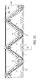
- FIG. 1A is a perspective view of a marine barrier usable in embodiments of the disclosed marine barrier gate.
- FIGS. 1B and 1C are top views of the barrier of FIG. 1A .
- FIGS. 2A-C are views of buoyant panels usable in embodiments of the disclosed marine barrier gate.
- FIGS. 3A-C are views of an outboard hinge usable in embodiments of the disclosed marine barrier gate.
- FIGS. 4A and 4E are perspective views of a barrier usable in embodiments of the disclosed marine barrier gate.
- FIGS. 4B and 4D are top views of the barrier of FIG. 4A .
- FIG. 4C is an end view of the barrier of FIG. 4A .
- FIG. 5 depicts an inboard hinge usable in embodiments of the disclosed marine barrier gate.
- FIG. 6 illustrates a marine barrier gate according to an embodiment of the present disclosure.
- FIGS. 7A-I illustrate a marine barrier gate according to an embodiment of the present disclosure, and its operation.
- FIGS. 8A-F illustrate a marine barrier gate according to another embodiment of the present disclosure, and its operation.
- the disclosed apparatus allows a floating marine structure(s), such as a marine barrier gate, to be moved along a cable system where environmental loads of wind, waves, and currents are borne by a catenary cable, and the operational loads of opening and closing the gate are handled by separate tow cables.
- the apparatus is ideal for repeatedly moving floating gates into open or closed positions. It allows vessels to pass over submerged parts of the system when the floating structures have been moved out of the way using the disclosed apparatus. Generally, the movement of the apparatus is aligned with the longitudinal axis of the floating gate being moved.
- An important advantage of the disclosed apparatus is that it enables the separation of environmental loads of wind, waves and currents from operational loads of moving marine structures from point to point, significantly easing the operational task of moving marine gates and barriers between mooring buoys or fixed structures.
- the disclosed apparatus maintains a continuous connection between the marine structures and the components of the apparatus (e.g., cables) along which the structures travel. This enables safer, simpler automation and remote control, as the marine structures are never released from the apparatus, and the movement of the marine structures always follows a cable, therefore approaching end positions consistently via a controlled path.
- the components of the apparatus e.g., cables
- a marine barrier 100 comprises a first plurality of substantially vertical panels 110 assembled to form a zig-zag shaped (i.e., pleated) barrier, each of the panels 110 having a pair of opposing sides 110 R and 110 L.
- each of the panels 110 includes a frame 111 comprising metal and having a plurality of through holes 112 extending from one major surface to another major surface for allowing passage of water and wind through the panel, a plastic coating 113 encapsulating the frame 111 , and an integral buoyancy portion 114 at the bottom of the frame 111 .
- a panel 110 a includes a buoyancy portion 114 a that is a separate structure attached to a plastic-coated frame 111 a.
- a plurality of hinges 120 each elastically connect an outboard side of a first one of the panels 110 to a side of an adjacent second one of the panels 110 with an included angle A therebetween, to form a buoyant continuous first pleated row of panels 101 , such that the outboard hinges 120 are arranged in first and second substantially parallel rows.
- a plurality of impact cables 130 are attached to opposing ends of the first pleated row of panels 101 and pass through each of the hinges 120 in the first row of hinges.
- there are five impact cables 130 and they are substantially parallel to each other.
- Impact cables 130 comprise, for example, conventional steel wire rope, fiber rope, or synthetic rope. The diameter of impact cables 130 is determined in a conventional manner based on the desired capacity of the system.
- FIG. 1C when the barrier 100 is floating in a body of water 140 and a moving vessel, represented by arrow 150 , impacts one or more of the impact cables 130 , the impact cables 130 deflect to transfer a force of the impact to one or more of the first plurality of panels 110 , which in turn engage the water 140 to transfer the force of the impact to the water 140 , to arrest the motion of the vessel.
- the load path of the impact force of the moving vessel is shown in FIG. 1 c by lines X, Y, and Z, representing the impact force as it moves from the impact cables 130 (line X) to the panels 110 (line Y) and the hinges 120 (lines X and Z).
- outboard hinges 120 each comprise a core 120 a of an elastic material for attaching to the side of the first one of the panels 110 and to the side of the second one of the panels 110 , with the included angle A therebetween, the core 120 a having a passageway 120 b for the impact cables 130 .
- An outer shell 120 c is provided for attaching to and covering a portion of the core 120 a proximal the passageway 120 b , and for engaging the first and second ones of the panels 110 , such that when the barrier 100 is floating in the body of water and a vessel impacts the outer shell 120 c of one of the outboard hinges 120 , the outer shell 120 c guides the vessel into engagement with the impact cables 130 .
- the core 120 a comprises EPDM rubber having a Durometer value of about 60 to about 70
- the outer shell 120 c comprises high density polyethylene.
- hinges 120 enable the panels 110 to move from an expanded position where adjacent ones of the panels 110 are disposed with the included angle A therebetween, to a retracted position where the panels 110 are substantially parallel to each other.
- a tow cable 160 a is attached to an end hinge of one of the rows of hinges 120 and passes through the other hinges 120 of that row of hinges, for moving the panels 110 from the expanded position to the retracted position, as will be described in greater detail herein below.
- a catenary cable 160 b also passes through the hinges 120 of that row of hinges, as will also be described in greater detail herein below. Since the disclosed barrier is retractable, it can be used as a gate; for example, to allow vessels to pass into and out of an area protected by the barrier.
- a marine barrier 400 includes two continuous pleated rows 401 , 402 of first and second respective pluralities of the panels 110 , to form a diamond-shaped barrier.
- a plurality of the outboard hinges 120 , and a plurality of inboard hinges 420 (which will be further described herein below) elastically connect opposing sides of adjacent panels 110 with the included angle A therebetween to form the continuous pleated rows 401 , 402 , such that the hinges 120 , 420 are arranged in first, second, and third substantially parallel rows 410 a - c .
- End hinges 421 a - b also elastic, are similar in structure to inboard hinges 420 , but join only two panels 110 .
- a first plurality of impact cables 430 are attached to opposing ends of the first pleated row of panels 401 and pass through each of the hinges 120 in the first row of hinges 410 a .
- a second plurality of impact cables 430 are attached to opposing ends of the second pleated row of panels 402 and pass through each of the hinges 120 in the third row of hinges 410 c .
- Impact cables 430 comprise, for example, steel wire rope.
- FIGS. 4D-E when the barrier 400 is floating in a body of water 440 and a moving vessel (represented by arrow 450 ) impacts one or more of the first plurality of impact cables 430 attached to the first pleated row 401 of panels 110 , the impact cables 430 deflect to transfer a force of the impact to one or more of the first plurality of panels 110 of the first pleated row 401 , which in turn engage the water 440 , and to one or more of the second plurality of panels of the second pleated row 402 , which in turn engage the water 440 , to transfer the force of the impact to the water 440 and arrest the motion of the vessel.
- the load path of the impact force of the moving vessel is shown in FIGS. 4D-E by lines L, M, and N, representing the impact force as it moves from the impact cables 130 (lines L) to the panels 110 (lines M) and the hinges 120 and 420 (lines L and N).
- the load path of the impact force will be similar, but in an opposite direction to lines L, M, N. shown in FIGS. 4D-E .
- the panels 110 are drawn in around the point of impact and engage the water to dissipate the impact force.
- Each inboard hinge 420 is for joining four panels 110 together, and includes a vertical metal column 420 a and a plurality of ligaments 420 b , 420 c attached to the column 420 a , as by bolts.
- Each ligament 420 b , 420 c is for attaching to a side of each of four of the panels 110 .
- column 420 a is a 5086 aluminum column with a marine coating (more specifically, a 12-inch or 6-inch Schedule 40 pipe).
- Ligaments 420 b , 420 c comprise EDPM rubber.
- the top ligament 420 b has a whip 420 d for engaging one or more of the impact cables 430 between two of the outboard hinges 120 of a row 410 a, c of outboard hinges 120 to support the impact cable(s).
- Whips 420 d perform cable management functions such as keeping cables 430 out of the water when the barrier is being assembled or is in its retracted position, and put a slight tension on cables 430 to prevent sagging and tangling.
- End hinges 421 a - b are of the same construction as inboard hinges 420 , but their ligaments are for attaching to a side of each of only two panels 110 (see FIGS. 4A and 4B ).
- inboard hinges 420 are elastic to enable the panels 110 to move from an expanded position where adjacent ones of the panels 110 are disposed with the included angle A therebetween, to a retracted position where the panels 110 are substantially parallel to each other.
- One or more cables 460 pass through the hinges of the row of inboard hinges 420 , acting as either catenary or tow cable(s) for moving the panels 110 from the expanded position to the retracted position and vice versa, as explained in detail herein below.
- the barrier 400 using the panels 110 of FIG. 2A is about 30 meters long in the expanded position shown in FIG. 4A , with a height of about 2.4 meters, a beam of 4.7 meters, and a draft of 0.35 meters; barrier 400 weighs about 7700 Kg.
- a marine barrier gate 600 includes a pier mount 610 and a stationary transition buoy 620 , between which is attached a barrier 400 a of the type shown in FIGS. 4A-E as barrier 400 .
- Barrier 400 a is attached to pier mount 610 and transition buoy 620 by its end hinges 421 , and is “static” insofar as it normally remains attached to pier mount 610 and buoy 620 .
- another marine barrier 400 b of the type shown as reference numeral 400 extends between a stationary end buoy 630 and a stationary gate buoy 640 and is statically attached to buoys 630 , 640 by its end hinges 421 .
- Buoys 620 and 640 also called “automation buoys,” are for performing several tasks related to opening and closing marine barrier gate 600 , typically by remote control. They include conventional equipment such as winches, power systems, hydraulics, latches, and a berth for a remote operated vehicle (ROV), as necessary. This equipment will be described in detail herein below.
- ROV remote operated vehicle
- a movable barrier 400 c (also of the type shown as reference numeral 400 ) extends between transition buoy 620 and gate buoy 640 .
- Barrier 400 c is attached by one of its end hinges 421 to transition buoy 620 , and is expandable and retractable between buoys 620 and 640 by a methodology and apparatus that will now be described with reference to FIGS. 7A-7I .
- the disclosed marine barrier gate 700 comprises a substantially stationary first buoy, such as transition buoy 620 , attached to a first end hinge 421 a of the second row of hinges 410 b (as best seen in FIG. 4B ) of a barrier 400 such as barrier 400 c of FIG. 6 .
- a substantially stationary second buoy such as gate buoy 640
- the second buoy 640 having a first tow winch 640 a with a first tow cable 460 a extendible to, and attachable to, a second end hinge 421 b of the second row of hinges 410 b opposite the first end hinge 421 a , for moving the panels 110 from the retracted position shown in FIG. 7A to the expanded position shown in FIG. 7G by operation of the first tow winch 640 a .
- the free end of the first tow cable 460 a has a float 710 .
- the first buoy 620 comprises a catenary winch 620 a with a catenary cable 460 b that passes through the hinges 420 of the second row of hinges 410 b (see, e.g., cables 460 of FIGS. 4B and 4D ) so it is movably engagable with the first and second pleated rows of panels 401 , 402 and extendible and attachable to the second buoy 640 .
- the free end of the catenary cable 460 b has a float 720 .
- winches described herein mounted to buoys 620 , 640 are readily-available conventional winches known to those of skill in the art, and are remotely operated in a well-known manner, to eliminate the need for human labor, thereby reducing costs and danger to personnel.
- the marine barrier gate further comprises a remote operated vehicle (ROV) 730 for capturing the float 710 and transporting the free end of the first tow cable 460 a from the second buoy 640 to the barrier 400 c for attachment to its second end hinge 421 b , and for capturing the float 720 and transporting the free end of the catenary cable 460 b to the second buoy 640 for attachment to the second buoy 640 , when the barrier 400 c is in the retracted position.
- ROV 730 is a conventional ROV, such as the “Small Unmanned Surface Vehicle” or the “E.M.I.L.Y.” available from Hydranalix of Green Valley, Ariz.
- ROV 730 is controlled from a command and control center with pre-set commands, or is controlled by a portable command box, in a conventional manner.
- Use of an ROV 730 is advantageous because operating personnel are not vulnerable to attack, ROV 730 is not a hazard to navigation, and ROV's have been proven to perform well in rough environments at low cost.
- a manually-operated tow boat is used instead of ROV 730 to expand the barrier and transport the catenary cable 460 b.
- FIG. 7A shows barrier 400 c in the retracted position and the ROV 730 docked at the second buoy 640 .
- the gate is ready to be expanded.
- the ROV 730 undocks and captures the float 710 of the first tow cable 460 a , spans the gate opening by moving in the direction of the arrow S towards first buoy 620 (as shown by the dashed lines) and connects the first tow cable 460 a to the second end hinge 421 b of barrier 400 c .
- FIG. 7B shows barrier 400 c in the retracted position and the ROV 730 docked at the second buoy 640 .
- the ROV 730 undocks and captures the float 710 of the first tow cable 460 a , spans the gate opening by moving in the direction of the arrow S towards first buoy 620 (as shown by the dashed lines) and connects the first tow cable 460 a to the second end hinge 421 b of barrier 400 c .
- the ROV 730 captures the float 720 of the catenary cable 460 b , spans the gate opening by moving in the direction of the arrow T towards second buoy 640 , and connects the catenary cable 460 b to second buoy 640 as shown in FIG. 7D .
- Catenary cable 460 b is connected to second buoy 640 in a conventional manner, such as by locking into a set of hydraulic jaws 640 b on second buoy 640 that act as a latch for catenary cable 460 b .
- the ROV 730 then redocks.
- the catenary cable 460 b is thereafter reeled in to catenary winch 620 a to a desired tension or length, so it will absorb catenary loads on the barrier 400 c when the panels 110 are moved from the retracted position to the expanded position.
- the first tow cable 460 a is then reeled in to first tow winch 640 a to pull the barrier 400 c across the gate span (see FIG. 7F ).
- the second buoy 640 comprises a latch 640 c for engaging the second end hinge 421 b to retain the barrier 400 c in the expanded position.
- FIG. 7G shows the barrier 400 c fully expanded, and the marine barrier gate 700 thereby closed.
- the first buoy 620 has a second tow winch 620 b with a second tow cable 740 , which passes through the hinges 420 of the second row of hinges 410 b and is attached to the second end hinge 421 b , for moving the panels 110 from the expanded position shown in FIG. 7G to the retracted position of FIG. 7I by operation of the second tow winch 620 b.
- the latch 640 c of the second buoy 640 is disengaged from the second end hinge 421 b of barrier 400 c , and the first tow cable 460 a is detached from the second end hinge 421 b .
- the catenary cable 460 b remains attached to the second buoy 640 .
- the second tow cable 740 is then reeled in to the second tow winch 620 b (see FIG.
- the latch 640 b releases the free end of the catenary cable 460 b , and the catenary winch 620 a reels in the catenary cable 460 b .
- the gate 700 is now open, and vessels can pass between the buoys 620 , 640 . Further, the gate 700 is reset and ready to be closed again when necessary.
- the marine barrier gate 800 of this embodiment is identical to that of the gate 700 of FIGS. 7A-I , except that the first tow cable and the catenary cable are respectively permanently attached to the barrier 400 c and the second buoy 640 , and are long enough to be submersible.
- the gate 800 When the gate 800 is open these cables sit on the sea floor, and when the gate is to be closed the cables rise and come under tension (by operation of their respective winches) to expand and close the gate without an ROV or a manned tow boat.
- the barrier 400 c is pulled along the catenary cable, and when the gate is fully retracted, the cable tension is released by the winches and the two cables drop to the seafloor under their own weight, allowing unhindered vessel passage through the gate and over the submerged cables.
- a submersible tow cable 810 is fixedly attached to the second end hinge 421 b of the second row of hinges 410 b of barrier 400 c , and is extendible by the first tow winch 640 a to a position below a surface 820 a of body of water 820 when the panels 110 of barrier 400 c are in the retracted position; i.e., when the gate 800 is open.
- a submersible catenary cable 830 is fixedly attached to the second buoy 640 at attachment point 640 d , and is extendible by the catenary winch 620 a to a position below the surface 820 a of the body of water 820 when the panels 110 of barrier 400 c are in the retracted position.
- vessels can pass unhindered through the gate 800 .
- FIGS. 8B-C when the gate 800 is to be closed the submersible catenary cable 830 is reeled in by catenary winch 620 a to a desired tension or length, so it will absorb catenary loads on the barrier 400 c when the panels 110 are moved from the retracted position to the expanded position.
- the submersible tow cable 810 is then reeled in by first tow winch 640 a to pull the barrier 400 c across the gate span in the direction of arrow P (see FIG. 8C ).
- the latch 640 c of the second buoy 640 engages the second end hinge 421 b to retain the barrier 400 c in the expanded position.
- FIG. 8D shows the barrier 400 c fully expanded, and the marine barrier gate 800 thereby closed.
- the latch 640 c of the second buoy 640 is disengaged from the second end hinge 421 b of barrier 400 c .
- the second tow cable 740 is then reeled onto the second tow winch 620 b (see FIG. 8E ), while the first tow winch 640 a extends the submersible tow cable 810 to allow the second tow cable 740 to move the panels 110 from the expanded position to the retracted position in the direction of arrow Q.
- the catenary winch 620 a maintains a length or tension of the submersible catenary cable 830 such that the submersible catenary cable 830 absorbs catenary loads on the barrier 400 c when the panels 110 are moved from the expanded position to the retracted position by operation of the second tow winch 620 b.
- the first tow winch 640 a further reels out submersible tow cable 810 , which sinks under the surface 820 a of the water 820 ; for example, to the sea floor.
- the catenary winch 620 a reels out submersible catenary cable 830 , which sinks under the surface 820 a under its own weight.
- the gate 800 is now open, as shown in FIG. 8F , and vessels can pass between the buoys 620 , 640 . Further, the gate 800 is reset and ready to be closed again when necessary.
Abstract
Description
Claims (22)
Priority Applications (3)
| Application Number | Priority Date | Filing Date | Title |
|---|---|---|---|
| US13/598,353 US8739725B2 (en) | 2011-09-01 | 2012-08-29 | Marine barrier gate |
| US14/261,242 US9121153B2 (en) | 2011-09-01 | 2014-04-24 | Marine barrier gate |
| US14/836,825 US20150361631A1 (en) | 2011-09-01 | 2015-08-26 | Marine barrier gate |
Applications Claiming Priority (3)
| Application Number | Priority Date | Filing Date | Title |
|---|---|---|---|
| US201161573099P | 2011-09-01 | 2011-09-01 | |
| US201161628620P | 2011-11-03 | 2011-11-03 | |
| US13/598,353 US8739725B2 (en) | 2011-09-01 | 2012-08-29 | Marine barrier gate |
Related Child Applications (1)
| Application Number | Title | Priority Date | Filing Date |
|---|---|---|---|
| US14/261,242 Continuation US9121153B2 (en) | 2011-09-01 | 2014-04-24 | Marine barrier gate |
Publications (2)
| Publication Number | Publication Date |
|---|---|
| US20130108368A1 US20130108368A1 (en) | 2013-05-02 |
| US8739725B2 true US8739725B2 (en) | 2014-06-03 |
Family
ID=47756808
Family Applications (4)
| Application Number | Title | Priority Date | Filing Date |
|---|---|---|---|
| US13/586,270 Active US8920075B2 (en) | 2011-09-01 | 2012-08-15 | Marine barrier and gate |
| US13/598,353 Active 2032-10-23 US8739725B2 (en) | 2011-09-01 | 2012-08-29 | Marine barrier gate |
| US14/261,242 Active US9121153B2 (en) | 2011-09-01 | 2014-04-24 | Marine barrier gate |
| US14/836,825 Abandoned US20150361631A1 (en) | 2011-09-01 | 2015-08-26 | Marine barrier gate |
Family Applications Before (1)
| Application Number | Title | Priority Date | Filing Date |
|---|---|---|---|
| US13/586,270 Active US8920075B2 (en) | 2011-09-01 | 2012-08-15 | Marine barrier and gate |
Family Applications After (2)
| Application Number | Title | Priority Date | Filing Date |
|---|---|---|---|
| US14/261,242 Active US9121153B2 (en) | 2011-09-01 | 2014-04-24 | Marine barrier gate |
| US14/836,825 Abandoned US20150361631A1 (en) | 2011-09-01 | 2015-08-26 | Marine barrier gate |
Country Status (7)
| Country | Link |
|---|---|
| US (4) | US8920075B2 (en) |
| EP (1) | EP2751516B8 (en) |
| CN (1) | CN103906988B (en) |
| ES (1) | ES2593271T3 (en) |
| IL (1) | IL231194A (en) |
| MY (1) | MY182235A (en) |
| WO (2) | WO2013033091A1 (en) |
Cited By (2)
| Publication number | Priority date | Publication date | Assignee | Title |
|---|---|---|---|---|
| US9863109B2 (en) * | 2015-03-30 | 2018-01-09 | Halo Maritime Defense Systems, Inc. | Cable management for marine barriers and gate systems |
| US10861270B2 (en) | 2018-02-01 | 2020-12-08 | Halo Maritime Defense Systems, Inc. | Presence-based automatic gate operation for marine barriers and gate systems |
Families Citing this family (26)
| Publication number | Priority date | Publication date | Assignee | Title |
|---|---|---|---|---|
| NO332748B1 (en) * | 2010-04-20 | 2013-01-02 | Rygg Consulting | oil boom |
| US8920075B2 (en) * | 2011-09-01 | 2014-12-30 | Halo Maritime Defense Systems, Inc. | Marine barrier and gate |
| US9493855B2 (en) | 2013-02-22 | 2016-11-15 | The Nanosteel Company, Inc. | Class of warm forming advanced high strength steel |
| EP3074715A4 (en) * | 2013-11-26 | 2017-06-21 | Halo Maritime Defense Systems, Inc. | Energy absorption management for marine barrier and gate systems |
| NZ726513A (en) | 2014-05-28 | 2023-07-28 | Memorial Sloan Kettering Cancer Center | Anti-gitr antibodies and methods of use thereof |
| US9677243B2 (en) * | 2014-09-08 | 2017-06-13 | Robert G. Carroll, JR. | Corrugated retention and filtration systems for sedimentation control |
| HUE050750T2 (en) | 2015-05-29 | 2021-01-28 | Agenus Inc | Anti-ctla-4 antibodies and methods of use thereof |
| KR102366813B1 (en) | 2016-05-27 | 2022-02-24 | 아게누스 인코포레이티드 | Anti-TIM-3 Antibodies and Methods of Using Same |
| CN106012949B (en) * | 2016-07-05 | 2018-09-14 | 中山市祥实水利建筑工程有限公司 | Seasonal key water control project |
| IL265800B2 (en) | 2016-10-11 | 2023-10-01 | Agenus Inc | Anti-lag-3 antibodies and methods of use thereof |
| EP3538152A4 (en) | 2016-11-09 | 2020-09-30 | Agenus Inc. | Anti-ox40 antibodies, anti-gitr antibodies, and methods of use thereof |
| MA50949B1 (en) | 2016-12-07 | 2023-12-29 | Memorial Sloan Kettering Cancer Center | ANTI-CTLA-4 ANTIBODIES AND METHODS OF USE THEREOF |
| KR102603681B1 (en) | 2016-12-07 | 2023-11-17 | 아게누스 인코포레이티드 | Antibodies and methods of using them |
| EP3568412A2 (en) | 2017-01-13 | 2019-11-20 | Agenus Inc. | T cell receptors that bind to ny-eso-1 and methods of use thereof |
| WO2018170072A1 (en) | 2017-03-15 | 2018-09-20 | Halo Maritime Defense Systems, Inc. | Automatic gate operation and system status indication for marine barriers and gate systems |
| TW201841942A (en) | 2017-04-13 | 2018-12-01 | 美商艾吉納斯公司 | Anti-CD137 antibodies and methods of use thereof |
| MA50957A (en) | 2017-05-01 | 2020-10-14 | Agenus Inc | ANTI-TIGIT ANTIBODIES AND THEIR METHODS OF USE |
| US10145659B1 (en) * | 2017-08-25 | 2018-12-04 | Halo Maritime Defense Systems, Inc. | Rapidly deployable single net capture marine barrier system |
| AU2018326875A1 (en) | 2017-09-04 | 2020-03-19 | Agenus Inc. | T cell receptors that bind to mixed lineage leukemia (MLL)-specific phosphopeptides and methods of use thereof |
| CN108387144A (en) * | 2018-02-01 | 2018-08-10 | 大工科创船海工程研究院(大连)有限公司 | A kind of Double-protection wall arresting gear waterborne based on articulated stand support |
| CN108387145A (en) * | 2018-02-01 | 2018-08-10 | 大工科创船海工程研究院(大连)有限公司 | A kind of Double-protection wall arresting gear waterborne based on spring buffer |
| US11879222B2 (en) * | 2018-04-12 | 2024-01-23 | Woosb Ltd | Oil spill barrier |
| MA52363A (en) | 2018-04-26 | 2021-03-03 | Agenus Inc | THERMAL SHOCK PROTEIN (HSP) PEPTIDIC COMPOSITIONS AND THEIR METHODS OF USE |
| WO2021042019A1 (en) | 2019-08-30 | 2021-03-04 | Agenus Inc. | Anti-cd96 antibodies and methods of use thereof |
| WO2021257860A1 (en) | 2020-06-19 | 2021-12-23 | Halo Maritime Defense Systems, Inc. | Compliant single net marine barrier |
| US11608656B2 (en) | 2021-02-17 | 2023-03-21 | Joshua Peter Harold Jordan | Portable removable barrier |
Citations (42)
| Publication number | Priority date | Publication date | Assignee | Title |
|---|---|---|---|---|
| US2693161A (en) | 1952-06-18 | 1954-11-02 | Sherman C Stubbs | Buoyant seaweed collecting fence |
| US3499291A (en) | 1967-11-06 | 1970-03-10 | Trygve Mikkelsen | Boom for screening in and collecting up of pollution on water |
| US3604389A (en) | 1969-01-27 | 1971-09-14 | Cable Ferry Systems | Water transportation system with shore-based propulsion |
| US3823680A (en) | 1971-07-19 | 1974-07-16 | O Straumsnes | Underseas transport system |
| US3864049A (en) | 1973-01-11 | 1975-02-04 | Taisaburo Ono | Construction elements of underwater trusses |
| US4033137A (en) | 1973-07-12 | 1977-07-05 | Geist James J | Articulated floating barrier |
| US4174185A (en) | 1977-11-14 | 1979-11-13 | Mitsubishi Jukogyo Kabushiki Kaisha | Floating-type anti-oil anti-impact and anti-wave barrier |
| US4272214A (en) | 1978-11-06 | 1981-06-09 | Harry Nyfeldt | Floating fence for the collection of liquid impurities as for example oil on a water surface |
| US4319858A (en) | 1978-10-16 | 1982-03-16 | Societe Anonyme Rolba | High resistance flexible boom |
| US4425053A (en) | 1978-08-09 | 1984-01-10 | Mitsui Ocean Development & Engineering Co., Ltd. | Oil fence arrangement |
| US4681302A (en) * | 1983-12-02 | 1987-07-21 | Thompson Marion L | Energy absorbing barrier |
| US5062739A (en) * | 1982-09-25 | 1991-11-05 | Albrecht Klockner | Zigzag breakwater |
| US5141359A (en) | 1991-08-19 | 1992-08-25 | Albrecht Klockner | Zigzag breakwater |
| US5429452A (en) | 1993-08-24 | 1995-07-04 | Waterbreak, Inc. | Floating break water structure |
| US5651709A (en) | 1995-11-09 | 1997-07-29 | Nortrans Engineering Group Pte Ltd. | Cantenary anchor leg mooring buoy |
| US5827011A (en) | 1996-12-23 | 1998-10-27 | Kann; Dirk C. | Wave suppression system |
| US6102616A (en) | 1999-04-09 | 2000-08-15 | Foote; Howard G. | Wave break |
| US6591774B2 (en) | 2001-05-24 | 2003-07-15 | Mark B. Metherell | Apparatus and method for protecting ships and harbors from attack by vessels |
| US20030190191A1 (en) | 2002-04-06 | 2003-10-09 | Wave Control Systems Inc. | Wave attenuator |
| US6655641B2 (en) | 1999-12-14 | 2003-12-02 | Yury Sherman | System for supporting substantially rigid linear structures |
| US20040018060A1 (en) | 2002-08-02 | 2004-01-29 | Ita Industrial | Protection barrier apparatus |
| US20040115002A1 (en) | 2002-11-19 | 2004-06-17 | Meeks Paul S. | Boat Barrier Attachment for Log and Debris Booms |
| US6843197B1 (en) | 2003-07-17 | 2005-01-18 | The United States Of America As Represented By The Secretary Of The Navy | Near shore port security barrier |
| US6860209B2 (en) | 1996-06-11 | 2005-03-01 | Mckoy Errol W. | Watercraft amusement ride |
| US6877455B2 (en) | 2001-05-17 | 2005-04-12 | Kwang Sun Hong | Prefabricated boat |
| US6886484B2 (en) | 2003-02-12 | 2005-05-03 | Georg K. Thomas | Composite tension rod terminal systems |
| US20050191129A1 (en) * | 2002-04-02 | 2005-09-01 | Yodock Leo J.Iii | Floating barrier units |
| US6980483B2 (en) | 2003-02-12 | 2005-12-27 | Science Applications International Corporation | Harbor fence |
| US7140599B1 (en) | 2002-12-31 | 2006-11-28 | Richard Spink | Coupling systems and methods for marine barriers |
| US20080105184A1 (en) | 2006-11-06 | 2008-05-08 | Laurence Nixon | Port security barrier |
| US20080267717A1 (en) * | 2007-04-30 | 2008-10-30 | Kepner Plastics Fabricators, Inc. | Floating standoff assembly |
| US20080279631A1 (en) | 2003-12-11 | 2008-11-13 | Justin Bishop | Wave attenuator and security barrier system - connector |
| US7451527B2 (en) | 2003-06-14 | 2008-11-18 | Colt Systems Limited | Rope terminator |
| US7481176B2 (en) | 2006-06-05 | 2009-01-27 | United States Of America As Represented By The Secretary Of The Army | Transportable flotation system |
| US20090035068A1 (en) | 2007-08-02 | 2009-02-05 | Terai Jeffrey B | Fixed Security Barrier |
| US20090090059A1 (en) | 2006-07-14 | 2009-04-09 | Justin Bishop | System and method of using rope in security application |
| US7572083B1 (en) | 2000-09-26 | 2009-08-11 | Elemental Innovation Inc. | Floating breakwater system and method for dissipating wave energy |
| US20100059728A1 (en) | 2006-07-14 | 2010-03-11 | Justin Bishop | Security barrier |
| US7726910B2 (en) | 2004-09-15 | 2010-06-01 | Offshore Technology Development Pte Ltd. | Interactive leg guide for offshore self-elevating unit |
| US20100239374A1 (en) * | 2006-08-02 | 2010-09-23 | Davis Gregory A | Protective marine barrier system |
| US7975639B2 (en) | 2006-07-14 | 2011-07-12 | Halo Maritime Defense Systems, Inc. | Float for use in water-based security system |
| US20130119334A1 (en) * | 2011-09-01 | 2013-05-16 | Justin Bishop | Marine barrier and gate |
Family Cites Families (5)
| Publication number | Priority date | Publication date | Assignee | Title |
|---|---|---|---|---|
| US4484836A (en) * | 1982-07-26 | 1984-11-27 | Bailard James A | Pneumatic spar sediment control curtain |
| US20050058509A1 (en) | 2003-09-15 | 2005-03-17 | Dov Steinberg | Floating modular breakwater |
| WO2008144534A1 (en) * | 2007-05-17 | 2008-11-27 | David Lee Glessner | Marine vessel landing site barrier |
| US20100178109A1 (en) | 2009-01-09 | 2010-07-15 | Dave David Matthew Wilson | Self-adjusting wave break |
| NO336028B1 (en) * | 2009-07-06 | 2015-04-20 | Cruise Ventures As | Floating walkway for transporting persons and goods between a ship and a land area, methods for connecting the walkway to and from a ship, and uses thereof |
-
2012
- 2012-08-15 US US13/586,270 patent/US8920075B2/en active Active
- 2012-08-28 WO PCT/US2012/052655 patent/WO2013033091A1/en active Application Filing
- 2012-08-29 US US13/598,353 patent/US8739725B2/en active Active
- 2012-08-30 WO PCT/US2012/053094 patent/WO2013033364A1/en active Application Filing
- 2012-08-30 EP EP12827576.5A patent/EP2751516B8/en not_active Not-in-force
- 2012-08-30 MY MYPI2014000568A patent/MY182235A/en unknown
- 2012-08-30 CN CN201280053422.4A patent/CN103906988B/en not_active Expired - Fee Related
- 2012-08-30 ES ES12827576.5T patent/ES2593271T3/en active Active
-
2014
- 2014-02-27 IL IL231194A patent/IL231194A/en active IP Right Grant
- 2014-04-24 US US14/261,242 patent/US9121153B2/en active Active
-
2015
- 2015-08-26 US US14/836,825 patent/US20150361631A1/en not_active Abandoned
Patent Citations (53)
| Publication number | Priority date | Publication date | Assignee | Title |
|---|---|---|---|---|
| US2693161A (en) | 1952-06-18 | 1954-11-02 | Sherman C Stubbs | Buoyant seaweed collecting fence |
| US3499291A (en) | 1967-11-06 | 1970-03-10 | Trygve Mikkelsen | Boom for screening in and collecting up of pollution on water |
| US3604389A (en) | 1969-01-27 | 1971-09-14 | Cable Ferry Systems | Water transportation system with shore-based propulsion |
| US3823680A (en) | 1971-07-19 | 1974-07-16 | O Straumsnes | Underseas transport system |
| US3864049A (en) | 1973-01-11 | 1975-02-04 | Taisaburo Ono | Construction elements of underwater trusses |
| US4033137A (en) | 1973-07-12 | 1977-07-05 | Geist James J | Articulated floating barrier |
| US4174185A (en) | 1977-11-14 | 1979-11-13 | Mitsubishi Jukogyo Kabushiki Kaisha | Floating-type anti-oil anti-impact and anti-wave barrier |
| US4425053A (en) | 1978-08-09 | 1984-01-10 | Mitsui Ocean Development & Engineering Co., Ltd. | Oil fence arrangement |
| US4319858A (en) | 1978-10-16 | 1982-03-16 | Societe Anonyme Rolba | High resistance flexible boom |
| US4272214A (en) | 1978-11-06 | 1981-06-09 | Harry Nyfeldt | Floating fence for the collection of liquid impurities as for example oil on a water surface |
| US5062739A (en) * | 1982-09-25 | 1991-11-05 | Albrecht Klockner | Zigzag breakwater |
| US4681302A (en) * | 1983-12-02 | 1987-07-21 | Thompson Marion L | Energy absorbing barrier |
| US5141359A (en) | 1991-08-19 | 1992-08-25 | Albrecht Klockner | Zigzag breakwater |
| US5429452A (en) | 1993-08-24 | 1995-07-04 | Waterbreak, Inc. | Floating break water structure |
| US5651709A (en) | 1995-11-09 | 1997-07-29 | Nortrans Engineering Group Pte Ltd. | Cantenary anchor leg mooring buoy |
| US6860209B2 (en) | 1996-06-11 | 2005-03-01 | Mckoy Errol W. | Watercraft amusement ride |
| US5827011A (en) | 1996-12-23 | 1998-10-27 | Kann; Dirk C. | Wave suppression system |
| US6102616A (en) | 1999-04-09 | 2000-08-15 | Foote; Howard G. | Wave break |
| US6655641B2 (en) | 1999-12-14 | 2003-12-02 | Yury Sherman | System for supporting substantially rigid linear structures |
| US7572083B1 (en) | 2000-09-26 | 2009-08-11 | Elemental Innovation Inc. | Floating breakwater system and method for dissipating wave energy |
| US6877455B2 (en) | 2001-05-17 | 2005-04-12 | Kwang Sun Hong | Prefabricated boat |
| US6591774B2 (en) | 2001-05-24 | 2003-07-15 | Mark B. Metherell | Apparatus and method for protecting ships and harbors from attack by vessels |
| US20050191129A1 (en) * | 2002-04-02 | 2005-09-01 | Yodock Leo J.Iii | Floating barrier units |
| US20040018055A1 (en) * | 2002-04-06 | 2004-01-29 | Wave Control Systems, Inc. | Wave attenuator |
| US20030190191A1 (en) | 2002-04-06 | 2003-10-09 | Wave Control Systems Inc. | Wave attenuator |
| US20040018060A1 (en) | 2002-08-02 | 2004-01-29 | Ita Industrial | Protection barrier apparatus |
| US20060037526A1 (en) | 2002-08-02 | 2006-02-23 | Innovative Technology Application, Inc. | Pontoon for protection barrier system |
| US6960047B2 (en) | 2002-08-02 | 2005-11-01 | Innovative Technology Application, Inc. | Protection barrier apparatus |
| US20060034668A1 (en) | 2002-08-02 | 2006-02-16 | Innovative Technology Application, Inc. | Winch gate for protection barrier system |
| US20040115002A1 (en) | 2002-11-19 | 2004-06-17 | Meeks Paul S. | Boat Barrier Attachment for Log and Debris Booms |
| US7140599B1 (en) | 2002-12-31 | 2006-11-28 | Richard Spink | Coupling systems and methods for marine barriers |
| US6886484B2 (en) | 2003-02-12 | 2005-05-03 | Georg K. Thomas | Composite tension rod terminal systems |
| US6980483B2 (en) | 2003-02-12 | 2005-12-27 | Science Applications International Corporation | Harbor fence |
| US7451527B2 (en) | 2003-06-14 | 2008-11-18 | Colt Systems Limited | Rope terminator |
| US20050013668A1 (en) | 2003-07-17 | 2005-01-20 | Nixon Laurence G. | Near shore port security barrier |
| US6843197B1 (en) | 2003-07-17 | 2005-01-18 | The United States Of America As Represented By The Secretary Of The Navy | Near shore port security barrier |
| US7524139B2 (en) | 2003-12-11 | 2009-04-28 | Elemental Innovation, Inc. | Wave attenuator and security barrier system—connector |
| US7524140B2 (en) | 2003-12-11 | 2009-04-28 | Elemental Innovation, Inc. | Wave attenuator and security barrier system—adjusting |
| US7887254B2 (en) | 2003-12-11 | 2011-02-15 | Halo Maritime Defense Systems, Inc. | Wave attenuator and security barrier system-adjustor |
| US20080279631A1 (en) | 2003-12-11 | 2008-11-13 | Justin Bishop | Wave attenuator and security barrier system - connector |
| US7726910B2 (en) | 2004-09-15 | 2010-06-01 | Offshore Technology Development Pte Ltd. | Interactive leg guide for offshore self-elevating unit |
| US7481176B2 (en) | 2006-06-05 | 2009-01-27 | United States Of America As Represented By The Secretary Of The Army | Transportable flotation system |
| US20100059728A1 (en) | 2006-07-14 | 2010-03-11 | Justin Bishop | Security barrier |
| US20090090059A1 (en) | 2006-07-14 | 2009-04-09 | Justin Bishop | System and method of using rope in security application |
| US7975639B2 (en) | 2006-07-14 | 2011-07-12 | Halo Maritime Defense Systems, Inc. | Float for use in water-based security system |
| US8020836B2 (en) | 2006-07-14 | 2011-09-20 | Halo Maritime Defense Systems, Inc. | Security barrier |
| US20100239374A1 (en) * | 2006-08-02 | 2010-09-23 | Davis Gregory A | Protective marine barrier system |
| US8007202B2 (en) | 2006-08-02 | 2011-08-30 | Honeywell International, Inc. | Protective marine barrier system |
| US7401565B2 (en) | 2006-11-06 | 2008-07-22 | United States Of America As Represented By The Secretary Of The Navy | Port security barrier |
| US20080105184A1 (en) | 2006-11-06 | 2008-05-08 | Laurence Nixon | Port security barrier |
| US20080267717A1 (en) * | 2007-04-30 | 2008-10-30 | Kepner Plastics Fabricators, Inc. | Floating standoff assembly |
| US20090035068A1 (en) | 2007-08-02 | 2009-02-05 | Terai Jeffrey B | Fixed Security Barrier |
| US20130119334A1 (en) * | 2011-09-01 | 2013-05-16 | Justin Bishop | Marine barrier and gate |
Non-Patent Citations (2)
| Title |
|---|
| International Search Report and Written Opinion issued in International Patent Application No. PCT/US2012/052655 mailed Nov. 6, 2012. |
| International Search Report and Written Opinion issued in International Patent Application No. PCT/US2012/053094 mailed Nov. 20, 2012. |
Cited By (2)
| Publication number | Priority date | Publication date | Assignee | Title |
|---|---|---|---|---|
| US9863109B2 (en) * | 2015-03-30 | 2018-01-09 | Halo Maritime Defense Systems, Inc. | Cable management for marine barriers and gate systems |
| US10861270B2 (en) | 2018-02-01 | 2020-12-08 | Halo Maritime Defense Systems, Inc. | Presence-based automatic gate operation for marine barriers and gate systems |
Also Published As
| Publication number | Publication date |
|---|---|
| US20130119334A1 (en) | 2013-05-16 |
| MY182235A (en) | 2021-01-18 |
| US9121153B2 (en) | 2015-09-01 |
| CN103906988B (en) | 2016-06-29 |
| US8920075B2 (en) | 2014-12-30 |
| EP2751516B1 (en) | 2016-06-29 |
| WO2013033091A1 (en) | 2013-03-07 |
| ES2593271T3 (en) | 2016-12-07 |
| CN103906988A (en) | 2014-07-02 |
| EP2751516B8 (en) | 2016-09-14 |
| US20150361631A1 (en) | 2015-12-17 |
| IL231194A0 (en) | 2014-04-30 |
| EP2751516A4 (en) | 2015-06-03 |
| US20140231734A1 (en) | 2014-08-21 |
| IL231194A (en) | 2017-10-31 |
| EP2751516A1 (en) | 2014-07-09 |
| WO2013033364A1 (en) | 2013-03-07 |
| US20130108368A1 (en) | 2013-05-02 |
Similar Documents
| Publication | Publication Date | Title |
|---|---|---|
| US8739725B2 (en) | Marine barrier gate | |
| US7401565B2 (en) | Port security barrier | |
| US8801327B2 (en) | Marine ropeway | |
| US7140599B1 (en) | Coupling systems and methods for marine barriers | |
| CA2867001C (en) | Trolley for a weather maintenance system for a wind turbine maintenance program | |
| CN109415106B (en) | Emergency stop system and method | |
| CN112918636B (en) | Sea condition self-adaptive distribution and recovery device for rapidly collecting and releasing unmanned ship | |
| BR112021004988A2 (en) | marine structure comprising a launch and recovery system | |
| US9863109B2 (en) | Cable management for marine barriers and gate systems | |
| CN110877666A (en) | Self-propelled underwater tunnel immersed tube carrying and mounting integrated ship and construction process | |
| JP6406665B2 (en) | Floating fish reef collection device and collection method | |
| US5241920A (en) | Hook assembly for broken tow line retrieval and emergency marine towing | |
| JPH029996B2 (en) | ||
| KR102237126B1 (en) | Quay mooring auxiliary device for ship, and mooring system comprising the same and method thereof | |
| US4246860A (en) | Method for anchor retrieval | |
| KR101152677B1 (en) | Vessel towing apparatus having watertighting part | |
| AU2022231160A1 (en) | Floating barrier system | |
| Shepherd et al. | Observatory cable laying system | |
| CN117485465A (en) | Moon pool system of marine underwater detection equipment | |
| CN117418519A (en) | Quick connecting joint for oil fence, oil fence and shaping and enclosing control method | |
| CN115045246A (en) | Raft type air curtain reinforced mesh fence oil containment boom device suitable for wave current working condition | |
| Irish et al. | TTTTTT | |
| KR20150021304A (en) | Floating power plant mooring apparatus |
Legal Events
| Date | Code | Title | Description |
|---|---|---|---|
| AS | Assignment |
Owner name: HALO MARITIME DEFENSE SYSTEMS, NEW JERSEY Free format text: ASSIGNMENT OF ASSIGNORS INTEREST;ASSIGNOR:BISHOP, JUSTIN;REEL/FRAME:029623/0725 Effective date: 20130107 |
|
| AS | Assignment |
Owner name: KLOTZ, ELIZABETH, NEW YORK Free format text: SECURITY AGREEMENT;ASSIGNOR:HALO MARITIME DEFENSE SYSTEMS, INC.;REEL/FRAME:030295/0617 Effective date: 20130418 Owner name: THE LINDEN TRUST, OHIO Free format text: SECURITY AGREEMENT;ASSIGNOR:HALO MARITIME DEFENSE SYSTEMS, INC.;REEL/FRAME:030295/0617 Effective date: 20130418 Owner name: SARNICOLA, NICK, FLORIDA Free format text: SECURITY AGREEMENT;ASSIGNOR:HALO MARITIME DEFENSE SYSTEMS, INC.;REEL/FRAME:030295/0617 Effective date: 20130418 Owner name: PENINSULA OVERVIEW PARTNERS, LLC, NEW YORK Free format text: SECURITY AGREEMENT;ASSIGNOR:HALO MARITIME DEFENSE SYSTEMS, INC.;REEL/FRAME:030295/0617 Effective date: 20130418 Owner name: HOURIHAN, NEIL A., NEW YORK Free format text: SECURITY AGREEMENT;ASSIGNOR:HALO MARITIME DEFENSE SYSTEMS, INC.;REEL/FRAME:030295/0617 Effective date: 20130418 Owner name: LEWIS, DANIEL, NEW YORK Free format text: SECURITY AGREEMENT;ASSIGNOR:HALO MARITIME DEFENSE SYSTEMS, INC.;REEL/FRAME:030295/0617 Effective date: 20130418 Owner name: JANET CARTER TRUST, CALIFORNIA Free format text: SECURITY AGREEMENT;ASSIGNOR:HALO MARITIME DEFENSE SYSTEMS, INC.;REEL/FRAME:030295/0617 Effective date: 20130418 Owner name: DEFOSSET, DONALD, FLORIDA Free format text: SECURITY AGREEMENT;ASSIGNOR:HALO MARITIME DEFENSE SYSTEMS, INC.;REEL/FRAME:030295/0617 Effective date: 20130418 Owner name: PEIFER, CHRISTOPHER TICE, CONNECTICUT Free format text: SECURITY AGREEMENT;ASSIGNOR:HALO MARITIME DEFENSE SYSTEMS, INC.;REEL/FRAME:030295/0617 Effective date: 20130418 Owner name: CANTER, CHIP, NEW YORK Free format text: SECURITY AGREEMENT;ASSIGNOR:HALO MARITIME DEFENSE SYSTEMS, INC.;REEL/FRAME:030295/0617 Effective date: 20130418 Owner name: IROQUOIS MASTER FUND LTD., NEW YORK Free format text: SECURITY AGREEMENT;ASSIGNOR:HALO MARITIME DEFENSE SYSTEMS, INC.;REEL/FRAME:030295/0617 Effective date: 20130418 Owner name: EMD INVESTORS, CONNECTICUT Free format text: SECURITY AGREEMENT;ASSIGNOR:HALO MARITIME DEFENSE SYSTEMS, INC.;REEL/FRAME:030295/0617 Effective date: 20130418 Owner name: WOLF, JEFFREY, NEW YORK Free format text: SECURITY AGREEMENT;ASSIGNOR:HALO MARITIME DEFENSE SYSTEMS, INC.;REEL/FRAME:030295/0617 Effective date: 20130418 Owner name: FARRELL FRANZONE, LP, NEW YORK Free format text: SECURITY AGREEMENT;ASSIGNOR:HALO MARITIME DEFENSE SYSTEMS, INC.;REEL/FRAME:030295/0617 Effective date: 20130418 Owner name: NSP INVESTMENT GROUP, LLC, MASSACHUSETTS Free format text: SECURITY AGREEMENT;ASSIGNOR:HALO MARITIME DEFENSE SYSTEMS, INC.;REEL/FRAME:030295/0617 Effective date: 20130418 Owner name: HERSCH, DENNIS, NEW YORK Free format text: SECURITY AGREEMENT;ASSIGNOR:HALO MARITIME DEFENSE SYSTEMS, INC.;REEL/FRAME:030295/0617 Effective date: 20130418 Owner name: KORN, STEPHEN, NEW YORK Free format text: SECURITY AGREEMENT;ASSIGNOR:HALO MARITIME DEFENSE SYSTEMS, INC.;REEL/FRAME:030295/0617 Effective date: 20130418 Owner name: CITADEL TRUST NO. 2, NEW YORK Free format text: SECURITY AGREEMENT;ASSIGNOR:HALO MARITIME DEFENSE SYSTEMS, INC.;REEL/FRAME:030295/0617 Effective date: 20130418 Owner name: CITADEL TRUST NO. 1, NEW YORK Free format text: SECURITY AGREEMENT;ASSIGNOR:HALO MARITIME DEFENSE SYSTEMS, INC.;REEL/FRAME:030295/0617 Effective date: 20130418 Owner name: HOFFMAN, RUSSELL, NEW YORK Free format text: SECURITY AGREEMENT;ASSIGNOR:HALO MARITIME DEFENSE SYSTEMS, INC.;REEL/FRAME:030295/0617 Effective date: 20130418 Owner name: STEVEN E. NELSON TRUST, FLORIDA Free format text: SECURITY AGREEMENT;ASSIGNOR:HALO MARITIME DEFENSE SYSTEMS, INC.;REEL/FRAME:030295/0617 Effective date: 20130418 Owner name: JAMES, BENJAMIN B., MASSACHUSETTS Free format text: SECURITY AGREEMENT;ASSIGNOR:HALO MARITIME DEFENSE SYSTEMS, INC.;REEL/FRAME:030295/0617 Effective date: 20130418 |
|
| FEPP | Fee payment procedure |
Free format text: PAYOR NUMBER ASSIGNED (ORIGINAL EVENT CODE: ASPN); ENTITY STATUS OF PATENT OWNER: SMALL ENTITY |
|
| STCF | Information on status: patent grant |
Free format text: PATENTED CASE |
|
| FEPP | Fee payment procedure |
Free format text: PAT HOLDER CLAIMS SMALL ENTITY STATUS, ENTITY STATUS SET TO SMALL (ORIGINAL EVENT CODE: LTOS) |
|
| MAFP | Maintenance fee payment |
Free format text: PAYMENT OF MAINTENANCE FEE, 4TH YR, SMALL ENTITY (ORIGINAL EVENT CODE: M2551) Year of fee payment: 4 |
|
| MAFP | Maintenance fee payment |
Free format text: PAYMENT OF MAINTENANCE FEE, 8TH YR, SMALL ENTITY (ORIGINAL EVENT CODE: M2552); ENTITY STATUS OF PATENT OWNER: SMALL ENTITY Year of fee payment: 8 |