US8724873B2 - Ultrasound system and method for segmenting vessels - Google Patents
Ultrasound system and method for segmenting vessels Download PDFInfo
- Publication number
- US8724873B2 US8724873B2 US12/751,825 US75182510A US8724873B2 US 8724873 B2 US8724873 B2 US 8724873B2 US 75182510 A US75182510 A US 75182510A US 8724873 B2 US8724873 B2 US 8724873B2
- Authority
- US
- United States
- Prior art keywords
- vessels
- ultrasound
- slice
- slices
- segmentation
- Prior art date
- Legal status (The legal status is an assumption and is not a legal conclusion. Google has not performed a legal analysis and makes no representation as to the accuracy of the status listed.)
- Active, expires
Links
Images


Classifications
-
- A—HUMAN NECESSITIES
- A61—MEDICAL OR VETERINARY SCIENCE; HYGIENE
- A61B—DIAGNOSIS; SURGERY; IDENTIFICATION
- A61B8/00—Diagnosis using ultrasonic, sonic or infrasonic waves
- A61B8/13—Tomography
-
- G—PHYSICS
- G06—COMPUTING; CALCULATING OR COUNTING
- G06T—IMAGE DATA PROCESSING OR GENERATION, IN GENERAL
- G06T7/00—Image analysis
- G06T7/10—Segmentation; Edge detection
- G06T7/12—Edge-based segmentation
-
- G—PHYSICS
- G06—COMPUTING; CALCULATING OR COUNTING
- G06T—IMAGE DATA PROCESSING OR GENERATION, IN GENERAL
- G06T2207/00—Indexing scheme for image analysis or image enhancement
- G06T2207/10—Image acquisition modality
- G06T2207/10132—Ultrasound image
-
- G—PHYSICS
- G06—COMPUTING; CALCULATING OR COUNTING
- G06T—IMAGE DATA PROCESSING OR GENERATION, IN GENERAL
- G06T2207/00—Indexing scheme for image analysis or image enhancement
- G06T2207/30—Subject of image; Context of image processing
- G06T2207/30004—Biomedical image processing
- G06T2207/30101—Blood vessel; Artery; Vein; Vascular
Definitions
- the present disclosure relates to ultrasound systems, and more particularly to an ultrasound system and method for segmenting vessels.
- An ultrasound system has been extensively used for acquiring internal information of a target object due to its non-invasive and non-destructive nature. Since the ultrasound system may provide a high resolution image without any surgical treatment, it has proven to be very helpful in the medical profession.
- the ultrasound system may provide 3-dimensional ultrasound images including clinical information such as spatial information and anatomical information which 2-dimensional ultrasound images do not include.
- the ultrasound system may operate to transmit an ultrasound signal to a target object, receive the ultrasound signal reflected from the target object (i.e., ultrasound echo signal), and acquire ultrasound data.
- the ultrasound system may form volume data by using the acquired ultrasound data and provide a 3-dimensional image through rendering of the formed volume data.
- the ultrasound system may operate to perform segmentation on the 3-dimensional ultrasound image and extract an object of interest from the 3-dimensional ultrasound image.
- segmentation on the 3-dimensional ultrasound image
- extract an object of interest from the 3-dimensional ultrasound image.
- the ultrasound system comprises: an ultrasound data acquisition unit configured to transmit an ultrasound signal to a target object including vessels, receive an ultrasound echo signal reflected from the target object and form ultrasound data corresponding to the target object; a volume data forming unit configured to form volume data based on the ultrasound data; and a processor configured to form a 3-dimensional ultrasound image based on the volume data, set a plurality of slices on the 3-dimensional ultrasound image and perform segmentation of the vessels based on a degree of registration between the respective vessels on the adjacent slices.
- a method of performing segmentation of vessels comprises: a) transmitting an ultrasound signal to a target object including vessels and receiving an ultrasound echo signal reflected from the target object to thereby form ultrasound data corresponding to the target object; b) forming volume data based on the ultrasound data; c) forming a 3-dimensional ultrasound image based on the volume data; d) setting a plurality of slices on the 3-dimensional ultrasound image; and e) performing segmentation of the vessels based on a degree of registration between the respective vessels on the adjacent slices.
- FIG. 1 is a block diagram showing an illustrative embodiment of an ultrasound system.
- FIG. 2 is a block diagram showing an illustrative embodiment of an ultrasound data acquisition unit.
- FIG. 3 is a block diagram showing an illustrative embodiment of a processor.
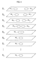
- FIG. 4 is a schematic diagram showing an example of a plurality of slices and vessel edges.
- FIG. 5 is a schematic diagram showing an example of location difference between vessel edges on adjacent slices.
- FIG. 6 is a schematic diagram showing an example of segmentation of vessel.
- FIG. 1 is a block diagram showing an illustrative embodiment of an ultrasound system 100 .
- the ultrasound system 100 comprises an ultrasound data acquisition unit 110 , a volume data forming unit 120 , a processor 130 , a display unit 140 and a control unit 150 .
- the ultrasound data acquisition unit 110 may be operable to transmit an ultrasound signal to a target object, receive the ultrasound signal (i.e., ultrasound echo signal) reflected from the target object, and acquire ultrasound data.
- an ultrasound signal i.e., ultrasound echo signal
- FIG. 2 is a block diagram showing an illustrative embodiment of the ultrasound data acquisition unit 110 .
- the ultrasound data acquisition unit 110 may include a transmit signal forming unit 210 , an ultrasound probe 220 including a plurality of transducer elements (not shown), a beam former 230 and an ultrasound data forming unit 240 .
- the transmit signal forming unit 210 may be operable to form a transmit signal to be applied to each of the transducer elements of the ultrasound probe 220 .
- the positions and focusing points of the transducer elements may be considered in forming the transmit signal.
- the transmit signal may include a transmit signal for acquiring a plurality of frames of the target object.
- the ultrasound probe 220 may operate to convert the transmit signal provided by the transmit signal forming unit 210 into an ultrasound signal and transmit it to the target object.
- the ultrasound probe 220 may further operate to receive the ultrasound echo signal reflected from the target object and form a receive signal.
- the beam former 230 may be configured to form a digital signal through analog-to-digital conversion of the receive signal provided by the ultrasound probe 220 .
- the beam former 230 may operate to perform receive-focusing upon the digital signal in consideration of the positions and focusing points of the transducer elements, and form a receive-focused signal thereby.
- the ultrasound data forming unit 240 may be configured to form ultrasound data of the target object using the receive-focused signal provided by the beam former 230 .
- the ultrasound data may comprise RF (radio frequency) data and IQ (in-phase/quardrature) data.
- the volume data forming unit 120 may operate to form volume data by using the ultrasound data provided by the ultrasound acquisition unit 110 .
- the volume data may comprise a plurality of frames and a plurality of voxels having brightness values.
- the processor 130 may operate to form a 3-dimensional ultrasound image including vessels in the target object by using the volume data provided by the volume data forming unit 120 , and perform segmentation of the vessels by using the 3-dimensional ultrasound image.
- FIG. 3 is a block diagram showing an illustrative embodiment of the processor 130 .
- the processor 130 comprises an image forming unit 310 , an edge detection unit 320 , a slice setting unit 330 and a segmentation unit 340 .
- the image forming unit 310 may operate to form the 3-dimensional ultrasound image through rendering of the volume data provided by the volume data forming unit 120 .
- the rendering may comprise ray-casting rendering, surface rendering, etc.
- the edge detection unit 320 may operate to detect vessel edges through performing edge detection on the 3-dimensional ultrasound image provided by the image forming unit 310 .
- the vessel edges may be detected by using an edge mask such as a Sobel mask, a Prewitt mask, a Robert mask, a Canny mask, etc.
- the vessel edges may be detected from the difference of eigen values by using a structure tensor.
- the slice setting unit 330 may operate to set a plurality of slices (S 0 -S n ) on the 3-dimensional ultrasound image in which the vessel edges were detected, as illustrated in FIG. 4 .
- the plurality of slices may comprise slices corresponding to the plurality of frames.
- the segmentation unit 340 may be configured to perform segmentation of the vessels based on a degree of registration between the respective vessels on the adjacent slices. In one embodiment, the segmentation unit 340 may operate to compare the location of vessels on adjacent slices by using the vessel edges and perform segmentation of the vessels. Following is illustrative operation of the segmentation unit 340 with reference to FIG. 4 .
- the segmentation unit 340 may operate to analyze a first slice (S 1 ) and detect vessel edges (VE 11 , VE 12 ) on the first slice (S 1 ).
- the segmentation unit 340 may operate to analyze a second slice (S 2 ) and detect vessel edges (VE 21 , VE 22 ) on the second slice (S 2 ).
- the segmentation unit 340 may operate to detect location difference between the vessel edges on the adjacent slices (i.e., the first slice (S 1 ) and the second slice (S 2 )), as illustrated in FIG. 5 .
- the segmentation unit 340 may operate to detect the location difference between the vessel edge (VE 11 ) of the first slice (S 1 ) and the vessel edge (VE 21 ) of the second slice (S 2 ) as well as the location difference between the vessel edge (VE 11 ) of the first slice (S 1 ) and the vessel edge (VE 22 ) of the second slice (S 2 ).
- the segmentation unit 340 may operate to detect the location difference between the vessel edge (VE 12 ) of the first slice (S 1 ) and the vessel edge (VE 21 ) of the second slice (S 2 ) as well as the location difference between the vessel edge (VE 12 ) of the first slice (S 1 ) and the vessel edge (VE 22 ) of the second slice (S 2 ).
- the segmentation unit 134 may connect the vessel edge (VE 21 ) of the second slice (S 2 ) with the vessel edge (VE 11 ) of the first slice (S 1 ), and connect the vessel edge (VE 22 ) of the second slice (S 2 ) with the vessel edge (VE 12 ) of the first slice (S 1 ) of the second slice (S 2 ) of the predetermined threshold
- the segmentation unit 340 may operate to analyze a fifth slice (S 5 ) and detect a vessel edge (VE 5 ) on the fifth slice (S 5 ).
- the segmentation unit 134 may operate to detect the location difference between the vessel edges on the adjacent slices (i.e., the fourth slice (S 4 ) and the fifth slice (S 5 )).
- the segmentation unit 340 may connect the vessel edge (VE 5 ) of the fifth slice (S 5 ) with the vessel edges (VE 41 , VE 41 ) of the fourth slice (S 4 ).
- the segmentation unit 340 may operate to analyze a sixth slice (S 6 ) and detect a vessel edge (VE 6 ) on the sixth slice (S 6 ).
- the segmentation unit 340 may operate to detect the location difference between the vessel edges on the adjacent slices (i.e., the fifth slice (S 5 ) and the sixth slice (S 6 )).
- the segmentation unit 340 may connect the vessel edge (VE 6 ) of the sixth slice (S 6 ) with the vessel edge (VE 5 ) of the fifth slice (S 5 ).
- the segmentation unit 340 may perform the same operation with respect to a seventh to an nth slice (S 7 -S n ) as described above in order to perform segmentation of the vessels, as illustrated in FIG. 6 .
- the display unit 140 may operate to display the 3-dimensional ultrasound image formed by the processor.
- the display unit 140 may further operate to display the 3-dimensional ultrasound image on which the processor 130 performed segmentation of the vessels.
- the display unit 140 may include a liquid crystal display (LCD), a cathode ray tube (CRT) or any other device capable of displaying an image.
- LCD liquid crystal display
- CRT cathode ray tube
- the control unit 150 may operate to control acquisition of the ultrasound data, and formation of the volume data and the 3-dimensional ultrasound image.
- the control unit 150 may further operate to control image processing of the 3-dimensional ultrasound image (i.e., segmentation of the vessels).
Abstract
Description
Claims (7)
Applications Claiming Priority (2)
| Application Number | Priority Date | Filing Date | Title |
|---|---|---|---|
| KR1020090072559A KR101014563B1 (en) | 2009-08-07 | 2009-08-07 | Ultrasound system and method for performing segmentation of vessel |
| KR10-2009-0072559 | 2009-08-07 |
Publications (2)
| Publication Number | Publication Date |
|---|---|
| US20110033096A1 US20110033096A1 (en) | 2011-02-10 |
| US8724873B2 true US8724873B2 (en) | 2014-05-13 |
Family
ID=42556939
Family Applications (1)
| Application Number | Title | Priority Date | Filing Date |
|---|---|---|---|
| US12/751,825 Active 2032-11-17 US8724873B2 (en) | 2009-08-07 | 2010-03-31 | Ultrasound system and method for segmenting vessels |
Country Status (4)
| Country | Link |
|---|---|
| US (1) | US8724873B2 (en) |
| EP (1) | EP2293242B1 (en) |
| JP (1) | JP5748970B2 (en) |
| KR (1) | KR101014563B1 (en) |
Families Citing this family (6)
| Publication number | Priority date | Publication date | Assignee | Title |
|---|---|---|---|---|
| KR101185728B1 (en) * | 2011-09-21 | 2012-09-25 | 주식회사 인피니트헬스케어 | A segmentatin method of medical image and apparatus thereof |
| KR101731512B1 (en) | 2012-07-30 | 2017-05-02 | 삼성전자주식회사 | Method of performing segmentation of vessel using a plurality of thresholds and device thereof |
| KR101937018B1 (en) * | 2016-03-24 | 2019-01-09 | 울산대학교 산학협력단 | Method and device for automatic inner and outer vessel wall segmentation in intravascular ultrasound images using deep learning |
| CN107274428B (en) * | 2017-08-03 | 2020-06-30 | 汕头市超声仪器研究所有限公司 | Multi-target three-dimensional ultrasonic image segmentation method based on simulation and actual measurement data |
| CN109711333B (en) * | 2018-12-26 | 2022-10-18 | 西安科技大学 | Ultrasonic signal receiving and processing method based on signal section segmentation |
| KR102641346B1 (en) | 2022-10-14 | 2024-02-27 | 주식회사 에어스메디컬 | Vessel detection method and computer program performing the same |
Citations (14)
| Publication number | Priority date | Publication date | Assignee | Title |
|---|---|---|---|---|
| JPH05137728A (en) | 1991-11-25 | 1993-06-01 | Hitachi Medical Corp | Three-dimensional image generating method in ultrasonic diagnostic device |
| JPH07178086A (en) | 1993-12-21 | 1995-07-18 | Toshiba Corp | Method for ultrasonic diagnosis and system therefor |
| JPH07178090A (en) | 1993-12-24 | 1995-07-18 | Ge Yokogawa Medical Syst Ltd | Method and system for continuum distinction and ultrasonic bloodstream display |
| WO1997000482A1 (en) | 1995-06-15 | 1997-01-03 | The Regents Of The University Of Michigan | Method and apparatus for composition and display of three-dimensional image from two-dimensional ultrasound |
| KR20010014491A (en) | 1999-02-19 | 2001-02-26 | 더 존 피. 로바츠 리서치 인스티튜트 | Semi-automated segmentation method for 3-dimensional ultrasound |
| US6390984B1 (en) * | 2000-09-14 | 2002-05-21 | Ge Medical Systems Global Technology Company, Llc | Method and apparatus for locking sample volume onto moving vessel in pulsed doppler ultrasound imaging |
| US6424732B1 (en) | 1998-12-01 | 2002-07-23 | The Board Of Trustees Of The Leland Stanford Junior University | Object segregation in images |
| WO2005048190A1 (en) | 2003-11-13 | 2005-05-26 | Centre Hospitalier De L'universite De Montreal (Chum) | Automatic multi-dimensional intravascular ultrasound image segmentation method |
| US20060020204A1 (en) * | 2004-07-01 | 2006-01-26 | Bracco Imaging, S.P.A. | System and method for three-dimensional space management and visualization of ultrasound data ("SonoDEX") |
| US20070201737A1 (en) | 2003-11-26 | 2007-08-30 | Wenli Cai | System And Method For Vascular Visualization Using Planar Reformation Of Vascular Central Axis Surface With Biconvex Slab |
| JP2007524445A (en) | 2003-06-17 | 2007-08-30 | ブラウン ユニバーシティ | Method and apparatus for model-based detection of structures in projection data |
| US20070242869A1 (en) * | 2006-04-12 | 2007-10-18 | Eastman Kodak Company | Processing and measuring the spine in radiographs |
| JP5137728B2 (en) | 2008-07-30 | 2013-02-06 | Hoya株式会社 | Endoscope |
| US8515145B2 (en) | 2003-06-17 | 2013-08-20 | Brown University | Methods and apparatus for identifying subject matter in view data |
-
2009
- 2009-08-07 KR KR1020090072559A patent/KR101014563B1/en active IP Right Grant
-
2010
- 2010-03-26 EP EP10157865.6A patent/EP2293242B1/en active Active
- 2010-03-31 US US12/751,825 patent/US8724873B2/en active Active
- 2010-07-30 JP JP2010172680A patent/JP5748970B2/en not_active Expired - Fee Related
Patent Citations (18)
| Publication number | Priority date | Publication date | Assignee | Title |
|---|---|---|---|---|
| JPH05137728A (en) | 1991-11-25 | 1993-06-01 | Hitachi Medical Corp | Three-dimensional image generating method in ultrasonic diagnostic device |
| JPH07178086A (en) | 1993-12-21 | 1995-07-18 | Toshiba Corp | Method for ultrasonic diagnosis and system therefor |
| JPH07178090A (en) | 1993-12-24 | 1995-07-18 | Ge Yokogawa Medical Syst Ltd | Method and system for continuum distinction and ultrasonic bloodstream display |
| WO1997000482A1 (en) | 1995-06-15 | 1997-01-03 | The Regents Of The University Of Michigan | Method and apparatus for composition and display of three-dimensional image from two-dimensional ultrasound |
| JP2001504603A (en) | 1995-06-15 | 2001-04-03 | ザ・リージエント・オブ・ザ・ユニバーシテイ・オブ・ミシガン | Method and apparatus for constructing and displaying a three-dimensional image from two-dimensional ultrasound |
| US6424732B1 (en) | 1998-12-01 | 2002-07-23 | The Board Of Trustees Of The Leland Stanford Junior University | Object segregation in images |
| KR20010014491A (en) | 1999-02-19 | 2001-02-26 | 더 존 피. 로바츠 리서치 인스티튜트 | Semi-automated segmentation method for 3-dimensional ultrasound |
| US6251072B1 (en) | 1999-02-19 | 2001-06-26 | Life Imaging Systems, Inc. | Semi-automated segmentation method for 3-dimensional ultrasound |
| US6390984B1 (en) * | 2000-09-14 | 2002-05-21 | Ge Medical Systems Global Technology Company, Llc | Method and apparatus for locking sample volume onto moving vessel in pulsed doppler ultrasound imaging |
| JP2007524445A (en) | 2003-06-17 | 2007-08-30 | ブラウン ユニバーシティ | Method and apparatus for model-based detection of structures in projection data |
| US8515145B2 (en) | 2003-06-17 | 2013-08-20 | Brown University | Methods and apparatus for identifying subject matter in view data |
| WO2005048190A1 (en) | 2003-11-13 | 2005-05-26 | Centre Hospitalier De L'universite De Montreal (Chum) | Automatic multi-dimensional intravascular ultrasound image segmentation method |
| JP2007512862A (en) | 2003-11-13 | 2007-05-24 | サントル・オスピタリエ・ドゥ・リュニヴェルシテ・ドゥ・モントリオール | Method of automatic multidimensional intravascular ultrasound image segmentation |
| US20070165916A1 (en) | 2003-11-13 | 2007-07-19 | Guy Cloutier | Automatic multi-dimensional intravascular ultrasound image segmentation method |
| US20070201737A1 (en) | 2003-11-26 | 2007-08-30 | Wenli Cai | System And Method For Vascular Visualization Using Planar Reformation Of Vascular Central Axis Surface With Biconvex Slab |
| US20060020204A1 (en) * | 2004-07-01 | 2006-01-26 | Bracco Imaging, S.P.A. | System and method for three-dimensional space management and visualization of ultrasound data ("SonoDEX") |
| US20070242869A1 (en) * | 2006-04-12 | 2007-10-18 | Eastman Kodak Company | Processing and measuring the spine in radiographs |
| JP5137728B2 (en) | 2008-07-30 | 2013-02-06 | Hoya株式会社 | Endoscope |
Non-Patent Citations (6)
| Title |
|---|
| Extended European Search Report for EP 10157865.6-2218, 7 pages, dated Nov. 16, 2010. |
| Japanese Office Action issued in Japanese Application No. 2010-172680 mailed Mar. 18, 2014, with English translation. |
| Kirbas et al., "A Review of Vessel Extraction Techniques and Algorithms," ACM Computing Surveys, 36(2): 81-121 (Jun. 2004). |
| Korean Office Action issued in Korean Patent Application No. KR 10-2009-0072559 dated Jan. 12, 2011. |
| M. Lenic et al., "Fast Segmentation of Ovarian Ultrasound Volumes Using Support Vector Machines and Sparse Learning Sets," New Direct. In Interac. Multimedia, SCI 142, pp. 95-105, 2008. |
| Noble et al., "Ultrasound Image Segmentation: A Survey," IEEE Transactions on Medical Imaging, 25(8): 987-1010 (Aug. 2006). |
Also Published As
| Publication number | Publication date |
|---|---|
| JP2011036653A (en) | 2011-02-24 |
| JP5748970B2 (en) | 2015-07-15 |
| KR101014563B1 (en) | 2011-02-16 |
| KR20110015058A (en) | 2011-02-15 |
| EP2293242B1 (en) | 2019-05-01 |
| US20110033096A1 (en) | 2011-02-10 |
| EP2293242A1 (en) | 2011-03-09 |
Similar Documents
| Publication | Publication Date | Title |
|---|---|---|
| EP1779289B1 (en) | Diagnostic system for multimodality mammography | |
| CN109846513B (en) | Ultrasonic imaging method, ultrasonic imaging system, image measuring method, image processing system, and medium | |
| US8724873B2 (en) | Ultrasound system and method for segmenting vessels | |
| JP5002260B2 (en) | Medical diagnostic imaging equipment | |
| US9069062B2 (en) | Surface rendering for volume data in an ultrasound system | |
| KR101175426B1 (en) | Ultrasound system and method for providing three-dimensional ultrasound image | |
| US8606045B2 (en) | Image based registration using transform and second images of a target object | |
| KR20110013026A (en) | System and method for providing 2-dimensional ct image corresponding to 2-dimensional ultrasound image | |
| JP2011083600A (en) | Ultrasonic system and method for detecting object of interest based on luminance value of the object of interest | |
| US20150190120A1 (en) | Method and system for processing ultrasonic imaging data | |
| US8517947B2 (en) | Ultrasound system and method for performing vessel labeling | |
| US20160302771A1 (en) | 3d ultrasound system and method for operating 3d ultrasound system | |
| US8663110B2 (en) | Providing an optimal ultrasound image for interventional treatment in a medical system | |
| JP5642997B2 (en) | Ultrasound system and method for providing multiple slice images | |
| US20120108962A1 (en) | Providing a body mark in an ultrasound system | |
| KR101117913B1 (en) | Ultrasound system and method for rendering volume data | |
| KR101024857B1 (en) | Ultrasound system and method for performing color modeling processing on three-dimensional ultrasound image | |
| KR101067230B1 (en) | Ultrasound system and method for controlling storage of volume data | |
| KR20110039506A (en) | Ultrasound system and method for compensating volume data | |
| KR101097630B1 (en) | Ultrasound system and method for providing measurement information of target object based on three-dimensional ultrasound data | |
| EP2454996A1 (en) | Providing an optimal ultrasound image for interventional treatment in a medical system |
Legal Events
| Date | Code | Title | Description |
|---|---|---|---|
| AS | Assignment |
Owner name: MEDISON CO., LTD., KOREA, REPUBLIC OF Free format text: ASSIGNMENT OF ASSIGNORS INTEREST;ASSIGNORS:LEE, JUN KYO;HYUN, DONG GYU;YOO, JAE HEUNG;REEL/FRAME:024171/0081 Effective date: 20100318 |
|
| FEPP | Fee payment procedure |
Free format text: PAYOR NUMBER ASSIGNED (ORIGINAL EVENT CODE: ASPN); ENTITY STATUS OF PATENT OWNER: LARGE ENTITY |
|
| STCF | Information on status: patent grant |
Free format text: PATENTED CASE |
|
| AS | Assignment |
Owner name: SAMSUNG MEDISON CO., LTD., KOREA, REPUBLIC OF Free format text: CHANGE OF NAME;ASSIGNOR:MEDISON CO., LTD.;REEL/FRAME:032874/0741 Effective date: 20110329 |
|
| MAFP | Maintenance fee payment |
Free format text: PAYMENT OF MAINTENANCE FEE, 4TH YEAR, LARGE ENTITY (ORIGINAL EVENT CODE: M1551) Year of fee payment: 4 |
|
| MAFP | Maintenance fee payment |
Free format text: PAYMENT OF MAINTENANCE FEE, 8TH YEAR, LARGE ENTITY (ORIGINAL EVENT CODE: M1552); ENTITY STATUS OF PATENT OWNER: LARGE ENTITY Year of fee payment: 8 |