US8509877B2 - Endoscope insertion support system and endoscope insertion support method - Google Patents
Endoscope insertion support system and endoscope insertion support method Download PDFInfo
- Publication number
- US8509877B2 US8509877B2 US12/260,630 US26063008A US8509877B2 US 8509877 B2 US8509877 B2 US 8509877B2 US 26063008 A US26063008 A US 26063008A US 8509877 B2 US8509877 B2 US 8509877B2
- Authority
- US
- United States
- Prior art keywords
- voi
- section
- volume area
- area
- organ
- Prior art date
- Legal status (The legal status is an assumption and is not a legal conclusion. Google has not performed a legal analysis and makes no representation as to the accuracy of the status listed.)
- Active, expires
Links
Images


Classifications
-
- A—HUMAN NECESSITIES
- A61—MEDICAL OR VETERINARY SCIENCE; HYGIENE
- A61B—DIAGNOSIS; SURGERY; IDENTIFICATION
- A61B1/00—Instruments for performing medical examinations of the interior of cavities or tubes of the body by visual or photographical inspection, e.g. endoscopes; Illuminating arrangements therefor
- A61B1/04—Instruments for performing medical examinations of the interior of cavities or tubes of the body by visual or photographical inspection, e.g. endoscopes; Illuminating arrangements therefor combined with photographic or television appliances
-
- A—HUMAN NECESSITIES
- A61—MEDICAL OR VETERINARY SCIENCE; HYGIENE
- A61B—DIAGNOSIS; SURGERY; IDENTIFICATION
- A61B1/00—Instruments for performing medical examinations of the interior of cavities or tubes of the body by visual or photographical inspection, e.g. endoscopes; Illuminating arrangements therefor
- A61B1/00002—Operational features of endoscopes
- A61B1/00004—Operational features of endoscopes characterised by electronic signal processing
- A61B1/00009—Operational features of endoscopes characterised by electronic signal processing of image signals during a use of endoscope
-
- A—HUMAN NECESSITIES
- A61—MEDICAL OR VETERINARY SCIENCE; HYGIENE
- A61B—DIAGNOSIS; SURGERY; IDENTIFICATION
- A61B1/00—Instruments for performing medical examinations of the interior of cavities or tubes of the body by visual or photographical inspection, e.g. endoscopes; Illuminating arrangements therefor
- A61B1/267—Instruments for performing medical examinations of the interior of cavities or tubes of the body by visual or photographical inspection, e.g. endoscopes; Illuminating arrangements therefor for the respiratory tract, e.g. laryngoscopes, bronchoscopes
- A61B1/2676—Bronchoscopes
-
- A—HUMAN NECESSITIES
- A61—MEDICAL OR VETERINARY SCIENCE; HYGIENE
- A61B—DIAGNOSIS; SURGERY; IDENTIFICATION
- A61B5/00—Measuring for diagnostic purposes; Identification of persons
- A61B5/103—Detecting, measuring or recording devices for testing the shape, pattern, colour, size or movement of the body or parts thereof, for diagnostic purposes
-
- A—HUMAN NECESSITIES
- A61—MEDICAL OR VETERINARY SCIENCE; HYGIENE
- A61B—DIAGNOSIS; SURGERY; IDENTIFICATION
- A61B5/00—Measuring for diagnostic purposes; Identification of persons
- A61B5/41—Detecting, measuring or recording for evaluating the immune or lymphatic systems
- A61B5/414—Evaluating particular organs or parts of the immune or lymphatic systems
- A61B5/418—Evaluating particular organs or parts of the immune or lymphatic systems lymph vessels, ducts or nodes
Definitions
- the present invention relates to an endoscope insertion support system and an endoscope insertion support method for supporting the insertion of an endoscope into the tubular path of a tubular organ.
- a spiral continuous scan (helical scan) is performed on a three-dimensional area of the subject, and a three-dimensional image is produced from consecutively sliced tomograms of the three-dimensional area.
- One of such three-dimensional images is a three-dimensional image of the bronchus of a lung.
- a three-dimensional image of a bronchus is used for three-dimensionally identifying the position of a disordered part suspected of presence of lung cancer or the like. Then, in order to check the disordered part by biopsy, a bronchoscope is inserted and a sample of the tissue is picked up by extruding from its distal end portion a bioptic needle, bioptic forceps or the like.
- Japanese Patent Application Laid-Open No. 2000-135215 as Document 1 proposes an apparatus by which (1) a three-dimensional image of a tubular path in a subject is produced on the basis of image data of a three-dimensional area in the subject, (2) the route to the target point is figured out along the tubular path on the three-dimensional image, (3) a virtual endoscopic image of the tubular path along the route is produced on the basis of the image data, and (4) a bronchoscope is navigated to the target region by displaying the virtual endoscopic image.
- An endoscope insertion support system of one aspect of the present invention is provided with: a volume area setting section for setting a volume area which has a start point set in a tubular path of a tubular organ within three-dimensional image data of a subject and has a size so prescribed as to contain the tubular organ; an organ area information calculating section which extracts tubular area information in the volume area on the basis of the three-dimensional image data of the tubular organ in the volume area and calculates segmentation data representing a tubular path shape; a contained state determining section which determines whether or not the tubular path is contained in the volume area set by the volume area setting section; a heteromorphic state detecting section which detects a heteromorphic state of the tubular path shape on the basis of a result of calculation of the organ area information; and a hierarchical volume area setting section which sets a hierarchical volume area obtained by hierarchically linking to the volume area set by the volume area setting section to a size based on a result of determination by the contained state determining section and a
- Such the endoscope insertion support system has an effect of enabling a volume area to be effectively set in a tubular organ having a heteromorphic part and tubular path area information on the tubular organ to be correctly extracted.
- the hierarchical volume area setting section sets a next-step hierarchical volume area which further hierarchically links to the hierarchical volume area
- the organ area information calculating section calculates segmentation data representing a tubular path shape in the next-step hierarchical volume area
- the heteromorphic state detecting section detects a heteromorphic state of the tubular path shape in the hierarchical volume area on the basis of a result of calculation of the organ area information
- the hierarchical volume area setting section controls the size of the next-step hierarchical volume area on the basis of the detected heteromorphic state.
- Such the endoscope insertion support system has an effect of enabling a volume area to be effectively set in a tubular organ having a region bent at or beyond a prescribed curvature and area information on the tubular organ to be correctly extracted.
- the endoscope insertion support system preferably further includes a volume area altering section which extends or contracts a distance between end faces of the volume area.
- Such the endoscope insertion support system has an effect of enabling a volume area to be effectively set in a noted part in a tubular organ and area information on the tubular organ to be correctly extracted.
- the endoscope insertion support system preferably further includes a direction determining section which determines the extending/contracting direction of the volume area or the hierarchical volume area, and the volume area altering section extends or contracts the distance between the end faces of the volume area or the hierarchical volume area on the basis of a result of determination by the direction determining section.
- Such the endoscope insertion support system has an effect of enabling the extending/contracting direction of the volume area or the hierarchical volume area appropriately to match the shape of the tubular path and processing time to be shortened.
- the heteromorphic state detecting section detects as at least a heteromorphic state a strictured or expanded state of the tubular path in an end section of the hierarchical volume area on the basis of at least one of a diameter, area and circumferential length out of the segmentation data.
- the endoscope insertion support system detects as a heteromorphic state a strictured or expanded state of the tubular path in the end section of the hierarchical volume area in relation to at least one of a diameter, area and circumferential length out of the segmentation data, the endoscope insertion support system is capable of detecting a heteromorphic state similarly to an actual system.
- the contained state determining section determines the contained state of the tubular path on the basis of detection of branching hole in the tubular path in an end face of the volume area or the hierarchical volume area.
- Such the endoscope insertion support system has an effect of enabling the contained state of the tubular path in the volume area or the hierarchical volume area to be appropriately determined and area information on the tubular organ to be correctly extracted.
- the contained state determining section determines the contained state of the tubular path organ on the basis of detection of the tubular organ on a side face of the volume area or the hierarchical volume area.
- Such the endoscope insertion support system has an effect of enabling the contained state of the tubular path in the volume area or the hierarchical volume area to be appropriately determined and area information on the tubular organ to be correctly extracted.
- the endoscope insertion support system preferably further includes a route setting section which sets a line connecting gravity center points of tubular path sections at least in the vicinities of end faces of the volume area and the hierarchical volume area as a substantial center line to be an endoscope insertion support route.
- Such the endoscope insertion support system has an effect of achieving nothing inferior to a locus of the endoscope tip at the time of inserting an actual endoscope by having the route pass the gravity center points of tubular path sections.
- the endoscopic insertion support route is set by curvilinearly correcting the substantial center line.
- Such the endoscope insertion support system has an effect of achieving nothing inferior to the locus of the endoscope tip at the time of inserting an actual endoscope by making route a smooth curve.
- the endoscope insertion support system preferably further includes: a multiplanar reformation image generating section which generates a multiplanar reformation image in the subject on the basis of the three-dimensional image data of the subject; and a start point designating section which designates the start point on the generated multiplanar reformation image.
- Such the endoscope insertion support system has an effect of enabling a position intended by a user to be accurately acquired by having the start point designated on the multiplanar reformation image.
- coordinates of the start point designated by the start point coordinates designating section are coordinates near the end faces of the volume area or the hierarchical volume area.
- Such the endoscope insertion support system has an effect of enabling organ to be extracted from the vicinity of the start point, any unintended area of the organ to be prevented from extraction and the processing time to be shortened.
- the tubular organ is one of bronchus, blood vessel, large intestine, small intestine or lymphatic vessel.
- Such the endoscope insertion support system has an effect of enabling appropriate endoscopic diagnosis and treatment to be accomplished by presenting tubular information on any one of bronchus, blood vessel, large intestine, small intestine, pancreas duct, bile duct or lymphatic vessel.
- the present invention has an effect of enabling a VOI (Volume of Interest) to be effectively set in a tubular organ having a strictured part and tubular path area information on a tubular organ to be correctly extracted.
- VOI Volume of Interest
- FIG. 1 is a configurational diagram showing the configuration of a bronchoscope insertion support system pertaining to Embodiment 1 of the invention
- FIG. 2 is a functional block diagram showing the configuration of the VOI generation setting section of FIG. 1 ;
- FIG. 3 is a flow chart illustrating the actions of the bronchoscope insertion support system of FIG. 1 ;
- FIG. 4 is a diagram showing a patient information selecting screen developed by the processing of FIG. 3 ;
- FIG. 5 is a diagram showing an MPR screen generated by the MPR image generating section of FIG. 1 ;
- FIG. 6 is a schematic diagram of a bronchus schematically showing a start point set on the MPR screen of FIG. 5 ;
- FIG. 7 is a schematic diagram of a bronchus schematically showing a route set on the MPR screen of FIG. 5 ;
- FIG. 8 is a flow chart showing the flow of processing of FIG. 3 to extract bronchial area information
- FIG. 9 is a flow chart showing the flow of processing of FIG. 8 to arrange and register a new VOI
- FIG. 10 is a first drawing illustrating the processing of FIG. 8 to extract bronchial area information
- FIG. 11 is a second drawing illustrating the processing of FIG. 8 to extract bronchial area information
- FIG. 12 is a third drawing illustrating the processing of FIG. 8 to extract bronchial area information
- FIG. 13 is a fourth drawing illustrating the processing of FIG. 8 to extract bronchial area information
- FIG. 14 is a fifth drawing illustrating the processing of FIG. 8 to extract bronchial area information
- FIG. 15 is a sixth drawing illustrating the processing of FIG. 8 to extract bronchial area information
- FIG. 16 is a seventh drawing illustrating the processing of FIG. 8 to extract bronchial area information
- FIG. 17 is an eighth drawing illustrating the processing of FIG. 8 to extract bronchial area information
- FIG. 18 is a ninth drawing illustrating the processing of FIG. 8 to extract bronchial area information
- FIG. 19 is a 10th drawing illustrating the processing of FIG. 8 to extract bronchial area information
- FIG. 20 is an 11th drawing illustrating the processing of FIG. 8 to extract bronchial area information
- FIG. 21 is a 12th drawing illustrating the processing of FIG. 8 to extract bronchial area information
- FIG. 22 is a 13th drawing illustrating the processing of FIG. 8 to extract bronchial area information
- FIG. 23 is a 14th drawing illustrating the processing of FIG. 8 to extract bronchial area information
- FIG. 24 is a 15th drawing illustrating the processing of FIG. 8 to extract bronchial area information
- FIG. 25 is a 16th drawing illustrating the processing of FIG. 8 to extract bronchial area information
- FIG. 26 is a 17th drawing illustrating the processing of FIG. 8 to extract bronchial area information
- FIG. 27 is a first drawing illustrating the processing to arrange and register a new VOI of FIG. 9 ;
- FIG. 28 is a second drawing illustrating the processing to arrange and register a new VOI of FIG. 9 ;
- FIG. 29 is a third drawing illustrating the processing to arrange and register a new VOI of FIG. 9 ;
- FIG. 30 is a fourth drawing illustrating the processing to arrange and register a new VOI of FIG. 9 ;
- FIG. 31 is a first drawing illustrating the processing of FIG. 8 to extract a branching point
- FIG. 32 is a second drawing illustrating the processing of FIG. 8 to extract a branching point
- FIG. 33 is a first drawing illustrating the processing of FIG. 8 to determine a bronchial area section
- FIG. 34 is a second drawing illustrating the processing of FIG. 8 to determine a bronchial area section
- FIG. 35 is a third drawing illustrating the processing of FIG. 8 to determine a bronchial area section
- FIG. 36 is a fourth drawing illustrating the processing of FIG. 8 to determine a bronchial area section
- FIG. 37 is a fifth drawing illustrating the processing of FIG. 8 to determine a bronchial area section
- FIG. 38 is a flow chart showing the conventional flow of processing to extract bronchial area information compared with the processing of FIG. 8 to extract bronchial area information;
- FIG. 39 is a first drawing illustrating the processing of FIG. 38 to extract bronchial area information
- FIG. 40 is a second drawing illustrating the processing of FIG. 38 to extract bronchial area information
- FIG. 41 is a third drawing illustrating the processing of FIG. 38 to extract bronchial area information
- FIG. 42 is a fourth drawing illustrating the processing of FIG. 38 to extract bronchial area information
- FIG. 43 is an 18th drawing illustrating the processing of FIG. 8 to extract bronchial area information
- FIG. 44 is a 19th drawing illustrating the processing of FIG. 8 to extract bronchial area information
- FIG. 45 is a 20th drawing illustrating the processing of FIG. 8 to extract bronchial area information
- FIG. 46 is a 21st drawing illustrating the processing of FIG. 8 to extract bronchial area information
- FIG. 47 is a first drawing illustrating route setting by the route setting section of FIG. 1 ;
- FIG. 48 is a second drawing illustrating route setting by the route setting section of FIG. 1 ;
- FIG. 49 is a third drawing illustrating route setting by the route setting section of FIG. 1 ;
- FIG. 50 is a fourth drawing illustrating route setting by the route setting section of FIG. 1 ;
- FIG. 51 is a drawing illustrating the processing to bend by the route setting section of FIG. 1 ;
- FIG. 52 is a drawing showing the route having undergone the bend processing of FIG. 51 ;
- FIG. 53 is a drawing showing an insertion support screen generated by the endoscope insertion support apparatus of FIG. 1 ;
- FIG. 54 is a drawing showing a modified example of a VOI generated by the VOI generation setting section of FIG. 1 .
- FIG. 1 through FIG. 54 pertain to Embodiment 1 of the invention, wherein FIG. 1 is a configurational diagram showing the configuration of a bronchoscope insertion support system; FIG. 2 , a functional block diagram showing the configuration of the VOI generation setting section of FIG. 1 ; FIG. 3 , a flow chart illustrating the actions of the bronchoscope insertion support system of FIG. 1 ; FIG. 4 , a diagram showing a patient information selecting screen developed by the processing of FIG. 3 ; FIG. 5 , a diagram showing an MPR screen generated by the MPR image generating section of FIG. 1 ; FIG.
- FIG. 6 a schematic diagram of a bronchus schematically showing a start point set on the MPR (multiplanar reformation image) screen of FIG. 5 ;
- FIG. 7 a schematic diagram of a bronchus schematically showing a route set on the MPR screen of FIG. 5 ;
- FIG. 8 a flow chart showing the flow of processing of FIG. 3 to extract bronchial area information;
- FIG. 9 is a flow chart showing the flow of processing of FIG. 8 to arrange and register a new VOI;
- FIG. 10 a first drawing illustrating the processing of FIG. 8 to extract bronchial area information.
- FIG. 11 is a second drawing illustrating the processing of FIG. 8 to extract bronchial area information
- FIG. 12 a third drawing illustrating the processing of FIG. 8 to extract bronchial area information
- FIG. 13 a fourth drawing illustrating the processing of FIG. 8 to extract bronchial area information
- FIG. 14 a fifth drawing illustrating the processing of FIG. 8 to extract bronchial area information
- FIG. 15 a sixth drawing illustrating the processing of FIG. 8 to extract bronchial area information
- FIG. 16 a seventh drawing illustrating the processing of FIG. 8 to extract bronchial area information
- FIG. 17 an eighth drawing illustrating the processing of FIG. 8 to extract bronchial area information
- FIG. 11 is a second drawing illustrating the processing of FIG. 8 to extract bronchial area information
- FIG. 12 a third drawing illustrating the processing of FIG. 8 to extract bronchial area information
- FIG. 13 a fourth drawing illustrating the processing of FIG. 8 to extract bronchial area information
- FIG. 14
- FIG. 18 a ninth drawing illustrating the processing of FIG. 8 to extract bronchial area information
- FIG. 19 a 10th drawing illustrating the processing of FIG. 8 to extract bronchial area information
- FIG. 20 an 11th drawing illustrating the processing of FIG. 8 to extract bronchial area information.
- FIG. 21 is a 12th drawing illustrating the processing of FIG. 8 to extract bronchial area information
- FIG. 22 a 13th drawing illustrating the processing of FIG. 8 to extract bronchial area information
- FIG. 23 a 14th drawing illustrating the processing of FIG. 8 to extract bronchial area information
- FIG. 24 a 15th drawing illustrating the processing of FIG. 8 to extract bronchial area information
- FIG. 25 a 16th drawing illustrating the processing of FIG. 8 to extract bronchial area information
- FIG. 26 a 17th drawing illustrating the processing of FIG. 8 to extract bronchial area information
- FIG. 27 a first drawing illustrating the processing to arrange and register a new VOI of FIG. 9 ;
- FIG. 28 a second drawing illustrating the processing to arrange and register a new VOI of FIG. 9 ;
- FIG. 29 is a third drawing illustrating the processing to arrange and register a new VOI of FIG. 9 ;
- FIG. 30 a fourth drawing illustrating the processing to arrange and register a new VOI of FIG. 9 .
- FIG. 31 is a first drawing illustrating the processing of FIG. 8 to extract a branching point
- FIG. 32 a second drawing illustrating the processing of FIG. 8 to extract a branching point
- FIG. 33 a first drawing illustrating the processing of FIG. 8 to determine a bronchial area section
- FIG. 34 a second drawing illustrating the processing of FIG. 8 to determine a bronchial area section
- FIG. 35 a third drawing illustrating the processing of FIG. 8 to determine a bronchial area section
- FIG. 36 a fourth drawing illustrating the processing of FIG. 8 to determine a bronchial area section
- FIG. 37 a fifth drawing illustrating the processing of FIG. 8 to determine a bronchial area section
- FIG. 31 is a first drawing illustrating the processing of FIG. 8 to extract a branching point
- FIG. 32 a second drawing illustrating the processing of FIG. 8 to extract a branching point
- FIG. 33 a first drawing illustrating the processing of FIG. 8 to determine a bron
- FIG. 38 a flow chart showing the conventional flow of processing to extract bronchial area information compared with the processing of FIG. 8 to extract bronchial area information
- FIG. 39 a first drawing illustrating the processing of FIG. 38 to extract bronchial area information
- FIG. 40 a second drawing illustrating the processing of FIG. 38 to extract bronchial area information.
- FIG. 41 is a third drawing illustrating the processing of FIG. 38 to extract bronchial area information
- FIG. 42 a fourth drawing illustrating the processing of FIG. 38 to extract bronchial area information
- FIG. 43 an 18th drawing illustrating the processing of FIG. 8 to extract bronchial area information
- FIG. 44 a 19th drawing illustrating the processing of FIG. 8 to extract bronchial area information
- FIG. 45 a 20th drawing illustrating the processing of FIG. 8 to extract bronchial area information
- FIG. 46 a 21st drawing illustrating the processing of FIG. 8 to extract bronchial area information
- FIG. 47 a first drawing illustrating route setting by the route setting section of FIG. 1 ;
- FIG. 47 a first drawing illustrating route setting by the route setting section of FIG. 1 ;
- FIG. 47 a first drawing illustrating route setting by the route setting section of FIG. 1 ;
- FIG. 47 a first drawing illustrating route setting by the route setting section of FIG. 1 ;
- FIG. 47
- FIG. 48 a second drawing illustrating route setting by the route setting section of FIG. 1 ;
- FIG. 49 a third drawing illustrating route setting by the route setting section of FIG. 1 ;
- FIG. 50 a fourth drawing illustrating route setting by the route setting section of FIG. 1 .
- FIG. 51 is a drawing illustrating the processing to bend by the route setting section of FIG. 1 ;
- FIG. 52 a drawing showing the route having undergone the bend processing of FIG. 51 ;
- FIG. 53 a drawing showing an insertion support screen generated by the endoscope insertion support apparatus of FIG. 1 ;
- FIG. 54 a drawing showing a modified example of a VOI generated by the VOI generation setting section of FIG. 1 .
- a bronchoscope insertion support system 1 as the endoscope insertion support system of the present embodiment comprises a bronchoscope apparatus 2 and an endoscope insertion support apparatus 6 as an apparatus for extracting the bronchial shape.
- the endoscope insertion support apparatus 6 extracts the bronchial shape on the basis of CT image data, and generates a virtual endoscopic image of the inside of the bronchus (hereinafter referred to as VBS image). Then, an endoscopic image of the inside of the bronchus obtained by the bronchoscope apparatus 2 (hereinafter referred to as live image) and the VBS image are synthesized to display a synthetic image on a monitor 5 to support insertion of the bronchoscope apparatus 2 into the bronchus.
- VBS image virtual endoscopic image of the inside of the bronchus obtained by the bronchoscope apparatus 2
- live image an endoscopic image of the inside of the bronchus obtained by the bronchoscope apparatus 2
- VBS image an endoscopic image of the inside of the bronchus obtained by the bronchoscope apparatus 2
- live image an endoscopic image of the inside of the bronchus obtained by the bronchoscope apparatus 2
- VBS image an endoscopic image of the inside of the bronchus
- the bronchoscope apparatus 2 comprises a bronchoscope having an image pickup section, a light source which supplies illuminating light to the bronchoscope, a camera control unit which subjects image pickup signals from the bronchoscope to signal process, and so forth.
- the bronchoscope apparatus 2 then inserts the bronchoscope into the bronchus within the body of a patient and subjects a target tissue to biopsy while picking up images of the inside of the bronchus.
- the endoscope insertion support apparatus 6 synthesizes the live image and the VBS image, and also displays a synthetic image on an operational monitor 7 .
- the operational monitor 7 is provided with an input section 8 made up of a touch panel, and it is made possible to easily operate the input section 8 made up of a touch panel while manually inserting the bronchoscope.
- the endoscope insertion support apparatus 6 comprises a CT image data capturing section 10 , a CT image data storage section 11 , an MPR image generating section 12 as a multiplanar reformation image generating section, and a VOI (Volume of Interest; hereinafter referred to simply as VOI) generation setting section 13 as a volume area setting section and a hierarchical volume area setting section, an organ area extracting section 14 as an organ area information calculating section and a heteromorphic state detecting section, a route setting section 15 as a route setting section, a VBS image generating section 16 , a VBS image storage section 17 , an image processing section 18 , an image display control section 19 and a setting information input section 20 .
- VOI Volume of Interest
- the CT image data capturing section 10 captures three-dimensional image data generated by a known CT apparatus, not shown, for picking up X-ray tomograms of the patient via a portable storage medium such as an MO (Magnetic Optical disk) apparatus or a DVD (Digital Versatile Disk) apparatus, for instance.
- a portable storage medium such as an MO (Magnetic Optical disk) apparatus or a DVD (Digital Versatile Disk) apparatus, for instance.
- the CT image data storage section 11 stores the CT image data captured by the CT image data capturing section 10 .
- the MPR image generating section 12 generates an MPR image (multiplanar reformation image) on the basis of the CT image data stored in the CT image data storage section 11 .
- the VOI generation setting section 13 sets a VOI of a prescribed size on the CT image data, including the start point set on the MPR image by the setting information input section 20 , stored in the CT image data storage section 11 .
- the VOI generation setting section 13 has a function to extend the set VOI or altering its direction by turning it or to set a new VOI with a new optional position as the initial point. Details will be described later on.
- the organ area extracting section 14 extracts tubular path area information (including at least the inner wall face of the tubular path) of the tubular organ from the CT image data in the VOI set by the VOI generation setting section 13 (hereinafter referred to as segmentation processing). Further the organ area extracting section 14 links the tubular path area information obtained by segmentation processing of an organ structure with respect to each of a plurality of VOI set by the VOI generation setting section 13 , and executes processing to extract tubular path area information on the whole bronchus. Specific processing by the organ area extracting section 14 will be described afterwards.
- the route setting section 15 sets the optimal insertion route for supporting within the bronchus from the start point of support, where insertion support is started by the setting information input section 20 , to the target, which is the end point of support, from the tubular path area information on the whole bronchus extracted by the organ area extracting section 14 .
- the VBS image generating section 16 generates frame by frame consecutive VBS images on the route set by the route setting section 15 on the basis of the CT image data stored in the CT image data storage section 11 .
- the VBS image storage section 17 stores the VBS images generated by the VBS image generating section 16 .
- the image processing section 18 inputs image pickup signals from the bronchoscope apparatus 2 and input signals from the input section 8 , and generates an endoscope insertion support screen which, to be described afterwards, is a synthetic image comprising the live image, the VBS image and a plurality of thumbnail VBS images.
- the image display control section 19 causes a route setting screen generated by the route setting section 15 and the insertion support screen generated by the image processing section 18 to be displayed on the monitor 5 .
- the setting information input section 20 is made up of a keyboard and a pointing device or the like for inputting setting information to the VOI generation setting section 13 and the route setting section 15 .
- the bronchoscope apparatus 2 is adapted to receive the VBS image and the thumbnail VBS image from the image processing section 18 of the endoscope insertion support apparatus 6 , to display on the operational monitor 7 the insertion support image, which is a synthetic image synthesized with the live image, and to output input information from the input section 8 , made up of a touch sensor, of the operational monitor 7 to the image processing section 18 of the endoscope insertion support apparatus 6 .
- the CT image data storage section 11 and the VBS image storage section 17 may as well be composed of a single hard disk, and the MPR image generating section 12 , the VOI generation setting section 13 , the organ area extracting section 14 , the route setting section 15 , a VBS image generating section 16 and the image processing section 18 may be composed of a single arithmetic processing circuit.
- the CT image data capturing section 10 is supposed to capture CT image data via a portable storage medium such as an MO or a DVD, but where the CT apparatus or an in-hospital server storing the CT image data is connected to an in-hospital LAN, the CT image data capturing section 10 may as well be composed of an interface circuit connectable to the in-hospital LAN and the CT image data may be captured via the in-hospital LAN.
- the VOI generation setting section 13 as shown in FIG.
- VOI setting function section 13 a as a setpoint coordinates designating section and a volume area setting section
- VOI extending function section 13 b as a volume area altering section
- VOI direction determining function section 13 c as a direction determining section
- VOI branch determining function section 13 d a VOI resetting function section 13 e as a setpoint coordinates designating section and a hierarchical volume area setting section
- a VOI information storage function section 13 f a VOI size determining function section 13 g and a VOI branch extracting function section 13 h . Details of these functional sections will be described afterwards.
- the setpoint coordinates designating section is composed of the VOI setting function section 13 a and the VOI resetting function section 13 e .
- the contained state determining section is composed of the VOI direction determining function section 13 c , the VOI size determining function section 13 g and the VOI branch extracting function section 13 h.
- the endoscope insertion support apparatus 6 at step S 1 captures with the CT image data capturing section 10 CT image data of the patient generated by the CT apparatus, and stored at step S 2 the captured CT image data into the CT image data storage section 11 .
- the VOI generation setting section 13 causes a patient information selecting screen 22 as shown in FIG. 4 to be displayed on the monitor 5 via the image processing section 18 (see FIG. 1 ), and waits for selection of patient information by the user on the patient information selecting screen 22 .
- the user selects patient information, and selects a VOI setting button 23 of the patient information selecting screen 22 with a pointer 24 by operating the setting information input section 20 .
- the selection of patient information on the patient information selecting screen 22 is accomplished, for instance, by inputting a patient ID which identifies the patient with the setting information input section 20 .
- the MPR image generating section 12 at step S 4 Upon confirmation of the selecting operation by the user, the MPR image generating section 12 at step S 4 generates via the image processing section 18 (see FIG. 1 ) an MPR image composed of, for instance, three selected different multiplanar images of the patient.
- the MPR image generating section 12 generates an MPR image 25 composed of an axial image 25 a , a sagittal image 25 b and a coronal image 25 c and an MPR screen 26 having a VOI information screen 28 showing VOI information, and displays the same on the monitor 5 via the image processing section 18 (see FIG. 1 ).
- the endoscope insertion support apparatus 6 at step S 5 waits for setting of the start point, which is the set position of a root VOI on the MPR image 25 by the user.
- the start point which is the set position of a root VOI on the MPR image 25 by the user.
- the user by using the setting information input section 20 , designates with the pointer 24 the start point, which is the set position of the root VOI on the MPR image 25 , a start point marker 27 is displayed in the designated position on the MPR image 25 .
- this start point is designated within a bronchus running in parallel to the direction of the body axis (the direction linking the head and the feet: a direction orthogonal to the sliced images of the CT image), such as the trachea.
- the VOI generation setting section 13 sets the root VOI, which is a volume area, at the start point marker 27 and, while a plurality of VOI are being set with the root VOI as the initial point, the organ area extracting section 14 executes intra-VOI segmentation processing.
- the root VOI is set so as to have a top face normal to the direction of the body axis and containing the start point.
- the VOI generation setting section 13 designates the start point marker 27 in the position of a desired bronchial tree of a bronchus 50 as shown in FIG. 6
- the VOI generation setting section 13 further sets a root VOI 102 of a prescribed size containing the start point marker 27
- the organ area extracting section 14 processes segmentation of the whole bronchus 50 by extending the VOI 102 or resetting a new VOI.
- the route setting section 15 sets a route 52 which extends from an insertion support start point 51 , set by the setting information input section 20 on the bronchus 50 displayed on the monitor 5 , to a target 500 , which is the insertion support end point.
- the VBS image generating section 16 generates frame by frame consecutive VBS images of the route 52 which has been set.
- the insertion support start point 51 does not necessarily coincide with the start point marker 27 , and the insertion support start point 51 is set in a position where the user needs the start of the insertion support.
- the VBS image generating section 16 stores the generated VBS image into the VBS image storage section 17 , and at step S 9 the image processing section 18 and the image display control section 19 make displayable on the monitor 5 and the operational monitor 7 the VBS image stored in the VBS image storage section 16 corresponding to manual insertion of the bronchoscope apparatus 2 .
- steps S 1 through S 9 preparations for insertion support by the endoscope insertion support apparatus 6 at the time of observation and treatment with a bronchoscope are completed.
- the start point (setpoint) is designated at step S 11 with the setting information input section 20 by the instruction of the user and, when the start point marker 27 is set at the start point (setpoint), a root VOI 102 is newly arranged and registered at step S 12 .
- the VOI setting function section 13 a sets the root VOI 102 of a prescribed size in, for instance, a quadrangular prism shape, containing an upper section 101 on which the start point marker 27 of a first layer bronchial tree 100 of the bronchus is set. Then coordinate data of each of the voxels constituting the root VOI 102 , which make up setting information on the root VOI 102 , are registered/stored in the VOI information storage function section 13 f.
- the root VOI 102 has a top face containing the start point normal to the direction of the body axis, and has a bottom face nearer to the feet than the start point.
- the organ area extracting section 14 takes out coordinate data of each of the voxels of the root VOI 102 registered in the VOI information storage function section 13 f . Then at step S 14 , as shown in FIG. 11 , the organ area extracting section 14 extracts tubular path area information on the first layer bronchial tree 100 in the root VOI 102 by executing segmentation processing on the basis of CT image data from the CT image data storage section 11 , to the root VOI 102 and stores the tubular path area information into a storage section (not shown) within the organ area extracting section 14 .
- the organ area extracting section 14 determines the sectional shape of the bronchial area on the basis of the extracted tubular path area information, and stores the sectional shape into the storage section (not shown) within the organ area extracting section 14 .
- the VOI branch determining function section 13 d determines whether or not the bottom face of the root VOI 102 has reached branching of the bronchial tree.
- the VOI size determining function section 13 g determines at step S 17 whether or not the size of the root VOI 102 is as or less than prescribed. Details will be described afterwards.
- the VOI direction determining function section 13 c at step S 18 determines whether or not the set direction of the root VOI 102 is appropriate relative to a direction 110 in which the first layer bronchial tree 100 extends (hereafter referred to as first layer bronchial tree extending direction).
- the VOI extending function section 13 b extends the root VOI 102 by a prescribed quantity ⁇ t in the first layer bronchial tree extending direction 110 and returns to step S 14 .
- the organ area extracting section 14 executes segmentation processing on the root VOI 102 having been extended by the prescribed quantity ⁇ t on the basis of the CT image data to extract tubular path area information, and stores the sectional shape into the storage section (not shown) within the organ area extracting section 14 .
- steps S 14 through S 19 are repeated, and when the extension of the root VOI 102 reaches ⁇ t ⁇ n as shown in FIG. 13 , at step S 16 the VOI branch determining function section 13 d detects, for example, branched sections 111 ( 1 ) and 111 ( 2 ) of two bronchial trees on the bottom face of the root VOI 102 as shown in FIG. 14 , and determines that the first layer bronchial tree 100 has reached branching, the processing returns to step S 12 . In other words, when the VOI branch determining function section 13 d determines at step S 16 branching has been reached in the bottom face of the root VOI 102 , the processing returns to step S 12 .
- the VOI resetting function section 13 e arranges, using for instance the intersection point between the first layer branch extending direction 110 and the intersection points of the respective gravity centers C 1 and C 2 of the branched sections 111 ( 1 ) and 111 ( 2 ) as a new branching start point (setpoint) b, new VOI 102 ( 1 ) and VOI 102 ( 2 ) along the branches as shown in FIG. 16 and FIG. 17 .
- the VOI resetting function section 13 e registers/stores the coordinate data of each of the voxels constituting the VOI 102 ( 1 ) and the VOI 102 ( 2 ) into the VOI information storage function section 13 f.
- VOI 102 ( 1 ) and VOI 102 ( 2 ) constitute hierarchical volume areas relative to the root VOI 102 , which is a volume area.
- the coordinate data of each of the voxels constituting the root VOI 102 and the coordinate data of each of the voxels constituting the VOI 102 ( 1 ) and the VOI 102 ( 2 ) are linked to form a database and stored.
- data are stored in a state in which the coordinate data of each of the voxels constituting the root VOI 102 and the coordinate data of each of the voxels constituting the VOI 102 ( 1 ) and the VOI 102 ( 2 ) are linked.
- the VOI information storage function section 13 f registers into a memory not shown which VOI is connected to the coordinates where the top face of the root VOI 102 is located on the three-dimensional data. Also, the VOI information storage function section 13 f registers a line segment linking the start point indicated by the start point marker 27 and a branching start point b, a line segment linking the branching start point b and the gravity center C 1 and a line segment linking the branching start point b and the gravity center C 2 as VOI cores, which are the approximate center lines of the root VOI 102 .
- a new VOI 102 ( 1 ) to be arranged and registered in the second layer first bronchial tree 100 ( 1 ) is set, as shown in FIG. 16 , as a quadrangular prism shape of a prescribed size having the branching start point b on the first layer first bronchial tree 100 and containing on the top face a section 101 ( 1 ) having as its normal line the second layer first branch extending direction 110 ( 1 ).
- a new VOI 102 ( 2 ) to be arranged and registered in the second layer second bronchial tree 100 ( 2 ) is set, as shown in FIG. 17 , as a quadrangular prism shape of a prescribed size having the branching start point b on the first layer bronchial tree 100 and containing on the top face a section 101 ( 2 ) having as its normal line the second layer second branch extending direction 110 ( 2 ).
- the organ area extracting section 14 at step S 14 executes segmentation extraction processing on the VOI 102 ( 1 ) on the basis of CT image data from the CT image data storage section 11 to extract tubular path area information on the second layer first bronchial tree 100 ( 1 ) within the VOI 102 ( 1 ). And the organ area extracting section 14 stores the tubular path area information into the storage section (not shown) within the organ area extracting section 14 .
- step S 15 the VOI branch determining function section 13 d at step S 16 determines whether or not the bottom face of the VOI 102 ( 1 ) has reached branching of the bronchial tree.
- the VOI size determining function section 13 g determines at step S 17 whether or not the size of the VOI 102 ( 1 ) is as or less than prescribed. Details will be described afterwards.
- the VOI direction determining function section 13 c at step S 18 determines whether or not the set direction of the VOI 102 ( 1 ) is appropriate relative to the second layer first branch extending direction 110 ( 1 ).
- the VOI extending function section 13 b extends the VOI 102 ( 1 ) by a prescribed quantity in the second layer first branch extending direction 110 ( 1 ) and returns to step S 14 ; at step S 14 , the organ area extracting section 14 executes segmentation processing on the VOI 102 ( 1 ) having been extended by the prescribed quantity on the basis of the CT image data, and the processing of steps S 14 through S 17 is repeated.
- the VOI branch determining function section 13 d determines at step S 16 the bottom face of the VOI 102 ( 1 ) has reached branching and the processing returns to step S 12 , at step S 12 the same processing as in the above-described case of arranging the VOI ( 1 ) and the VOI 102 ( 2 ) is performed.
- the VOI resetting function section 13 e arranges, using the intersection point between the second layer first branch extending direction 110 ( 1 ) and the intersection points of respective gravity centers C 3 and C 4 of branched sections 111 ( 11 ) and 111 ( 12 ) as a new branching start point b 1 , new VOI 102 ( 11 ) (see FIG.
- the VOI 102 ( 11 ) and VOI 102 ( 12 ) constitute next layer hierarchical volume areas relative to the VOI 102 ( 1 ), which is a hierarchical volume area.
- the coordinate data of each of the voxels constituting the root VOI 102 the coordinate data of each of the voxels constituting the VOI 102 ( 1 ), and the coordinate data of each of voxels constituting the VOI 102 ( 11 ) and the VOI 102 ( 12 ) are linked to form a database and stored.
- the VOI information storage function section 13 f registers into a memory not shown which VOI is connected to the coordinates where the top face of the VOI 102 ( 1 ) is located on the three-dimensional data. Also, the VOI information storage function section 13 f registers a line segment linking a branching start point b in the VOI 102 ( 1 ) and a branching start point b 1 in the VOI 102 ( 11 ), a line segment linking the branching start point b 1 in the VOI 102 ( 11 ) and the gravity center C 3 and a line segment linking the branching start point b 1 and the gravity center C 2 as VOI cores, which are the approximate center lines of the VOI 102 ( 1 ).
- the organ area extracting section 14 takes out the new VOI 102 ( 11 ) or the VOI 102 ( 12 ) registered in the VOI information storage function section 13 f , and the above-described processing of steps S 14 through S 19 of FIG. 8 is repeated.
- the organ area extracting section 14 at step S 14 executes segmentation extraction processing on the VOI 102 ( 11 ) on the basis of CT image data from the CT image data storage section 11 to extract tubular path area information on the third layer first bronchial tree 100 ( 11 ) in the VOI 102 ( 11 ). And the organ area extracting section 14 stores the tubular path area information into the storage section (not shown) within the organ area extracting section 14 .
- step S 15 the VOI branch determining function section 13 d at step S 16 determines whether or not the bottom face of the VOI 102 ( 11 ) has reached branching of the bronchial tree.
- step S 19 after step S 18 the VOI extending function section 13 b extends the VOI 102 ( 11 ) by a prescribed quantity in the third layer first branch extending direction 10 ( 11 ) as shown in FIG. 21 and returns to step S 14 ; at step S 14 , the organ area extracting section 14 executes segmentation processing on the VOI 102 ( 11 ) having been extended by the prescribed quantity on the basis of the CT image data, and the processing of steps S 14 through S 19 is repeated.
- the VOI branch determining function section 13 d determines at step S 16 whether or not it is a periphery and if it is determined that the periphery has been reached as shown in FIG. 21 , the processing advances to step S 22 as shown in FIG. 8 . If it is determined that the periphery has not been reached, the processing advances to step S 21 , and at step S 21 branching point extraction processing to be described afterwards is executed, followed by a return to step S 12 .
- step S 20 if the VOI branch determining function section 13 d detects the number of bronchial sections on the bottom face of the VOI 102 ( 11 ) to be 0 as shown in FIG. 22 , it determines that the periphery has been reached.
- the VOI generation setting section 13 registers/stores the coordinate data of the voxels constituting all the VOI, linked to the VOI information storage function section 13 f .
- the VOI information storage function section 13 f registers a line segment linking the branching start point b 1 in the VOI 102 ( 11 ) and a periphery point x 1 of the VOI 102 ( 11 ), as a VOI core of the VOI 102 ( 11 ).
- the organ area extracting section 14 determines whether or not segmentation processing in the whole bronchial area has been completed on the basis of CT image data and tubular path area information on all the bronchial trees has been stored into the storage section (not shown) within the organ area extracting section 14 (extraction completed).
- step S 13 If the VOI generation setting section 13 and the organ area extracting section 14 determine that the extraction of all the bronchial trees has not been completed, the processing returns to step S 13 ; where any VOI which is registered/stored in the VOI information storage function section 13 f and has on its bottom face tubular path area information not extracted is taken out, and the processing of the above-described steps S 13 through S 22 is executed on the branching of the VOI.
- step S 22 If at step S 22 the VOI generation setting section 13 and the organ area extracting section 14 determine that the extraction of all the bronchial trees has been completed, the processing advances to step S 23 .
- step S 23 whether or not to expand the extraction area of any unextracted bronchial tree is confirmed by the VOI resetting function section 13 e according to the user's judgment. If the VOI resetting function section 13 e confirms the extraction area of the unextracted bronchial tree, the processing returns to step S 11 and extraction from the unextracted bronchial tree is processed. If the VOI resetting function section 13 e does not confirm the extraction area of the unextracted bronchial tree, the processing is ended.
- the organ area extracting section 14 at step S 14 executes segmentation processing on the VOI 102 ( 2 ) on the basis of CT image data from the CT image data storage section 11 to extract tubular path area information on the second layer second bronchial tree 100 ( 2 ) in the VOI 102 ( 2 ). Then the tubular path area information is stored into the storage section (not shown) within the organ area extracting section 14 .
- step S 16 the VOI branch determining function section 13 d determines whether or not the bottom face of the VOI 102 ( 2 ) has reached the branching of the bronchial tree.
- step S 18 the VOI direction determining function section 13 c determines whether or not the set direction of the VOI 102 ( 2 ) is appropriate relative to the second layer second branch extending direction 110 ( 2 ).
- the VOI extending function section 13 b extends the VOI 102 ( 2 ) by a prescribed quantity in the second layer second branch extending direction 110 ( 2 ) and returns to step S 14 ; at step S 14 , the organ area extracting section 14 executes segmentation extraction processing on the VOI 102 ( 2 ) having been extended by the prescribed quantity on the basis of the CT image data, and the processing of steps S 14 through S 19 is repeated.
- the VOI extending function section 13 b returns the extension of the VOI 102 ( 2 ) by one step, and positions a section of the second layer second bronchial tree 100 ( 2 ) only on the bottom face of the VOI 102 ( 2 ). Then, as shown in FIG.
- the second layer second bronchial tree 100 ( 2 ) is split into a plurality of bronchial trees, and the VOI 102 ( 2 ) having a section of the second layer second bronchial tree 100 ( 2 ) positioned only on its bottom face is used for extracting tubular path area information of a second layer second bronchial tree 100 ( 2 a ) of a first level.
- the upper side of the second layer second bronchial tree 100 ( 2 a ) of the first level is linked to the first layer bronchial tree 100
- the lower side of the second layer second bronchial tree 100 ( 2 a ) of the first level is linked to a second layer second bronchial tree 100 ( 2 b ) of a second level.
- step S 12 the processing returns from step S 18 to step S 12 , and the VOI resetting function section 13 e at step S 12 arranges a new VOI 102 ( 2 a ) the center of whose upper face is a gravity center g 1 of a bronchial section 101 ( 2 a ) known to be contained in the VOI 102 ( 2 ) and the center of whose lower face is a gravity center g 2 of a bronchial section 101 ( 2 a 1 ) known to be contained in the second layer second bronchial tree 100 ( 2 a ) of the first level.
- step 13 the coordinate data of each of the voxels constituting the VOI 102 ( 2 a ) are registered/stored into the VOI information storage function section 13 f . Then, the processing at and after step S 14 is executed.
- the VOI information storage function section 13 f links the coordinate data of each of the voxels constituting the root VOI 102 , the coordinate data of each of the voxels constituting the VOI 102 ( 2 ) and the coordinate data of each of the voxels constituting the VOI 102 ( 2 a ) into a database and stores the data.
- the VOI information storage function section 13 f at least registers into a memory not shown which VOI is connected to the coordinates where the top face of the VOI 102 ( 2 ) is located on the three-dimensional data. Also, the VOI information storage function section 13 f registers a line segment linking the gravity center g 1 in the VOI 102 ( 2 ) and the gravity center g 2 in the VOI 102 ( 2 a ) as a VOI core of the VOI 102 ( 2 a ).
- step S 16 returns from step S 16 to step S 12 according to the bend of the second layer second bronchial tree 100 ( 2 ) and, as shown in FIG. 26 for instance, a new VOI 102 ( 2 b ) to be linked to the VOI 102 ( 2 a ) is arranged in the second layer second bronchial tree 100 ( 2 b ) of the second level linked to the second layer second bronchial tree 100 ( 2 a ) of the first level.
- the VOI setting function section 13 a analyzes the sectional shape of a tubular organ in a VOI section, including the setpoint, an extended VOI section extended at step S 19 , further a section of a new VOI based on the branching point detection at step S 16 or a section of a new VOI based on determination of the VOI size at step S 17 , and a new VOI section based on the determination of the VOI direction at step S 18 .
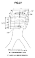
- the VOI setting function section 13 a sets a VOI start section having a section 101 of a tubular organ on the basis of the sectional shape of the tubular organ as shown in FIG. 27 for instance.
- the VOI setting function section 13 a calculates the gravity center and the radius r of a section of a tubular organ in the VOI start section on the basis of the sectional shape of the tubular organ, and further the VOI setting function section 13 a calculates at step 12 d a normal line vector 750 (see FIG. 27 ) in the direction of the body axis (the axial direction from head to feet) in the section of the tubular organ.
- the VOI setting function section 13 a sets the VOI 102 (see FIG. 27 ) as a volume area having on its top face the section 101 of the tubular organ on the basis of the sectional shape of the tubular organ.
- the VOI setting function section 13 a calculates an extension quantity ⁇ t of extension in the direction of the normal line vector 750 .
- the VOI setting function section 13 a stores and registers the coordinates of the VOI start section, the normal line vector 750 and the extension quantity ⁇ t into the storage section (not shown) within the organ area extracting section 14 to complete the processing.
- FIG. 28 shows a section of the VOI 102 obtained by slicing the tubular organ shown in FIG. 27 along a plane normal to the VOI start section and parallel to the body axis
- the VOI size determining function section 13 g determines at step S 17 that the size of the VOI 102 has surpassed a prescribed size. At the step S 17 , the VOI size determining function section 13 g further determines whether or not a difference ⁇ r between the position of the gravity center of the section of the tubular organ on the extended side end face of the extended VOI 102 and the intersection point where the normal line vector 750 crosses on the extended side end face has surpassed a prescribed value L.
- the processing returns to step S 12 , the VOI setting function section 13 a links the position of the gravity center of the section of the tubular organ on the extended side end face of the finally extended VOI 102 and the position of the gravity center of the section of the tubular organ on the extended side end face of the VOI 102 one extension step before, and sets a new normal line vector 750 ′ (see FIG. 29 ) headed in the direction of the body axis (the axial direction from head to feet). Then the VOI setting function section 13 a sets as the VOI start section a section of the tubular organ on the extended side end face of the finally extended VOI 102 having a point of orthogonally crossing the normal line vector 750 ′.
- the VOI setting function section 13 a sets at step S 12 a new VOI 102 ′ (see FIG. 29 ) as a lower layer volume area having a new VOI start section.
- the VOI setting function section 13 a corrects the gap so as to keep the continuity of the tubular path area information and sets a new VOI 102 ′ (see FIG. 30 ).
- tubular path area information consumed a very long time as the extension quantity was set pixel by pixel, but the processing to arrange and register a new VOI as described above sets the extension quantity ⁇ t to the radius r of the section of the tubular organ in the VOI start section, which is greater than the conventional pixel-by-pixel extension quantity, enabling tubular path area information to be obtained at high speed.
- the time taken to acquire tubular path area information on the whole bronchial area can be reduced to 1 ⁇ 6 for instance.
- step S 21 the processing to extract the branching point at step S 21 of FIG. 8 will be described with reference to FIG. 31 and FIG. 32 .
- step S 16 if it is determined that the branching point is surpassed (step S 16 ) and the bronchial periphery is not reached (step S 20 ), the processing to extract the branching point at step S 21 is executed.
- the processing to extract a branching point in the present embodiment enables the extended side section of the VOI 102 to be converged onto the position of the branching point at high speed by a simple procedure.
- the organ area extracting section 14 extracts the shape of the extended side section of the VOI 102 , and determines whether or not there is a strictured part 1000 , for instance, on the extended side section of the VOI 102 .
- the extended side section of the VOI 102 is substantially circular as shown in FIG. 34 .
- the extended side section of the VOI 102 is a deformed circle as shown in FIG. 35 .
- the extended side section of the VOI 102 manifests a shape which cannot be regarded as a circle as shown in FIG. 36 .
- the organ area extracting section 14 constituting the heteromorphic state detecting section stores into the storage section (not shown) within the organ area extracting section 14 the strictured part information as information indicating the heteromorphic state of the sectional shape of the bronchus.
- the organ area extracting section 14 stores into the storage section (not shown) within the organ area extracting section 14 the extended side section as strictured part information if the difference between a longer axis length a and a shorter axis length b of the extended side section is greater than a prescribed difference.
- the organ area extracting section 14 which is the heteromorphic state detecting section stores information indicating the heteromorphic state into the storage section (not shown) within the organ area extracting section 14 .
- the VOI extending function section 13 b extracts tubular path area information on the second layer second bronchial tree 100 ( 2 ) while extending the VOI 102 ( 2 )
- a flank of the second layer second bronchial tree 100 ( 2 ) comes into contact with the VOI 102 ( 2 ) as shown in FIG. 40 as a result of extending the VOI 102 ( 2 )
- the VOI direction determining function section 13 c determines the direction of the VOI to be inappropriate in the processing to determine the direction at step S 16 .
- the VOI generation setting section 13 would correct the direction of the VOI 102 ( 2 ) so as to let the second layer second bronchial tree 100 ( 2 ) enter the VOI 102 ( 2 ) at step S 32 as shown in FIG. 41 .
- the second layer second bronchial tree 100 ( 2 ) cannot be accommodated into the VOI 102 ( 2 ) as shown in FIG. 42 .
- step S 33 determines at step S 33 that the second layer second bronchial tree 100 ( 2 ) can be accommodated into the VOI 102 ( 2 )
- step S 19 extends the VOI 102 ( 2 ) at step S 19 , and returns to step S 14 to repeat the processing.
- the VOI generation setting section 13 determines at step S 32 that the second layer second bronchial tree 100 ( 2 ) cannot be accommodated into the VOI 102 ( 2 ), it advances to step S 22 and shifts to determination of the completion of extraction. Then if at step S 22 the VOI generation setting section 13 and the organ area extracting section 14 determine that the extraction of the whole bronchus has been completed, they complete the processing after step S 23 or, if they determine that the extraction of the whole bronchial tree has not been completed, they return to step S 13 to repeat the processing.
- a new VOI 102 ( 2 b ) to be linked to the VOI 102 ( 2 a ) is arranged in the second layer second bronchial tree 100 ( 2 b ) of the second level in the present embodiment as shown in FIG. 26 , and the organ area extracting section 14 extracts tubular path area information by using the VOI 102 ( 2 b ). Therefore, the present embodiment can securely extract all the consecutive bronchial trees.
- step S 23 in the processing of judgment on extraction area expansion at step S 23 in FIG. 8 , where a third layer second bronchial tree 100 ( 22 ) is not a periphery but is blocked as shown in FIG. 43 for instance, there further is a bronchial tree 200 beyond the blocked end of the third layer second bronchial tree 100 ( 22 ). Then at step S 23 the VOI resetting function section 13 e confirms according to the user's judgment whether or not the extraction area is to be expanded to the unextracted bronchial tree 200 beyond the blocked end. When the VOI resetting function section 13 e confirms the extraction area of the bronchus 200 beyond the blocked end, the processing returns to step S 11 .
- step S 11 the setting information input section 20 designates a start point in the bronchus 200 beyond the blocked end with the instruction of the user, and a start point marker 27 a is set.
- a start point marker 27 a is set.
- the processing at and after step S 13 subjects the bronchus 200 beyond the blocked end to extraction processing.
- start point may as well be set at the periphery of the bronchus as shown in FIG. 46 , instead of the proximal end side of the bronchus, to have the VOI arranged and registered from the peripheral side toward the upper part of the body axis to perform extraction processing on the bronchus 200 .
- a VOI is arranged and registered for every bronchial tree from the start point to the periphery, and a VOI core, which is the approximate center line, is registered with every VOI 102 .
- the route setting section 15 sets the route 52 from the support start point 51 , set by the setting information input section 20 , to the target 500 , which is the support end point, on the bronchus 50 displayed on the monitor 5 at step S 7 in FIG. 3 .
- a VOI having a VOI core on which the target 500 is located is selected.
- a VOI 102 ( 211 ) is selected as the target VOI
- a plurality of VOIs having VOI cores at the nearest distance ⁇ D to the target 500 are selected as the target VOI.
- the VOI 102 ( 211 ) is selected, and a VOI 102 ( 21 ), a VOI 102 ( 2 ) and a VOI 102 linked successively to the VOI 102 ( 211 ) are automatically extracted, and VOI cores 110 ( 211 ), 110 ( 21 ), 110 ( 2 ) and 110 of these VOI 102 ( 211 ), VOI 102 ( 21 ), VOI 102 ( 2 ) and VOI 102 are set by the route setting section 15 as the route 52 from the support start point 51 to the target 500 , which is the support end point.
- a plurality of VOIs having VOI cores at the nearest distance ⁇ D to the target 500 are selected.
- the VOI 102 ( 212 ) is selected as the target VOI, and a VOI 102 ( 21 ), a VOI 102 ( 2 ) and a VOI 102 linked successively to this VOI 102 ( 212 ) are automatically extracted.
- first a VOI 102 ( 221 ) is selected as the target VOI, and a VOI 102 ( 22 ), a VOI 102 ( 2 ) and a VOI 102 linked successively to the VOI 102 ( 221 ) are automatically extracted.
- the route setting section 15 sets the one shorter in the distance of the cores linked from the support start point 51 to the target 500 , which is the support end point, as the route 52 .
- the VOI cores 110 ( 212 ), 110 ( 21 ), 110 ( 2 ) and 110 of the VOI 102 ( 212 ), VOI 102 ( 21 ), VOI 102 ( 2 ) and VOI 102 of FIG. 49 which are shorter in the distance of the linked cores, are selected by the route setting section 15 as the route 52 from the support start point 51 to the target 500 , which is the support end point.
- the route setting section 15 after setting the cores linked from the support start point 51 to the target 500 , which is the support end point, as the route 52 as described above, executes spline interpolation processing so as to be suitable for observation as shown in FIG. 51 for fine adjustment of each point, correct the route into a smooth curve 600 and, as shown in FIG. 52 , sets this curve 600 as the route 52 .
- an insertion support screen 151 as shown in FIG. 53 is displayed on the monitor 5 .
- the insertion support screen 151 comprises a live endoscopic image display area 152 for displaying a live image 152 a from the bronchoscope apparatus 2 , a VBS image display area 153 for displaying a VBS image 153 a , and branch thumbnail VBS image areas 154 for displaying branch thumbnail VBS images 154 ( a ) through 154 ( j ) obtained by compressing VBS images 153 a at all the branching points on the route; the VBS image 153 a of the first branching point on the route is displayed on the VBS image display area 153 , and the branch thumbnail VBS images 154 ( a ) through 154 ( j ) at all the branching points are displayed on the branch thumbnail VBS image areas 154 .
- a navi-marker 155 is displayed on the VBS image 153 a superposed over a route hole leading to the route.
- the frame of the same branch thumbnail VBS image as the VBS image 153 a displayed in the VBS image display area 153 is displayed in bold lines or in color to make it distinguishable from other thumbnail VBS images, and the operator can readily distinguish it from any other branch thumbnail VBS image.
- the frame of the branch thumbnail VBS image 154 ( a ) is displayed in bold lines or in color.
- a new VOI is set for each branching point after the setting of the root VOI, and a new VOI is also set when it is determined that VOI extension processing has made VOI unable to accommodate any more bronchial tree.
- sectional information on the strictured part is eliminated or corrected to set a new VOI in an appropriate size, and at the same time a new VOI can be set in an appropriate size beyond a blocked bronchial tree.
- tubular path area information can be surely extracted from every bronchial tree at least without affecting by any strictured part.
- route setting can be accomplished easily and at high speed.
- a VOI is supposed to be shaped as a quadrangular prism in the foregoing description, this is not the only usable shape, but it may be columnar-shaped as shown in FIG. 54 or shaped as a multi-angled pillar whose sectional shape can contain sections of the bronchus in its upper and lower planes.
- the bronchoscope insertion support system 1 is referred to as the body cavity insertion support system in describing the present embodiment
- the present embodiment can be applied to a large intestinal insertion support system or the like, which supports insertion into a complexly bent body cavity organ such as the large intestine, enabling VOI to be appropriately set.
- the present embodiment can obviously be applied not only to the bronchus or the large intestine but also to any body cavity organ having a tree structure, such as the blood vessel, small intestine, bile duct, pancreatic duct or lymphatic vessel.
- a tubular path insertion support system can obtain tubular path area information at high speed because the processing of new VOI arrangement and registration described above uses the radius r of the section of the tubular organ in the VOI start section as the quantity of extension ⁇ t, which is larger than the conventional pixel-by-pixel quantity of extension (supporting drawings: FIG. 27 through FIG. 30 ).
- the processing to extract a branching point in a tubular path insertion system enables the extended side section of the VOI 102 to be converged onto the position of the branching point at high speed by a simple procedure (supporting drawings: FIG. 31 and FIG. 32 ).
- the present invention is not limited to the present embodiment described above, but can be altered or modified in various ways without deviating from the essentials of the invention.
Abstract
Description
Claims (12)
Applications Claiming Priority (3)
| Application Number | Priority Date | Filing Date | Title |
|---|---|---|---|
| JP2006128682 | 2006-05-02 | ||
| JP2006-128682 | 2006-05-02 | ||
| PCT/JP2007/059208 WO2007129616A1 (en) | 2006-05-02 | 2007-04-27 | Insertion assist system of endoscope and insertion assist method of endoscope |
Related Parent Applications (1)
| Application Number | Title | Priority Date | Filing Date |
|---|---|---|---|
| PCT/JP2007/059208 Continuation WO2007129616A1 (en) | 2006-05-02 | 2007-04-27 | Insertion assist system of endoscope and insertion assist method of endoscope |
Publications (2)
| Publication Number | Publication Date |
|---|---|
| US20090054729A1 US20090054729A1 (en) | 2009-02-26 |
| US8509877B2 true US8509877B2 (en) | 2013-08-13 |
Family
ID=38667725
Family Applications (1)
| Application Number | Title | Priority Date | Filing Date |
|---|---|---|---|
| US12/260,630 Active 2030-10-15 US8509877B2 (en) | 2006-05-02 | 2008-10-29 | Endoscope insertion support system and endoscope insertion support method |
Country Status (3)
| Country | Link |
|---|---|
| US (1) | US8509877B2 (en) |
| JP (1) | JP4822142B2 (en) |
| WO (1) | WO2007129616A1 (en) |
Cited By (12)
| Publication number | Priority date | Publication date | Assignee | Title |
|---|---|---|---|---|
| US20140101639A1 (en) * | 2009-07-01 | 2014-04-10 | International Business Machines Corporation | Serializing a templated markup language representation of test artifacts |
| US9530219B2 (en) | 2014-07-02 | 2016-12-27 | Covidien Lp | System and method for detecting trachea |
| US9603668B2 (en) | 2014-07-02 | 2017-03-28 | Covidien Lp | Dynamic 3D lung map view for tool navigation inside the lung |
| US9754367B2 (en) | 2014-07-02 | 2017-09-05 | Covidien Lp | Trachea marking |
| US9770216B2 (en) | 2014-07-02 | 2017-09-26 | Covidien Lp | System and method for navigating within the lung |
| US9836848B2 (en) | 2014-07-02 | 2017-12-05 | Covidien Lp | System and method for segmentation of lung |
| US10643371B2 (en) | 2014-08-11 | 2020-05-05 | Covidien Lp | Treatment procedure planning system and method |
| US10709352B2 (en) | 2015-10-27 | 2020-07-14 | Covidien Lp | Method of using lung airway carina locations to improve ENB registration |
| US10772532B2 (en) | 2014-07-02 | 2020-09-15 | Covidien Lp | Real-time automatic registration feedback |
| USD916749S1 (en) | 2014-07-02 | 2021-04-20 | Covidien Lp | Display screen or portion thereof with graphical user interface |
| US10986990B2 (en) | 2015-09-24 | 2021-04-27 | Covidien Lp | Marker placement |
| US11224392B2 (en) | 2018-02-01 | 2022-01-18 | Covidien Lp | Mapping disease spread |
Families Citing this family (43)
| Publication number | Priority date | Publication date | Assignee | Title |
|---|---|---|---|---|
| JP5173718B2 (en) * | 2008-09-30 | 2013-04-03 | 株式会社東芝 | X-ray equipment |
| WO2010055815A1 (en) * | 2008-11-13 | 2010-05-20 | 株式会社 日立メディコ | Medical image-processing device and method |
| JP5715064B2 (en) * | 2008-12-10 | 2015-05-07 | コーニンクレッカ フィリップス エヌ ヴェ | Blood vessel analysis |
| US8672837B2 (en) | 2010-06-24 | 2014-03-18 | Hansen Medical, Inc. | Methods and devices for controlling a shapeable medical device |
| JP5932406B2 (en) * | 2012-03-09 | 2016-06-08 | 富士フイルム株式会社 | Medical image processing apparatus and method, and program |
| US10039473B2 (en) | 2012-05-14 | 2018-08-07 | Intuitive Surgical Operations, Inc. | Systems and methods for navigation based on ordered sensor records |
| EP3524184B1 (en) | 2012-05-14 | 2021-02-24 | Intuitive Surgical Operations Inc. | Systems for registration of a medical device using a reduced search space |
| KR102301021B1 (en) | 2012-08-14 | 2021-09-13 | 인튜어티브 서지컬 오퍼레이션즈 인코포레이티드 | Systems and methods for registration of multiple vision systems |
| JP5930539B2 (en) | 2012-09-12 | 2016-06-08 | 富士フイルム株式会社 | MEDICAL IMAGE DISPLAY DEVICE, METHOD, AND PROGRAM |
| JP6139090B2 (en) * | 2012-10-09 | 2017-05-31 | 東芝メディカルシステムズ株式会社 | Medical image processing apparatus, image diagnostic apparatus, and medical image processing program |
| CN104736085B (en) | 2012-10-12 | 2018-01-30 | 直观外科手术操作公司 | Determine position of the medicine equipment in branch's anatomical structure |
| KR102087595B1 (en) * | 2013-02-28 | 2020-03-12 | 삼성전자주식회사 | Endoscope system and control method thereof |
| US9057600B2 (en) | 2013-03-13 | 2015-06-16 | Hansen Medical, Inc. | Reducing incremental measurement sensor error |
| US9271663B2 (en) | 2013-03-15 | 2016-03-01 | Hansen Medical, Inc. | Flexible instrument localization from both remote and elongation sensors |
| US9014851B2 (en) | 2013-03-15 | 2015-04-21 | Hansen Medical, Inc. | Systems and methods for tracking robotically controlled medical instruments |
| US9629595B2 (en) | 2013-03-15 | 2017-04-25 | Hansen Medical, Inc. | Systems and methods for localizing, tracking and/or controlling medical instruments |
| US11020016B2 (en) | 2013-05-30 | 2021-06-01 | Auris Health, Inc. | System and method for displaying anatomy and devices on a movable display |
| JP6824967B2 (en) | 2015-09-18 | 2021-02-03 | オーリス ヘルス インコーポレイテッド | Tubular net navigation |
| JP2017074320A (en) * | 2015-10-16 | 2017-04-20 | キヤノンマーケティングジャパン株式会社 | Medical image processing device, program mountable on medical image processing device, and medical image processing method |
| US10143526B2 (en) | 2015-11-30 | 2018-12-04 | Auris Health, Inc. | Robot-assisted driving systems and methods |
| JP6780936B2 (en) * | 2016-01-13 | 2020-11-04 | ザイオソフト株式会社 | Medical image processing equipment, medical image processing methods, and medical image processing programs |
| US20200320684A1 (en) * | 2016-06-16 | 2020-10-08 | Koninklijke Philips N.V. | A method and apparatus for mapping at least part of a structure in an image of at least part of a body of a subject |
| US10244926B2 (en) | 2016-12-28 | 2019-04-02 | Auris Health, Inc. | Detecting endolumenal buckling of flexible instruments |
| JP6702902B2 (en) * | 2017-02-24 | 2020-06-03 | 富士フイルム株式会社 | Mapping image display control device, method and program |
| WO2018183727A1 (en) | 2017-03-31 | 2018-10-04 | Auris Health, Inc. | Robotic systems for navigation of luminal networks that compensate for physiological noise |
| CN110769731B (en) * | 2017-06-15 | 2022-02-25 | 奥林巴斯株式会社 | Endoscope system, processing system for endoscope, and image processing method |
| US10022192B1 (en) | 2017-06-23 | 2018-07-17 | Auris Health, Inc. | Automatically-initialized robotic systems for navigation of luminal networks |
| US10555778B2 (en) | 2017-10-13 | 2020-02-11 | Auris Health, Inc. | Image-based branch detection and mapping for navigation |
| US11058493B2 (en) | 2017-10-13 | 2021-07-13 | Auris Health, Inc. | Robotic system configured for navigation path tracing |
| JP7322026B2 (en) | 2017-12-14 | 2023-08-07 | オーリス ヘルス インコーポレイテッド | System and method for instrument localization |
| WO2019125964A1 (en) | 2017-12-18 | 2019-06-27 | Auris Health, Inc. | Methods and systems for instrument tracking and navigation within luminal networks |
| CN110891469B (en) | 2018-03-28 | 2023-01-13 | 奥瑞斯健康公司 | System and method for registration of positioning sensors |
| US10827913B2 (en) | 2018-03-28 | 2020-11-10 | Auris Health, Inc. | Systems and methods for displaying estimated location of instrument |
| CN114601559A (en) | 2018-05-30 | 2022-06-10 | 奥瑞斯健康公司 | System and medium for location sensor based branch prediction |
| MX2020012904A (en) | 2018-05-31 | 2021-02-26 | Auris Health Inc | Image-based airway analysis and mapping. |
| EP3801189A4 (en) | 2018-05-31 | 2022-02-23 | Auris Health, Inc. | Path-based navigation of tubular networks |
| CN112236083A (en) | 2018-05-31 | 2021-01-15 | 奥瑞斯健康公司 | Robotic system and method for navigating a luminal network detecting physiological noise |
| CN109448633B (en) * | 2019-01-07 | 2020-12-08 | 卡莱特(深圳)云科技有限公司 | Special-shaped LED display screen display implementation control method and implementation system |
| JP2022546421A (en) | 2019-08-30 | 2022-11-04 | オーリス ヘルス インコーポレイテッド | Systems and methods for weight-based registration of position sensors |
| WO2021038495A1 (en) | 2019-08-30 | 2021-03-04 | Auris Health, Inc. | Instrument image reliability systems and methods |
| CN114929148A (en) | 2019-12-31 | 2022-08-19 | 奥瑞斯健康公司 | Alignment interface for percutaneous access |
| EP4084721A4 (en) | 2019-12-31 | 2024-01-03 | Auris Health Inc | Anatomical feature identification and targeting |
| EP4084720A4 (en) | 2019-12-31 | 2024-01-17 | Auris Health Inc | Alignment techniques for percutaneous access |
Citations (5)
| Publication number | Priority date | Publication date | Assignee | Title |
|---|---|---|---|---|
| JP2000135215A (en) | 1998-10-30 | 2000-05-16 | Ge Yokogawa Medical Systems Ltd | Conduit guiding method and device thereof and radiation tomographic equipment |
| US6343936B1 (en) * | 1996-09-16 | 2002-02-05 | The Research Foundation Of State University Of New York | System and method for performing a three-dimensional virtual examination, navigation and visualization |
| US20040220466A1 (en) | 2003-04-02 | 2004-11-04 | Kazuhiko Matsumoto | Medical image processing apparatus, and medical image processing method |
| JP2004313736A (en) | 2003-04-02 | 2004-11-11 | Ziosoft Inc | Apparatus, method and program for medical image processing |
| JP2004350791A (en) | 2003-05-27 | 2004-12-16 | Aloka Co Ltd | Ultrasonic image processor and three-dimensional data processing method |
-
2007
- 2007-04-27 WO PCT/JP2007/059208 patent/WO2007129616A1/en active Application Filing
- 2007-04-27 JP JP2008514452A patent/JP4822142B2/en active Active
-
2008
- 2008-10-29 US US12/260,630 patent/US8509877B2/en active Active
Patent Citations (5)
| Publication number | Priority date | Publication date | Assignee | Title |
|---|---|---|---|---|
| US6343936B1 (en) * | 1996-09-16 | 2002-02-05 | The Research Foundation Of State University Of New York | System and method for performing a three-dimensional virtual examination, navigation and visualization |
| JP2000135215A (en) | 1998-10-30 | 2000-05-16 | Ge Yokogawa Medical Systems Ltd | Conduit guiding method and device thereof and radiation tomographic equipment |
| US20040220466A1 (en) | 2003-04-02 | 2004-11-04 | Kazuhiko Matsumoto | Medical image processing apparatus, and medical image processing method |
| JP2004313736A (en) | 2003-04-02 | 2004-11-11 | Ziosoft Inc | Apparatus, method and program for medical image processing |
| JP2004350791A (en) | 2003-05-27 | 2004-12-16 | Aloka Co Ltd | Ultrasonic image processor and three-dimensional data processing method |
Non-Patent Citations (1)
| Title |
|---|
| Kitasaka, T. et al., "A Method for Extraction of Bronchus Regions from 3D Chest X-ray CT Images by Analyzing Structural Features of the Bronchus", Forma, (2002), pp. 321-338, vol. 17, No. 4. |
Cited By (44)
| Publication number | Priority date | Publication date | Assignee | Title |
|---|---|---|---|---|
| US20140101639A1 (en) * | 2009-07-01 | 2014-04-10 | International Business Machines Corporation | Serializing a templated markup language representation of test artifacts |
| US9032364B2 (en) * | 2009-07-01 | 2015-05-12 | International Business Machines Corporation | Serializing a templated markup language representation of test artifacts |
| US10799297B2 (en) | 2014-07-02 | 2020-10-13 | Covidien Lp | Dynamic 3D lung map view for tool navigation inside the lung |
| US9848953B2 (en) | 2014-07-02 | 2017-12-26 | Covidien Lp | Dynamic 3D lung map view for tool navigation inside the lung |
| USD916749S1 (en) | 2014-07-02 | 2021-04-20 | Covidien Lp | Display screen or portion thereof with graphical user interface |
| US9741115B2 (en) | 2014-07-02 | 2017-08-22 | Covidien Lp | System and method for detecting trachea |
| US9754367B2 (en) | 2014-07-02 | 2017-09-05 | Covidien Lp | Trachea marking |
| US9770216B2 (en) | 2014-07-02 | 2017-09-26 | Covidien Lp | System and method for navigating within the lung |
| US9836848B2 (en) | 2014-07-02 | 2017-12-05 | Covidien Lp | System and method for segmentation of lung |
| US10878573B2 (en) | 2014-07-02 | 2020-12-29 | Covidien Lp | System and method for segmentation of lung |
| US9990721B2 (en) | 2014-07-02 | 2018-06-05 | Covidien Lp | System and method for detecting trachea |
| US10062166B2 (en) | 2014-07-02 | 2018-08-28 | Covidien Lp | Trachea marking |
| US10074185B2 (en) | 2014-07-02 | 2018-09-11 | Covidien Lp | System and method for segmentation of lung |
| US10105185B2 (en) | 2014-07-02 | 2018-10-23 | Covidien Lp | Dynamic 3D lung map view for tool navigation |
| US9530219B2 (en) | 2014-07-02 | 2016-12-27 | Covidien Lp | System and method for detecting trachea |
| US11877804B2 (en) | 2014-07-02 | 2024-01-23 | Covidien Lp | Methods for navigation of catheters inside lungs |
| US10646277B2 (en) | 2014-07-02 | 2020-05-12 | Covidien Lp | Methods of providing a map view of a lung or luminal network using a 3D model |
| US10653485B2 (en) | 2014-07-02 | 2020-05-19 | Covidien Lp | System and method of intraluminal navigation using a 3D model |
| US10660708B2 (en) | 2014-07-02 | 2020-05-26 | Covidien Lp | Dynamic 3D lung map view for tool navigation inside the lung |
| US11823431B2 (en) | 2014-07-02 | 2023-11-21 | Covidien Lp | System and method for detecting trachea |
| US10772532B2 (en) | 2014-07-02 | 2020-09-15 | Covidien Lp | Real-time automatic registration feedback |
| US10776914B2 (en) | 2014-07-02 | 2020-09-15 | Covidien Lp | System and method for detecting trachea |
| US10460441B2 (en) | 2014-07-02 | 2019-10-29 | Covidien Lp | Trachea marking |
| US9603668B2 (en) | 2014-07-02 | 2017-03-28 | Covidien Lp | Dynamic 3D lung map view for tool navigation inside the lung |
| US9607395B2 (en) | 2014-07-02 | 2017-03-28 | Covidien Lp | System and method for detecting trachea |
| USD916750S1 (en) | 2014-07-02 | 2021-04-20 | Covidien Lp | Display screen or portion thereof with graphical user interface |
| US11607276B2 (en) | 2014-07-02 | 2023-03-21 | Covidien Lp | Dynamic 3D lung map view for tool navigation inside the lung |
| US11026644B2 (en) | 2014-07-02 | 2021-06-08 | Covidien Lp | System and method for navigating within the lung |
| US11172989B2 (en) | 2014-07-02 | 2021-11-16 | Covidien Lp | Dynamic 3D lung map view for tool navigation inside the lung |
| US11583205B2 (en) | 2014-07-02 | 2023-02-21 | Covidien Lp | Real-time automatic registration feedback |
| US11576556B2 (en) | 2014-07-02 | 2023-02-14 | Covidien Lp | System and method for navigating within the lung |
| US11547485B2 (en) | 2014-07-02 | 2023-01-10 | Covidien Lp | Dynamic 3D lung map view for tool navigation inside the lung |
| US11361439B2 (en) | 2014-07-02 | 2022-06-14 | Covidien Lp | System and method for detecting trachea |
| US11389247B2 (en) | 2014-07-02 | 2022-07-19 | Covidien Lp | Methods for navigation of a probe inside a lung |
| US11529192B2 (en) | 2014-07-02 | 2022-12-20 | Covidien Lp | Dynamic 3D lung map view for tool navigation inside the lung |
| US11238642B2 (en) | 2014-08-11 | 2022-02-01 | Covidien Lp | Treatment procedure planning system and method |
| US11227427B2 (en) | 2014-08-11 | 2022-01-18 | Covidien Lp | Treatment procedure planning system and method |
| US11769292B2 (en) | 2014-08-11 | 2023-09-26 | Covidien Lp | Treatment procedure planning system and method |
| US10643371B2 (en) | 2014-08-11 | 2020-05-05 | Covidien Lp | Treatment procedure planning system and method |
| US10986990B2 (en) | 2015-09-24 | 2021-04-27 | Covidien Lp | Marker placement |
| US11672415B2 (en) | 2015-09-24 | 2023-06-13 | Covidien Lp | Marker placement |
| US11576588B2 (en) | 2015-10-27 | 2023-02-14 | Covidien Lp | Method of using lung airway carina locations to improve ENB registration |
| US10709352B2 (en) | 2015-10-27 | 2020-07-14 | Covidien Lp | Method of using lung airway carina locations to improve ENB registration |
| US11224392B2 (en) | 2018-02-01 | 2022-01-18 | Covidien Lp | Mapping disease spread |
Also Published As
| Publication number | Publication date |
|---|---|
| WO2007129616A1 (en) | 2007-11-15 |
| JP4822142B2 (en) | 2011-11-24 |
| US20090054729A1 (en) | 2009-02-26 |
| JPWO2007129616A1 (en) | 2009-09-17 |
Similar Documents
| Publication | Publication Date | Title |
|---|---|---|
| US8509877B2 (en) | Endoscope insertion support system and endoscope insertion support method | |
| EP1685787B1 (en) | Insertion support system | |
| US8049777B2 (en) | Insertion support system for specifying a location of interest as an arbitrary region and also appropriately setting a navigation leading to the specified region | |
| US7929014B2 (en) | Insertion support system | |
| JP4676021B2 (en) | Diagnosis support apparatus, diagnosis support program, and diagnosis support method | |
| JP5918548B2 (en) | Endoscopic image diagnosis support apparatus, operation method thereof, and endoscopic image diagnosis support program | |
| US20050261550A1 (en) | System, apparatus, and method for supporting insertion of endoscope | |
| JP5028191B2 (en) | Endoscope device | |
| JP4922107B2 (en) | Endoscope device | |
| JP6254053B2 (en) | Endoscopic image diagnosis support apparatus, system and program, and operation method of endoscopic image diagnosis support apparatus | |
| JP2006246941A (en) | Image processing apparatus and vessel tracking method | |
| JPWO2007129493A1 (en) | Medical image observation support device | |
| JP4323288B2 (en) | Insertion support system | |
| JP4022192B2 (en) | Insertion support system | |
| JP4445792B2 (en) | Insertion support system | |
| JP2009056143A (en) | Endoscope insertion support device | |
| US11056149B2 (en) | Medical image storage and reproduction apparatus, method, and program | |
| JP4546064B2 (en) | Insertion simulation device | |
| JP4190454B2 (en) | Insertion support device | |
| JP4354353B2 (en) | Insertion support system | |
| WO2024009132A1 (en) | Enhancing endoscopic ultrasound procedures with tracking and visual intelligence |
Legal Events
| Date | Code | Title | Description |
|---|---|---|---|
| AS | Assignment |
Owner name: OLYMPUS MEDICAL SYSTEMS CORP., JAPAN Free format text: ASSIGNMENT OF ASSIGNORS INTEREST;ASSIGNORS:MORI, KENSAKU;KITASAKA, TAKAYUKI;AKIMOTO, SHUNYA;AND OTHERS;REEL/FRAME:021757/0497;SIGNING DATES FROM 20080912 TO 20080930 Owner name: OLYMPUS MEDICAL SYSTEMS CORP., JAPAN Free format text: ASSIGNMENT OF ASSIGNORS INTEREST;ASSIGNORS:MORI, KENSAKU;KITASAKA, TAKAYUKI;AKIMOTO, SHUNYA;AND OTHERS;SIGNING DATES FROM 20080912 TO 20080930;REEL/FRAME:021757/0497 |
|
| STCF | Information on status: patent grant |
Free format text: PATENTED CASE |
|
| AS | Assignment |
Owner name: OLYMPUS CORPORATION, JAPAN Free format text: ASSIGNMENT OF ASSIGNORS INTEREST;ASSIGNOR:OLYMPUS MEDICAL SYSTEMS CORP.;REEL/FRAME:036276/0543 Effective date: 20150401 |
|
| AS | Assignment |
Owner name: OLYMPUS CORPORATION, JAPAN Free format text: CHANGE OF ADDRESS;ASSIGNOR:OLYMPUS CORPORATION;REEL/FRAME:039344/0502 Effective date: 20160401 |
|
| FPAY | Fee payment |
Year of fee payment: 4 |
|
| MAFP | Maintenance fee payment |
Free format text: PAYMENT OF MAINTENANCE FEE, 8TH YEAR, LARGE ENTITY (ORIGINAL EVENT CODE: M1552); ENTITY STATUS OF PATENT OWNER: LARGE ENTITY Year of fee payment: 8 |