US6097394A - Method and system for light field rendering - Google Patents
Method and system for light field rendering Download PDFInfo
- Publication number
- US6097394A US6097394A US08/848,569 US84856997A US6097394A US 6097394 A US6097394 A US 6097394A US 84856997 A US84856997 A US 84856997A US 6097394 A US6097394 A US 6097394A
- Authority
- US
- United States
- Prior art keywords
- radiance
- light
- light field
- data
- images
- Prior art date
- Legal status (The legal status is an assumption and is not a legal conclusion. Google has not performed a legal analysis and makes no representation as to the accuracy of the status listed.)
- Expired - Lifetime
Links
Images


Classifications
-
- G—PHYSICS
- G06—COMPUTING; CALCULATING OR COUNTING
- G06T—IMAGE DATA PROCESSING OR GENERATION, IN GENERAL
- G06T17/00—Three dimensional [3D] modelling, e.g. data description of 3D objects
-
- G—PHYSICS
- G02—OPTICS
- G02B—OPTICAL ELEMENTS, SYSTEMS OR APPARATUS
- G02B30/00—Optical systems or apparatus for producing three-dimensional [3D] effects, e.g. stereoscopic images
- G02B30/50—Optical systems or apparatus for producing three-dimensional [3D] effects, e.g. stereoscopic images the image being built up from image elements distributed over a 3D volume, e.g. voxels
-
- H—ELECTRICITY
- H04—ELECTRIC COMMUNICATION TECHNIQUE
- H04N—PICTORIAL COMMUNICATION, e.g. TELEVISION
- H04N13/00—Stereoscopic video systems; Multi-view video systems; Details thereof
- H04N13/20—Image signal generators
- H04N13/204—Image signal generators using stereoscopic image cameras
- H04N13/207—Image signal generators using stereoscopic image cameras using a single 2D image sensor
- H04N13/232—Image signal generators using stereoscopic image cameras using a single 2D image sensor using fly-eye lenses, e.g. arrangements of circular lenses
Definitions
- the present invention relates to the field of graphical imaging. More particularly, it relates to a system and method for generating new views of a three-dimensional scene from arbitrary positions without depth information or feature matching, by combining and resampling the available images.
- the input to a three-dimensional graphics system is a scene consisting of geometric primitives composed of different materials and a set of lights. Based on this input specification, the rendering system computes and outputs an image. Recently, a new approach to rendering has emerged which is known as image-based rendering. Image-based rendering systems generate different views of an environment from a set of pre-acquired imagery.
- the display algorithms for image-based rendering require modest computational resources and are thus suitable for real-time implementation on workstations and personal computers.
- the cost of interactively viewing the scene is independent of the scene complexity. Even with the best algorithms and fastest hardware, it often takes minutes or hours using existing systems to generate images with the visual richness required for many applications.
- the source of the pre-acquired images can be from a real or virtual environment (i.e. from digitized photographs or from rendered models), or from a combination of the two.
- environment maps to capture the incoming light in a texture map. See, e.g., J. F. Blinn & M. E. Newell, "Texture and Reflection in Computer Generated Images," CACM, Vol. 19, No. 10, October 1976, pp. 542-47; N. Greene, "Environment Mapping and Other Applications of World Projections," IEEE Computer Graphics and Applications, Vol. 6, No. 11, November 1986, pp. 21-29.
- An environment map records the incident light arriving from all directions at a point. The original use of environmental maps was to efficiently approximate reflections of the environment on a surface. However, environment maps also may be used to quickly display any outward looking view of the environment from a fixed location but at a variable orientation.
- An abstract representation of light that is related to the present invention is epipolar volumes. See R. Bolles et al, "Epipolar-Plane Image Analysis: An Approach to Determining Structure from Motion," International Journal of Computer Vision, Vol. 1, No. 1, 1987, pp. 7-55.
- An epipolar volume is formed of an array of images created by translating a camera in equal increments in a single direction. Such a representation has been used recently to perform view interpolation.
- Katayama et al. "Viewpoint-Dependent Stereoscopic Display Using Interpolation of Multiviewpoint Images," Stereoscopic Displays and Virtual Reality Systems II, Proc. SPIE, Vol. 2409, S. Fisher, J. Merrit, B. Bolas eds. 1995, pp. 11-20.
- the primary object of this invention is to provide a technique for displaying three dimensional scenes from previously acquired imagery.
- a term commonly applied to such techniques is image-based rendering.
- our technique utilizes a representation of the "light field,” a term used herein to denote the radiance as a function of position and direction in regions of space free of occluders ("free space").
- the light field is a four-dimensional, rather than a five-dimensional function.
- An image is a two-dimensional slice of the four-dimensional light field. Creating a light field from a set of images corresponds to inserting each two-dimensional slice into the four-dimensional light field representation. Similarly, generating new views corresponds to extracting and resampling a slice.
- the new image is generally formed from many different pieces of the original input images, and need not look like any of them.
- no model information such as depth values or image correspondences, is needed to extract the image values.
- image generation involves only resampling, a simple linear process.
- this impementation may require a large amount of data, mandating some sort of compression.
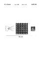
- FIG. 1 illustrates a light slab representation
- FIGS. 2A and 2B illustrate the representation of an oriented line in Cartesian space and in line space.
- FIGS. 3A to 3D illustrate the use of multiple light slabs to represent various views of an object.
- FIGS. 4A to 4D illustrate the density of samples in line space for different arrangements of light slabs.
- FIG. 5 illustrates the viewing geometry used to create light slabs from an array of perspective images.
- FIGS. 6A and 6B show two visualizations of a light field.
- FIG. 7 illustrates a technique for prefiltering a light field.
- FIG. 8 illustrates a prefiltering technique using an aperture.
- FIG. 9 is a perspective view of a camera gantry used to obtain digitized images in accordance with an embodiment of the invention.
- FIG. 10 is a perspective view of an object and lighting support system for digitizing images in accordance with an embodiment of the invention.
- FIG. 11 a representation of a two-stage compression pipeline.
- FIG. 12 illustrates a technique for resampling a light slab during display in accordance with the invention.
- FIGS. 13A-13C illustrates of the effects of interpolation during slice extraction.
- FIGS. 14A-14D shows example images from four light fields.
- FIGS. 15A-15B shows images extracted from compressed light fields.
- light field is defined as the radiance at a point in a given direction. This definition is equivalent to the plenoptic function introduced by Adelson and Bergen. See E. H. Adelson & J. R. Bergen, "The Plenoptic Function and the Elements of Early Vision,” Computation Models of Visual Processing, M. Landy and J. A. Movshon, eds., MIT Press, Cambridge, 1991. The phrase light field was coined by A. Gershun in his paper, "The Light Field,” Moscow, 1936, Journal of Mathematics and Physics, P. Moon & G. Timoshenko, trans., Vol. XVIII, MIT, 1939, pp. 51-151.
- McMillan and Bishop discuss the representation of five-dimensional light fields as a set of panoramic images at different three-dimensional locations. See McMillan, Plenoptic Modeling, supra.
- the five-dimensional representation may be reduced to four-dimensions in free space. This is a consequence of the fact that the radiance does not change along a line unless blocked.
- Four-dimensional light fields may be interpreted as functions on the space of oriented lines.
- the redundancy of the five-dimensional representation is undesirable for two reasons: first, redundancy increases the size of the total dataset, and second, redundancy complicates the reconstruction of the radiance function from its samples. This reduction in dimension has been used to simplify the representation of radiation emitted by luminaires. See R.
- a representation of a four-dimensional light field must be selected to parameterize the space of oriented lines based on several considerations, including: (1) calculation efficiency; (2) control over the set of lines; and (3) uniform sampling.
- the first consideration requires that the computation of the position of a line from its parameters be fast. More importantly, for the purposes of calculating new views, it should be easy to compute the line parameters given the viewing transformation and a pixel location.
- the second consideration is based on the realization that while the space of all lines is infinite, only a finite subset of line space is ever needed. For example, in the case of viewing an object we need only lines intersecting the convex hull of the object. Thus, there is an intuitive connection between the actual lines in three-dimensional space and line parameters.
- the third consideration reflects that given equally spaced samples in line parameter space, the pattern of lines in three-dimensional space should also be uniform. In this sense, a uniform sampling pattern is one where the number of lines in intervals between samples is constant everywhere.
- the present invention utilizes a representation which addresses these considerations.
- lines are parameterized by their intersections with two planes in arbitrary position.
- a convention is adopted wherein the coordinate system on a first plane 2 is (u,v) and on a second plane 4 is (s,t).
- An oriented line 6 is defined by connecting a point 8 on the u-v plane to a point 10 on the s-t plane.
- u, v, s, and t are restricted to lie between 0 and 1, and thus points on each plane are restricted to lie within a convex quadrilateral.
- This representation is referred to herein as a "light slab.”
- a light slab represents the beam of light entering one quadrilateral and exiting another quadrilateral.
- one of the planes may be placed at infinity. This is convenient since it permits lines to be parameterized by two points, or by a point and a direction. The latter proves useful for constructing light fields from orthographic images. Furthermore, if all calculations are performed using homogeneous coordinates, the two cases may be handled at no additional cost in computation.
- mapping from (u,v) to points on the plane is a projective map and involves only linear algebra (multiplying by a 3 ⁇ 3 matrix). More importantly, as will be discussed below, the inverse mapping from an image (x,y) to (u,v,s,t) is also a projective map. Methods using spherical or cylindrical coordinates require substantially more computation.
- FIGS. 2A and 2B use line space to illustrate some of the major concepts of our representation. In these figures, lines are shown in two dimensions to simplify visualization. It will be appreciated that the extension to three dimensions is straightforward.
- each oriented line may be represented in line space by a corresponding point.
- line space each oriented line is represented by a point and each set of lines by a region.
- the set of lines represented by a light slab and the set of lines intersecting the convex hull of an object are both regions in line space. All views of an object could be generated from one light slab if its set of lines completely surrounded the set of lines intersecting the convex hull of the object. Unfortunately, this is not possible. Therefore, it takes multiple light slabs to represent all possible views of an object. The system therefore tiles line space with a collection of light slabs.
- FIGS. 3A to 3D illustrate the use of multiple light slabs to represent various views of an object.
- FIG. 3A shows a single light slab 30.
- Light rays 32 connect points on two defining lines 34 and 36.
- FIG. 3B shows the corresponding line space visualizations of the light rays shown in FIG. 3A.
- FIG. 3C shows an arrangement 35 of four rotated copies 30a, 30b, 30c, 30d of the light slab 30 shown in FIG. 3A.
- FIG. 3D shows the corresponding line space visualizations for each light ray of these rotated copies.
- the envelope formed by the corresponding points in line space indicates the coverage of position and direction. Ideally, the coverage should be complete in ⁇ and as wide as possible in r.
- the single slab 30 in FIG. 3A does not provide full coverage in ⁇ , but the four-slab arrangement 35 in FIG. 3C does.
- the representation of FIG. 3C is narrow in r.
- Such an arrangement is suitable for inward-looking views of a small object placed at the origin. Illustratively, it was used to generate the light field of the lion object described below in reference to FIG. 14D.
- FIGS. 4A to 4D show the density of samples in line space for different arrangements of slabs.
- FIG. 4A shows a light slab defined by two lines 42 and 44 at right angles.
- FIG. 4C shows a light slab where one defining line is at infinity and the other line 46 lies along the x-axis. This arrangement generates rays passing through the defining line 46 with an angle between -45° and +45°.
- FIG. 4B shows the line space visualization corresponding to the light slab of FIG. 4A.
- FIG. 4D shows the line space visualization corresponding to the light slab of FIG. 4C.
- FIGS. 3A to 3D and FIGS. 4A to 4D demonstrate that no slab arrangement is perfect.
- slab arrangements with a singularity such as two polygons joined at a corner, are bad and should be avoided.
- slabs formed from parallel planes generate fairly uniform patterns.
- arrangements like the one shown in FIG. 4C are better than those with two finite plane (such as those shown in FIG. 3A).
- the spacing of samples in u-v should be roughly the same as s-t. If the observer is likely to stand near the u-v plane, then it may be acceptable to sample u-v less frequently than s-t.
- One method to create a light field is to choose a four-dimensional sampling pattern, and for each line sample, find the radiance. This is easily done directly for virtual environments by a ray tracer.
- the preferred approach to generate light fields is to assemble a collection of images of the environment. Alternatively, a spot radiometer may be used, but this approach may be tedious.
- a light slab is easily generated simply by rendering a two-dimensional array of images.
- Each image represents a slice of the four-dimensional light slab at a fixed u-v value and is formed by placing the center of projection of the virtual camera at the location of the sample on the u-v plane.
- the only issue is that the x-y samples of each image must correspond exactly with the s-t samples. As described below, this is easily done by performing a sheared perspective projection similar to that used to generate a stereo pair of images.
- FIG. 5 illustrates the viewing geometry to create a light slab from an array of perspective images.
- Each perspective is arranged at positions 52a-52d along the camera plane 54, which corresponds to the u-v plane utilizing the convention adopted herein.
- the focal plane 56 corresponds to the s-t plane.
- FIGS. 6A and 6B show the resulting four-dimensional light field utilizing the viewing geometry shown in FIG. 5.
- This light field can be visualized either as a u-v array of s-t images (FIG. 6A) or as an s-t array of u-v images (FIG. 6B).
- each image 60 in an array 62 represents the rays arriving at one point 64 on the u-v plane from all points on the s-t plane.
- each image 65 in array 66 represents the rays leaving one point 68 on the s-t plane bound for all points on the u-v plane.
- the images in FIG. 6A are off-axis (i.e.
- FIG. 6B look like reflectance maps. The latter occurs because the object has been placed astride the focal plane, making sets of rays leaving points on the focal plane similar in character to sets of rays leaving points on the object.
- a light slab may be formed from a two-dimensional array of orthographic views. This can be modeled by placing the u-v plane at infinity, as shown in FIG. 4A. In this case, each u-v sample corresponds to the direction of a parallel projection. Again, the only issue is to align the x-y and s-t samples of the image with the s-t quadrilateral.
- Another useful geometry consists of a two-dimensional array of outward looking (non-sheared) perspective views with fixed field of view.
- each image is a slice of the light slab with the s-t plane at infinity.
- the fact that all these cases are equally easy to handle with light slabs attests to the elegance of projective geometry. Light fields using each arrangement are described below and illustrated in FIG. 14.
- aliasing may be alleviated by filtering before sampling.
- a four-dimensional filter in the space of lines is employed. Such a filter is shown in FIG. 7 where a ray filter 76 is produced by the combination of a pixel filter 72 and an aperture filter 74.
- One possible embodiment employs a box filter.
- a weighted average of the radiances on all lines connecting sample squares in the u-v and s-t planes is computed.
- Light fields are then created from images generated by a camera placed on the u-v plane which is focused on the s-t plane.
- the filtering process corresponds to integrating both over a pixel corresponding to an s-t sample, and an aperture equal in size to a u-v sample. This technique is described in reference to FIG. 8.
- FIG. 8 illustrates a prefiltering technique using an aperture.
- a camera focuses on the s-t plane 86.
- a hypothetical film plane 85 is drawn behind the aperture 82 which is disposed in the u-v plane 84. Ignoring the aperture momentarily (for example, in the case of a pinhole camera that precisely images the s-t plane onto the film plane 85), integration over a pixel on the film plane is then equivalent to integrating over an s-t region bounded by the pixel.
- prefiltering has the desired effect of antialiasing the light field, it has what at first seems like an undesirable side effect--introducing blurriness due to depth of field.
- this blurriness is precisely correct for the situation described herein.
- a given object point will project to different locations in these two images.
- the distance between the two projected locations is called the stereo disparity.
- Extending this idea to multiple camera locations produces a sequence of images in which the object appears to jump by a distance equal to the disparity.
- This jumping is aliasing.
- Taking an image with a finite aperture causes points out of focus to be blurred on the film plane by a circle of confusion. Setting the diameter of the aperture to the spacing between camera locations causes the circle of confusion for each object point to be equal in size to its stereo disparity. This replaces the jumping with a sequence of blurred images.
- aliasing is removed by employing finite depth of field.
- Imagery may be based on either a flyaround of a small object or a flythrough of a large-scale scene. In the embodiment described in this section, the former approach was utilized. Thus, the generated imagery is inward looking. For example, the lion light field of FIG. 14D may be generated with the system shown in FIG. 9.
- FIGS. 9 and 10 An inexpensive approach to digitizing light fields is to move a handheld camera through the scene, populating the field from the resulting images. However, this approach necessitates estimating camera pose at each frame and interpolating the light field from scattered data--two challenging problems.
- the preferred embodiment described herein employs a computer-controlled camera gantry and digitized images on a regular grid. Such a system is shown in FIGS. 9 and 10.
- a spherical gantry has three advantages over a planar gantry: (a) it is easier to cover the entire range of viewing directions; (b) the sampling rate in direction space is more uniform; and (c) the distance between the camera and the object is fixed, providing sharper focus throughout the range of camera motion.
- a planar gantry has two advantages over a spherical gantry: (a) it is easier to build (the entire structure can be assembled from linear motion stages); and (b) it is closer to the light slab representation described above.
- the embodiment shown in FIG. 9 employs a planar gantry to obtain images of an object 96. While various components may be utilized, the illustrative embodiment shown includes a modified Cyberware MS motion platform with additional stepping motors which provide four degrees of freedom (horizontal translation, vertical translation, pan and tilt).
- a Panasonic WV-F300 3-CCD video camera 92 is used with a Canon f/1.7 10-120 mm zoom lens In use, the lens may be locked at its widest setting (10 mm) and mounted so that the pitch and yaw axes pass through the center of projection. While digitizing, the camera 92 is kept pointed at the center of the focal plane. Calibrations and alignments are verified with the aid of a Faro digitizing arm 94 which is accurate to 0.3 mm.
- An alternative implementation, in which the camera is moved along the surface of a sphere, might be a gantry design consisting of two concentric hemicycles similar to a gyroscope mounting.
- a gantry has been constructed by Apple Computer to acquire imagery for Quick-Time VR flyarounds. See S.E. Chen, "QuickTime VR--An Image-Based Approach to Virtual Environment Navigation," Proc. SIGGRAPH '95 (Los Angeles, Calif., Aug. 6-11, 1995), Computer Graphics Proceedings, Annual Conference Series, 1995, ACM SIGGRAPH pp. 29-38.
- the lighting in the Apple Computer system is attached to the moving camera, rendering it unsuitable for acquiring static light fields.
- a light field is built that allows 360 degrees of azimuthal viewing.
- a planar gantry involves acquiring four slabs each providing 90 degrees.
- FIG. 9 achieves this objective with a camera 92 equipped with pan and tilt motors, thereby enabling the use of a narrow-angle lens.
- the use of a rotating camera means that, in order to transfer the acquired image to the light slab representation it must be reprojected to lie on a common plane. This reprojection is equivalent to keystone correction in architectural photography.
- a disadvantage of planar gantries is that the distance from the camera to the object changes as the camera translates across the plane, making it difficult to keep the object in focus.
- the view camera 92 described in reference to FIG. 9 does not suffer from this problem because the ratio of object distance to image distance stays constant as the camera translates.
- servo-controlled focusing is an option, but changing the focus of a camera shifts its center of projection and changes the image magnification, complicating acquisition. This problem may be minimized by using strong lighting and a small aperture to maximize depth of field.
- Each sample in a light slab should represent the integral over a pixel, and these pixels should lie on a common focal plane, as discussed above.
- a view camera satisfies this constraint because its sensor translates in a plane.
- the use of a rotating camera means that the focal plane also rotates.
- the presence of a rotated focal plane will introduce no additional error into the light field. In the preferred embodiment, no artifacts were observed due to such a resampling process.
- Each sample in a light slab should also represent the integral over an aperture equal in size to a u-v sample.
- the use of a small aperture produces a light field with little or no u-v antialiasing.
- the apertures of many commercial video cameras are small.
- the required antialiasing may be approximated by averaging together some number of adjacent views, thereby creating a synthetic aperture.
- this technique requires a very dense spacing of views, which in turn requires rapid acquisition.
- FIG. 10 illustrates an object and lighting support.
- objects are mounted on a platform 108 attached to a tripod 102, such as a Bogen fluid-head tripod which can be rotated to four orientations spaced 90 degrees apart.
- a tripod 102 such as a Bogen fluid-head tripod which can be rotated to four orientations spaced 90 degrees apart.
- a rotating lighting system 104, 106 may be used to satisfy the requirement for fixed illumination. Illumination is provided by lights 104 attached to a ceiling mounted rotating hub 106 that is aligned with the rotational axis of the tripod 102. Illustratively, the lights 104 may comprise two 600W Lowell Omni spotlights. Preferably, a stationary diffuser panel (not shown) is hung between the spotlights and the gantry and the entire apparatus enclosed in black velvet to eliminate any stray light. Alternatively, a lighting system which exhibits fourfold symmetry could also be used.
- This procedure comprises the following steps. First, for each of four orientations, the camera is translated through a regular grid of camera positions. Next, the camera is panned and tilted at each position to point at the center of the object, along the axis of rotation of the tripod. The image is then acquired, and using standard texture mapping algorithms known in the art, the image is reprojected to lie on a common plane as described above.
- Table II set forth below, provides an illustrative set of acquisition parameters.
- the distance between the camera positions (3.125 cm) exceeds the diameter of the aperture (1.25 mm). Accordingly, this example could benefit from denser spacing and a synthetic aperture as noted above.
- Light field arrays are large, and to make creation, transmission, and display of light fields practical, they preferably should be compressed.
- Several compression techniques are available. However, we have discovered that the following unique characteristics of light fields are significant in determining a proper compression technique for use in connection with the invention.
- data coherence is a significant characteristic of light fields with respect to compression.
- Light fields exhibit coherence in all four dimensions.
- the smooth regions in FIG. 6A indicate that this light field contains coherence in s and t
- the smooth regions in FIG. 6B indicated that the light field contains coherence in u and v.
- the former corresponds to our usual notion of interpixel coherence in a perspective view.
- the latter can be interpreted either as the interframe coherence one expects in a motion sequence or as the smoothness one expects in the bidirectional reflectance distribution function (BRDF) for a diffuse or moderately specular surface. Occlusions introduce discontinuities in both cases.
- BRDF bidirectional reflectance distribution function
- variable bitrate coders may require scanlines, tiles or frames to be decoded at once. More particularly, such coders include variable bitrate vector quantization and the Huffman or arithmetic coders used in JPEG or MPEG. Predictive coding schemes further complicate access because pixels depend on previously decoded pixels, scanlines, or frames. This poses a problem for light fields since the set of samples referenced when extracting an image from a light field are dispersed in memory. As the observer moves, the access patterns change in complex ways. Therefore, a compression technique that supports low-cost random access to individual samples is preferred.
- asymmetry is a characteristic which relates to a proper compression technique.
- Applications of compression can be classified as symmetric or asymmetric depending on the relative time spent encoding versus decoding. In a preferred embodiment of the invention, it is assumed that light fields are assembled and compressed ahead of time, making this an asymmetric application.
- a compression scheme can be decoded without hardware assistance.
- software decoders have been demonstrated for standards like JPEG and MPEG, these implementations consume the full power of a modem microprocessor.
- the display method has additional work to perform as described more particularly below. Therefore, it is preferred that a compression technique be utilized which can be decoded quickly.
- the preferred embodiment utilizes a two-stage pipeline compression scheme consisting of fixed rate vector quantization followed by entropy coding, such as Lempel-Ziv coding. This technique is illustrated in reference to FIG. 11.
- a light field 110 is partitioned into tiles, which are encoded using vector quantization (VQ) 112 to form an array of codebook indices.
- VQ vector quantization
- the codebook 114 and the array of indices 116 are further compressed using Lempel-Ziv (LZ) coding.
- LZ Lempel-Ziv
- decompression occurs in two stages: entropy decoding as the file is loaded into memory, and dequantization on demand during interactive viewing.
- Typical file sizes for this example are shown in FIG. 11 beside each stage.
- Vector quantization is a lossy compression technique wherein a vector of samples is quantized to one of a number of predetermined reproduction vectors.
- a reproduction vector is called a codeword
- the set of codewords available to encode a source is called the codebook.
- Codebooks are constructed during a training phase in which the quantizer is asked to find a set of codewords that best approximates a set of sample vectors, called the training set.
- the quality of a codeword is typically characterized using mean-squared error (MSE) (i.e.
- encoding consists of partitioning the source into vectors and finding for each vector the closest approximating codeword from the codebook.
- Decoding consists of looking up indices in the codebook and outputting the codewords found there--a very fast operation. Indeed, decoding speed is one of the primary advantages of vector quantization.
- two-dimensional or four-dimensional tiles of the light field are used, yielding 12-dimensional or 48-dimensional vectors, respectively.
- the former takes advantage of coherence in s and t only, while the latter takes advantage of coherence in all four dimensions.
- a representative subset of each light field is trained to be compressed, and then the resulting codebook is transmitted along with the codeword index array. Since light fields are large, even after compression, the additional overhead of transmitting a codebook is small, typically less than 20%. By training on a subset rather than the entire light field, the expense of training is reduced.
- the output of vector quantization is a sequence of fixed-rate codebook indices.
- Each index is log N bits where N is the number of codewords in the codebook, so the compression rate of the quantizer is (kl)/(log N) where k is the number of elements per vector (i.e., the dimension), and l is the number of bits per element, usually eight.
- the second stage of the compression pipeline shown in FIG. 11 is an entropy coder designed to decrease the cost of representing high-probability code indices. Since objects are typically rendered or photographed against a constant-color background, the array may contain many tiles that occur with high probability.
- Decompression occurs in two stages.
- the first stage--gzip decoding-- is performed as the file is loaded into memory.
- the output of this stage is a codebook and an array of code indices packed in 16-bit words.
- some efficiency has been lost by this decoding, the light field is still compressed 24:1, and it is now represented in a way that supports random access.
- the display engine requests samples of the light field.
- Each request consists of a (u,v,s,t,) coordinate tuple.
- a subscripting calculation is performed to determine which sample tile is being addressed.
- Each tile corresponds to one quantization vector and is thus represented in the index array by a single entry. Looking this index up in the codebook reveals a vector of sample values.
- a second subscripting calculation is then performed, providing the offset of the requested sample within the vector.
- the final part of the technique according to the invention is a real time viewer that constructs and displays an image from the light slab given the imaging geometry.
- the viewer must resample a two-dimensional slice of lines from the four-dimensional light field; each line represents a ray through the eye point and a pixel center as shown in FIG. 12.
- a big advantage of the light slab representation is the efficiency of the inverse calculation of the line parameters.
- the (u,v) and (s,t) parameters are calculated by determining the point of intersection of an image ray with each plane.
- any ray tracer can easily be adapted to use light slabs.
- a polygonal rendering system also may be used to view a light slab.
- the transformation from image coordinates (x,y) to both the (u,v) and the (s,t) coordinates is a projective map. Therefore, computing the line coordinates can be done using texture mapping.
- the uv quadrilateral is drawn using the current viewing transformation, and during scan conversion the (u/w,v/w,w) coordinates at the corners of the quadrilateral are interpolated.
- a similar procedure is used to generate the (s,t) coordinates by drawing the st quadrilateral.
- the inverse transformation from (x,y) to (u,v,s,t) reduces essentially to two texture coordinate calculations per ray. This approach is cheap and can be done in real time, and is supported in many rendering systems, both hardware and software.
- each light slab is drawn sequentially. If the set of lines in the collection of light slabs do not overlap, then each pixel is drawn only once, resulting in increased efficiency. To further increase efficiency, "back-facing" light slabs are culled.
- the second step involves resampling the radiance.
- the ideal resampling process involves first reconstructing the function from the original samples, and then applying a bandpass filter to the reconstructed function to remove high frequencies that may cause aliasing.
- the resampling process may be approximated by simply interpolating the four-dimensional function from the nearest samples. This is correct only if the new sampling rate is greater than the original sampling rate, which is usually the case when displaying light fields. However, if the image of the light field is very small, prefiltering is applied. This could easily be done with a four-dimensional variation of the standard midmapping algorithm. See L. Williams, "Pyramidal Parametrics," Computer Graphics (Proc. Siggraph '83), Vol. 17, No. 3, July 1983, pp. 1-11.
- FIGS. 13A to 13C show the effect of nearest neighbor versus linear interpolation on the u-v plane versus quadrilinear interpretation of the full 4D function.
- FIG. 13A shows the results where no interpolation is used.
- FIG. 13B shows linear interpolation in u-v only.
- FIG. 13C shows quadrilinear interpolation in u-v-s-t.
- Quadrilinear interpolation coupled with the proper prefiltering generates images with few aliasing artifacts. The improvement is particularly dramatic when the object or camera is moving. However, quadralinear filtering is fairly expensive and dominates the running time of the viewer. In many situations, the sampling rates in the u-v and s-t planes may be different, and then the benefits of filtering one plane may be much greater than the other plane.
- FIGS. 14A to 14D show images extracted from four light fields.
- the first is a buddha constructed from rendered images.
- the model is an irregular polygon mesh constructed from range data.
- the input images were generated using RenderMan, which also provided the machinery for computing pixel and aperture antialiasing.
- the light field configuration was a single slab similar to that shown in FIG. 3A.
- a second light field shown in FIG. 14B is a human abdomen constructed from volume renderings.
- the two tan-colored organs on either side of the spine are the kidneys.
- the input images were orthographic views, so a slab with one plane at infinity was employed as shown in FIG. 4C. Because an orthographic image contains rays of constant direction, more input images were generated than in the example shown in FIG. 4A in order to provide the angular range needed for creating perspective views.
- the images include pixel antialiasing but no aperture antialiasing. However, the dense spacing of input images reduces aperture aliasing artifacts to a minimum.
- FIG. 14C A third example shown in FIG. 14C is an outward-looking light field depicting a hallway in Berkeley's Soda Hall, rendered using a radiosity program. To allow a full range of observer motion while optimizing sampling uniformity, four slabs were used with one plane at infinity. Thus this example corresponds to a four-slab version of FIG. 4C.
- the input images were rendered on an SGI RealityEngine, using the accumulation buffer to provide both pixel and aperture antialiasing.
- a fourth example shown in FIG. 14D is a light field constructed from digitized images.
- the scene is of a toy lion, and the light field consists of four slabs as shown in FIG. 3C, allowing the observer to walk completely around the object.
- the sensor and optical system provide pixel antialiasing, but the aperture diameter was too small to provide correct aperture antialiasing.
- the light field exhibits some aliasing, which appears as double images.
- Table I summarizes the statistics of each light field shown in FIGS. 14A to 14D.
- Table II provides acquisition parameters for the lion dataset (FIG. 14D).
- Table III gives the performance of the compression pipeline on two representative datasets.
- Table IV summarizes the performance of our interactive viewer operating on the lion light field.
- the buddha (FIG. 14A) was compressed using a two-dimensional tiling of the light field, yielding a total compression rate of 45:1.
- the lion (FIG. 14D) was compressed using a four-dimensional tiling, yielding a higher compression rate of 118:1.
- the compressed buddha is indistinguishable from the original; the compressed lion exhibits some artifacts, but only at high magnifications. Representative images are shown in FIGS. 15A and 15B. Based on other experiments at higher rates, we have found that as a general rule, the artifacts become objectionable only above 200:1.
- Table III describes compression statistics for two light fields.
- the buddha light field was compressed using two-dimensional tiles of RGB pixels, forming twelve-dimensional vectors.
- the lion light field was compressed using four-dimensional tiles (two-dimensional tiles of RGB pixels from each of 2 ⁇ 2 adjacent camera positions), forming 48-dimensional vectors.
- Bytes per codeword index include padding as described above.
- Peak signal-to-noise ratio (PSNR) is computed as 10 log 10 (255 2 /MSE).
- Table IV indicates the performance of the interactive viewer for the lion field. Displayed images are 192 ⁇ 192 pixels. Sample extraction includes VQ decoding and sample interpolation. Display overhead includes reading a mouse, computing observer position, and copying the images to a frame buffer. Timings are for a software-only implementation on a 250 MHz MIPS 4400 processor. As the table shows, interactive playback rates are achieved for reasonable image sizes. Note that the size of the light field has no effect on playback rate; only the image size matters. Memory size is not an issue because the compressed fields are small.
- the observer is restricted to regions of space free of occluders.
- This limitation can be addressed by stitching together multiple light fields based on a partition of the scene geometry into convex regions. If the light fields are augmented to include Z-depth, the regions need not even be convex.
- the illumination must be fixed.
- this limitation can be addressed by augmenting light fields to include surface normals and optical properties.
- the inventive technique may be compared with depth-based or correspondence-based view interpolation.
- a three-dimensional model is created to improve quality of the interpolation and hence decrease the number of pre-acquired images.
- a much larger number of images is acquired.
- this may seem like a disadvantage.
- simple compression schemes are able to find and exploit this same three-dimensional structure.
- simple four-dimensional block coding leads to compression rates of over 100:1. Given the success of the compression, a high density compressed light field has an advantage over other approaches because the resampling process is simpler, and no explicit three-dimensional structure must be found or stored.
Abstract
Description
              TABLE I
______________________________________
Statistics of the light fields shown in FIGS. 14A-14D.
             buddha   kidney   hallway
                                      lion
______________________________________
Number of slabs
             1        1        4      4
Images per slab
             16 × 16
                      64 × 64
                               64 × 32
                                      32 × 16
Total images 256      4096     8192   2048
Pixels per image
             256.sup.2
                      128.sup.2
                               256.sup.2
                                      256.sup.2
Raw size (MB)
             256      201      1608   402
Prefiltering uvst     st only  uvst   st only
______________________________________
TABLE II ______________________________________ Acquisition parameters for the lion field. ______________________________________ Camera motion translation per slab 100 cm × 50 cm pan and tilt per slab 90° × 45° number ofslabs 4 slabs 90° apart total pan and tilt 360° × 45° Sampling density distance to object 50 cm camera pan per sample 3.6° camera translation per sample 3.125 cm Aperture focal distance oflens 10 mm F-number f/8 aperture diameter 1.25 mm Acquisition time time per image 3 secondstotal acquisition time 4 hours ______________________________________
              TABLE III
______________________________________
Compression statistics for two light fields.
                 buddha      lion
______________________________________
Vector quantization
raw size (MB)    50.3        402.7
fraction in training set
                 5%          3%
samples per tile 2 × 2 × 1 × 1
                             2 × 2 × 2 × 2
bytes per sample 3           3
vector dimension 12          48
number of codewords
                 8192        16384
codebook size (MB)
                 0.1         0.8
bytes per codeword index
                 2           2
index array size (MB)
                 8.4         16.8
total size (MB)  8.5         17.6
compression rate 6:1         23:1
Entropy coding
gzipped codebook (MB)
                 0.1         0.6
gzipped index array (MB)
                 1.0         2.8
total size (MB)  1.1         3.4
compression due to gzip
                 8:1         5:1
total compression
                 45:1        118:1
Compression performance
training time    15 mins     4 hrs
encoding time    1 mins      8 mins
original entropy (bits/pixel)
                 4.2         2.9
image quality (PSNR)
                 36          27
______________________________________
              TABLE IV
______________________________________
Display performance for the lion field.
Display times (ms)
              no bilerp  uv lerp uvst lerp
______________________________________
coordinate calculation
              13         13      13
sample extraction
              14         59      214
overhead      3          3       3
total         30         75      230
______________________________________
Claims (27)
Priority Applications (3)
| Application Number | Priority Date | Filing Date | Title |
|---|---|---|---|
| US08/848,569 US6097394A (en) | 1997-04-28 | 1997-04-28 | Method and system for light field rendering |
| PCT/US1998/006662 WO1998049667A2 (en) | 1997-04-28 | 1998-04-01 | Method and system for light field rendering |
| AU69500/98A AU6950098A (en) | 1997-04-28 | 1998-04-01 | Method and system for light field rendering |
Applications Claiming Priority (1)
| Application Number | Priority Date | Filing Date | Title |
|---|---|---|---|
| US08/848,569 US6097394A (en) | 1997-04-28 | 1997-04-28 | Method and system for light field rendering |
Publications (1)
| Publication Number | Publication Date |
|---|---|
| US6097394A true US6097394A (en) | 2000-08-01 |
Family
ID=25303658
Family Applications (1)
| Application Number | Title | Priority Date | Filing Date |
|---|---|---|---|
| US08/848,569 Expired - Lifetime US6097394A (en) | 1997-04-28 | 1997-04-28 | Method and system for light field rendering |
Country Status (3)
| Country | Link |
|---|---|
| US (1) | US6097394A (en) |
| AU (1) | AU6950098A (en) |
| WO (1) | WO1998049667A2 (en) |
Cited By (254)
| Publication number | Priority date | Publication date | Assignee | Title |
|---|---|---|---|---|
| US6204852B1 (en) * | 1998-12-09 | 2001-03-20 | Lucent Technologies Inc. | Video hand image three-dimensional computer interface |
| US20010035906A1 (en) * | 2000-01-21 | 2001-11-01 | Izumi Fukuda | Entertainment apparatus, storage medium and object display method |
| US6362822B1 (en) * | 1999-03-12 | 2002-03-26 | Terminal Reality, Inc. | Lighting and shadowing methods and arrangements for use in computer graphic simulations |
| US20020122037A1 (en) * | 2001-02-21 | 2002-09-05 | Konami Computer Entertainment Japan, Inc. | Image expression method and program used therefor |
| US6452593B1 (en) * | 1999-02-19 | 2002-09-17 | International Business Machines Corporation | Method and system for rendering a virtual three-dimensional graphical display |
| US6452594B1 (en) * | 1999-07-27 | 2002-09-17 | Isurftv | Method and apparatus for using a 3D graphics pipeline and 3D imaging for cost effective watermarking |
| US6476805B1 (en) | 1999-12-23 | 2002-11-05 | Microsoft Corporation | Techniques for spatial displacement estimation and multi-resolution operations on light fields |
| US6502097B1 (en) | 1999-12-23 | 2002-12-31 | Microsoft Corporation | Data structure for efficient access to variable-size data objects |
| US20030004694A1 (en) * | 2001-05-29 | 2003-01-02 | Daniel G. Aliaga | Camera model and calibration procedure for omnidirectional paraboloidal catadioptric cameras |
| US6549308B1 (en) * | 2000-01-11 | 2003-04-15 | Zebra Imaging, Inc. | Unibiased light field models for rendering and holography |
| US6549203B2 (en) * | 1999-03-12 | 2003-04-15 | Terminal Reality, Inc. | Lighting and shadowing methods and arrangements for use in computer graphic simulations |
| US6636627B1 (en) * | 1999-07-12 | 2003-10-21 | Fuji Photo Film Co., | Light source direction estimating method and apparatus |
| US6642924B1 (en) * | 2000-11-02 | 2003-11-04 | Microsoft Corporation | Method and system for obtaining visual information from an image sequence using visual tunnel analysis |
| US6670957B2 (en) * | 2000-01-21 | 2003-12-30 | Sony Computer Entertainment Inc. | Entertainment apparatus, storage medium and object display method |
| US6674922B1 (en) * | 1999-03-26 | 2004-01-06 | Canon Kabushiki Kaisha | Image processing method, image processing apparatus, and storage medium |
| US6697062B1 (en) * | 1999-08-06 | 2004-02-24 | Microsoft Corporation | Reflection space image based rendering |
| US6724384B2 (en) | 2001-05-16 | 2004-04-20 | International Business Machines Corporation | System and method for organization and delivery of data for virtual walkthroughs |
| US6762746B2 (en) | 2000-01-21 | 2004-07-13 | Sony Computer Entertainment Inc. | Entertainment apparatus, storage medium and operation method of manipulating object |
| US20040150643A1 (en) * | 2002-11-15 | 2004-08-05 | George Borshukov | Method for digitally rendering an object using measured BRDF data |
| US20040212625A1 (en) * | 2003-03-07 | 2004-10-28 | Masahiro Sekine | Apparatus and method for synthesizing high-dimensional texture |
| US20040240746A1 (en) * | 2003-05-30 | 2004-12-02 | Aliaga Daniel G. | Method and apparatus for compressing and decompressing images captured from viewpoints throughout N-dimensioanl space |
| US20040240741A1 (en) * | 2003-05-30 | 2004-12-02 | Aliaga Daniel G. | Method and system for creating interactive walkthroughs of real-world environment from set of densely captured images |
| US20040240707A1 (en) * | 2003-05-30 | 2004-12-02 | Aliaga Daniel G. | Method and apparatus for finding feature correspondences between images captured in real-world environments |
| US20040239756A1 (en) * | 2003-05-30 | 2004-12-02 | Aliaga Daniel G. | Method and apparatus for computing error-bounded position and orientation of panoramic cameras in real-world environments |
| US6831643B2 (en) | 2001-04-16 | 2004-12-14 | Lucent Technologies Inc. | Method and system for reconstructing 3D interactive walkthroughs of real-world environments |
| US20040252892A1 (en) * | 2003-01-30 | 2004-12-16 | Yasunobu Yamauchi | Texture image compressing device and method, texture image decompressing device and method, data structures and storage medium |
| US20050078178A1 (en) * | 2003-10-10 | 2005-04-14 | International Business Machines Corporation | System and method for providing position-independent pose estimation |
| US6895126B2 (en) | 2000-10-06 | 2005-05-17 | Enrico Di Bernardo | System and method for creating, storing, and utilizing composite images of a geographic location |
| US6906708B1 (en) * | 1999-03-26 | 2005-06-14 | Canon Kabushiki Kaisha | Image processing method and apparatus, and storage medium |
| US20050168465A1 (en) * | 2003-09-24 | 2005-08-04 | Setsuji Tatsumi | Computer graphics system, computer graphics reproducing method, and computer graphics program |
| US20050174348A1 (en) * | 2002-10-30 | 2005-08-11 | Yoshiyuki Sakaguchi | Image processing device, image processing program, recording medium recording the program, image processing method, and shading information acquisition device |
| US20050230641A1 (en) * | 2004-04-05 | 2005-10-20 | Won Chun | Data processing for three-dimensional displays |
| WO2006049384A1 (en) * | 2004-11-08 | 2006-05-11 | Electronics And Telecommunications Research Institute | Apparatus and method for producting multi-view contents |
| US7064753B2 (en) * | 2002-09-19 | 2006-06-20 | Namco Ltd. | Image generating method, storage medium, image generating apparatus, data signal and program |
| US20070018994A1 (en) * | 2005-07-20 | 2007-01-25 | Kabushiki Kaisha Toshiba | Texture encoding apparatus, texture decoding apparatus, method, and program |
| US20070030342A1 (en) * | 2004-07-21 | 2007-02-08 | Bennett Wilburn | Apparatus and method for capturing a scene using staggered triggering of dense camera arrays |
| US20070057968A1 (en) * | 2005-09-15 | 2007-03-15 | Fossum Gordon C | System and method for adaptive span computation during ray casting |
| US20070076016A1 (en) * | 2005-10-04 | 2007-04-05 | Microsoft Corporation | Photographing big things |
| US20070187574A1 (en) * | 2006-02-13 | 2007-08-16 | Ge Inspection Technologies, Lp | Electronic imaging device with photosensor arrays |
| US20070201737A1 (en) * | 2003-11-26 | 2007-08-30 | Wenli Cai | System And Method For Vascular Visualization Using Planar Reformation Of Vascular Central Axis Surface With Biconvex Slab |
| US20070252074A1 (en) * | 2004-10-01 | 2007-11-01 | The Board Of Trustees Of The Leland Stanford Junio | Imaging Arrangements and Methods Therefor |
| US20080007559A1 (en) * | 2006-06-30 | 2008-01-10 | Nokia Corporation | Apparatus, method and a computer program product for providing a unified graphics pipeline for stereoscopic rendering |
| US20080044078A1 (en) * | 2006-08-18 | 2008-02-21 | William Edward Mantzel | Data Structure Representing a Plenoptic Function via Compressible Layered Orthographic Projections from Multiple Orientations |
| US20080068386A1 (en) * | 2006-09-14 | 2008-03-20 | Microsoft Corporation | Real-Time Rendering of Realistic Rain |
| WO2008041061A1 (en) | 2006-10-05 | 2008-04-10 | Vestel Elektronik Sanayi Ve Ticaret A.S. | Watermark detection method for broadcasting |
| US20080124070A1 (en) * | 2006-11-28 | 2008-05-29 | Chia-Kai Liang | Camera using programmable aperture |
| US20080131019A1 (en) * | 2006-12-01 | 2008-06-05 | Yi-Ren Ng | Interactive Refocusing of Electronic Images |
| US20080152215A1 (en) * | 2006-12-26 | 2008-06-26 | Kenichi Horie | Coding method, electronic camera, recording medium storing coded program, and decoding method |
| US20080187305A1 (en) * | 2007-02-06 | 2008-08-07 | Ramesh Raskar | 4D light field cameras |
| US20080193026A1 (en) * | 2007-02-09 | 2008-08-14 | Kenichi Horie | Decoding method, decoding apparatus, storage medium in which decoding program is stored, and electronic camera |
| US20080266655A1 (en) * | 2005-10-07 | 2008-10-30 | Levoy Marc S | Microscopy Arrangements and Approaches |
| US20090041381A1 (en) * | 2007-08-06 | 2009-02-12 | Georgiev Todor G | Method and Apparatus for Radiance Processing by Demultiplexing in the Frequency Domain |
| US20090080766A1 (en) * | 2007-09-10 | 2009-03-26 | Herbert Daxauer | Method and apparatus for the Three-Dimensional Digitization of objects |
| US20090128669A1 (en) * | 2006-02-07 | 2009-05-21 | Yi-Ren Ng | Correction of optical aberrations |
| US20090190852A1 (en) * | 2008-01-28 | 2009-07-30 | Samsung Electronics Co., Ltd. | Image inpainting method and apparatus based on viewpoint change |
| US7602404B1 (en) * | 1998-04-17 | 2009-10-13 | Adobe Systems, Incorporated | Method and apparatus for image assisted modeling of three-dimensional scenes |
| US20090268970A1 (en) * | 2008-04-29 | 2009-10-29 | Sevket Derin Babacan | Method and Apparatus for Block-Based Compression of Light-field Images |
| US20100020187A1 (en) * | 2006-04-04 | 2010-01-28 | Georgiev Todor G | Plenoptic camera |
| US20100091133A1 (en) * | 2008-10-10 | 2010-04-15 | Lim Jae-Guyn | Image processing apparatus and method |
| US20100128037A1 (en) * | 2008-11-25 | 2010-05-27 | Sony Computer Entertainment America Inc. | Method and apparatus for aggregating light sources per-vertex in computer graphics |
| US20100129048A1 (en) * | 2008-11-25 | 2010-05-27 | Colvin Pitts | System and Method for Acquiring, Editing, Generating and Outputting Video Data |
| US20100128038A1 (en) * | 2008-11-25 | 2010-05-27 | Sony Computer Entertainment America Inc. | Method and apparatus for interpolating color and direction as one entity in computer graphics |
| EP2192546A1 (en) | 2008-12-01 | 2010-06-02 | Nederlandse Organisatie voor toegepast-natuurwetenschappelijk Onderzoek TNO | Method for recognizing objects in a set of images recorded by one or more cameras |
| US20100141802A1 (en) * | 2008-12-08 | 2010-06-10 | Timothy Knight | Light Field Data Acquisition Devices, and Methods of Using and Manufacturing Same |
| US20100194921A1 (en) * | 2009-02-05 | 2010-08-05 | Sony Corporation | Image pickup apparatus |
| US20100232499A1 (en) * | 2007-05-30 | 2010-09-16 | Nxp B.V. | Method of determining an image distribution for a light field data structure |
| US20100265385A1 (en) * | 2009-04-18 | 2010-10-21 | Knight Timothy J | Light Field Camera Image, File and Configuration Data, and Methods of Using, Storing and Communicating Same |
| US20110211824A1 (en) * | 2008-01-23 | 2011-09-01 | Georgiev Todor G | Methods and Apparatus for Full-Resolution Light-Field Capture and Rendering |
| US20110234841A1 (en) * | 2009-04-18 | 2011-09-29 | Lytro, Inc. | Storage and Transmission of Pictures Including Multiple Frames |
| US20120068955A1 (en) * | 2004-01-02 | 2012-03-22 | Smart Technologies Ulc | Pointer tracking across multiple overlapping coordinate input sub-regions defining a generally contiguous input region |
| US8189089B1 (en) | 2009-01-20 | 2012-05-29 | Adobe Systems Incorporated | Methods and apparatus for reducing plenoptic camera artifacts |
| US8189065B2 (en) | 2008-01-23 | 2012-05-29 | Adobe Systems Incorporated | Methods and apparatus for full-resolution light-field capture and rendering |
| US20120140024A1 (en) * | 2010-12-03 | 2012-06-07 | Fly's Eye Imaging, LLC | Method of displaying an enhanced three-dimensional images |
| US8228417B1 (en) | 2009-07-15 | 2012-07-24 | Adobe Systems Incorporated | Focused plenoptic camera employing different apertures or filtering at different microlenses |
| US20120197600A1 (en) * | 2011-01-31 | 2012-08-02 | Honeywell International Inc. | Sensor placement and analysis using a virtual environment |
| US8244058B1 (en) | 2008-05-30 | 2012-08-14 | Adobe Systems Incorporated | Method and apparatus for managing artifacts in frequency domain processing of light-field images |
| US20120229682A1 (en) * | 2009-01-26 | 2012-09-13 | The Board Of Trustees Of The Leland Stanford Junior University | Correction of Optical Abberations |
| US8290358B1 (en) | 2007-06-25 | 2012-10-16 | Adobe Systems Incorporated | Methods and apparatus for light-field imaging |
| US8315476B1 (en) | 2009-01-20 | 2012-11-20 | Adobe Systems Incorporated | Super-resolution with the focused plenoptic camera |
| US8345144B1 (en) | 2009-07-15 | 2013-01-01 | Adobe Systems Incorporated | Methods and apparatus for rich image capture with focused plenoptic cameras |
| US8358366B1 (en) | 2010-05-28 | 2013-01-22 | Adobe Systems Incorporate | Methods and apparatus for high-speed digital imaging |
| US20130063562A1 (en) * | 2011-09-09 | 2013-03-14 | Samsung Electronics Co., Ltd. | Method and apparatus for obtaining geometry information, lighting information and material information in image modeling system |
| US8400555B1 (en) | 2009-12-01 | 2013-03-19 | Adobe Systems Incorporated | Focused plenoptic camera employing microlenses with different focal lengths |
| US8432435B2 (en) | 2011-08-10 | 2013-04-30 | Seiko Epson Corporation | Ray image modeling for fast catadioptric light field rendering |
| US8432434B2 (en) * | 2011-07-08 | 2013-04-30 | Mitsubishi Electric Research Laboratories, Inc. | Camera and method for focus based depth reconstruction of dynamic scenes |
| US20130229486A1 (en) * | 2010-08-03 | 2013-09-05 | Cornell University | Angle sensitive pixel (asp)-based image processing system, method, and applications |
| US20130342526A1 (en) * | 2012-06-26 | 2013-12-26 | Yi-Ren Ng | Depth-assigned content for depth-enhanced pictures |
| US20140003732A1 (en) * | 2012-06-28 | 2014-01-02 | Canon Kabushiki Kaisha | Method and apparatus for compressing or decompressing light field images |
| US8665341B2 (en) | 2010-08-27 | 2014-03-04 | Adobe Systems Incorporated | Methods and apparatus for rendering output images with simulated artistic effects from focused plenoptic camera data |
| US20140092281A1 (en) * | 2012-09-28 | 2014-04-03 | Pelican Imaging Corporation | Generating Images from Light Fields Utilizing Virtual Viewpoints |
| US20140098191A1 (en) * | 2012-10-05 | 2014-04-10 | Vidinoti Sa | Annotation method and apparatus |
| JP2014086968A (en) * | 2012-10-25 | 2014-05-12 | Ricoh Co Ltd | Image processing device, image processing method, and program |
| US8724000B2 (en) | 2010-08-27 | 2014-05-13 | Adobe Systems Incorporated | Methods and apparatus for super-resolution in integral photography |
| US8749620B1 (en) | 2010-02-20 | 2014-06-10 | Lytro, Inc. | 3D light field cameras, images and files, and methods of using, operating, processing and viewing same |
| US8749694B2 (en) | 2010-08-27 | 2014-06-10 | Adobe Systems Incorporated | Methods and apparatus for rendering focused plenoptic camera data using super-resolved demosaicing |
| US8768102B1 (en) | 2011-02-09 | 2014-07-01 | Lytro, Inc. | Downsampling light field images |
| US20140218612A1 (en) * | 2013-02-06 | 2014-08-07 | Robert Bosch Gmbh | Multiple field-of-view video streaming |
| US8803918B2 (en) | 2010-08-27 | 2014-08-12 | Adobe Systems Incorporated | Methods and apparatus for calibrating focused plenoptic camera data |
| US8811769B1 (en) | 2012-02-28 | 2014-08-19 | Lytro, Inc. | Extended depth of field and variable center of perspective in light-field processing |
| US8817015B2 (en) | 2010-03-03 | 2014-08-26 | Adobe Systems Incorporated | Methods, apparatus, and computer-readable storage media for depth-based rendering of focused plenoptic camera data |
| US20140247364A1 (en) * | 2011-11-04 | 2014-09-04 | Empire Technology Development Llc | Ir signal capture for images |
| US8831377B2 (en) | 2012-02-28 | 2014-09-09 | Lytro, Inc. | Compensating for variation in microlens position during light-field image processing |
| US8866920B2 (en) | 2008-05-20 | 2014-10-21 | Pelican Imaging Corporation | Capturing and processing of images using monolithic camera array with heterogeneous imagers |
| US8870757B2 (en) | 2010-03-02 | 2014-10-28 | Siemens Aktiengesellschaft | Method, device and endoscopy capsule to detect information about the three-dimensional structure of the inner surface of a body cavity |
| US8885059B1 (en) | 2008-05-20 | 2014-11-11 | Pelican Imaging Corporation | Systems and methods for measuring depth using images captured by camera arrays |
| US20140340389A1 (en) * | 2013-05-17 | 2014-11-20 | Nvidia Corporation | System, method, and computer program product to produce images for a near-eye light field display |
| US8948545B2 (en) | 2012-02-28 | 2015-02-03 | Lytro, Inc. | Compensating for sensor saturation and microlens modulation during light-field image processing |
| CN104469372A (en) * | 2014-11-06 | 2015-03-25 | 中国科学院计算技术研究所 | Method and system for compressing light field image collected by microlens array |
| US8997021B2 (en) | 2012-11-06 | 2015-03-31 | Lytro, Inc. | Parallax and/or three-dimensional effects for thumbnail image displays |
| US8995785B2 (en) | 2012-02-28 | 2015-03-31 | Lytro, Inc. | Light-field processing and analysis, camera control, and user interfaces and interaction on light-field capture devices |
| US9001226B1 (en) | 2012-12-04 | 2015-04-07 | Lytro, Inc. | Capturing and relighting images using multiple devices |
| US9025894B2 (en) | 2011-09-28 | 2015-05-05 | Pelican Imaging Corporation | Systems and methods for decoding light field image files having depth and confidence maps |
| US9030550B2 (en) | 2011-03-25 | 2015-05-12 | Adobe Systems Incorporated | Thin plenoptic cameras using solid immersion lenses |
| US9041824B2 (en) | 2010-12-14 | 2015-05-26 | Pelican Imaging Corporation | Systems and methods for dynamic refocusing of high resolution images generated using images captured by a plurality of imagers |
| US20150156470A1 (en) * | 2013-11-04 | 2015-06-04 | Massachusetts Institute Of Technology | Reducing View Transitions Artifacts In Automultiscopic Displays |
| WO2015106031A2 (en) | 2014-01-10 | 2015-07-16 | Ostendo Technologies, Inc. | Methods for full parallax compressed light field 3d imaging systems |
| US9100635B2 (en) | 2012-06-28 | 2015-08-04 | Pelican Imaging Corporation | Systems and methods for detecting defective camera arrays and optic arrays |
| US9100586B2 (en) | 2013-03-14 | 2015-08-04 | Pelican Imaging Corporation | Systems and methods for photometric normalization in array cameras |
| US20150222873A1 (en) * | 2012-10-23 | 2015-08-06 | Yang Li | Dynamic stereo and holographic image display |
| US20150235476A1 (en) * | 2012-02-21 | 2015-08-20 | Pelican Imaging Corporation | Systems and Method for Performing Depth Based Image Editing |
| US9124864B2 (en) | 2013-03-10 | 2015-09-01 | Pelican Imaging Corporation | System and methods for calibration of an array camera |
| US9123118B2 (en) | 2012-08-21 | 2015-09-01 | Pelican Imaging Corporation | System and methods for measuring depth using an array camera employing a bayer filter |
| US9128228B2 (en) | 2011-06-28 | 2015-09-08 | Pelican Imaging Corporation | Optical arrangements for use with an array camera |
| US9143711B2 (en) | 2012-11-13 | 2015-09-22 | Pelican Imaging Corporation | Systems and methods for array camera focal plane control |
| US9185276B2 (en) | 2013-11-07 | 2015-11-10 | Pelican Imaging Corporation | Methods of manufacturing array camera modules incorporating independently aligned lens stacks |
| US9184199B2 (en) | 2011-08-01 | 2015-11-10 | Lytro, Inc. | Optical assembly including plenoptic microlens array |
| US9210392B2 (en) | 2012-05-01 | 2015-12-08 | Pelican Imaging Coporation | Camera modules patterned with pi filter groups |
| US9214013B2 (en) | 2012-09-14 | 2015-12-15 | Pelican Imaging Corporation | Systems and methods for correcting user identified artifacts in light field images |
| US9247117B2 (en) | 2014-04-07 | 2016-01-26 | Pelican Imaging Corporation | Systems and methods for correcting for warpage of a sensor array in an array camera module by introducing warpage into a focal plane of a lens stack array |
| US9245381B2 (en) | 2013-01-31 | 2016-01-26 | Ice Edge Business Solutions, Ltd | Visual distortion effects through translucent structures in design software |
| US9253380B2 (en) | 2013-02-24 | 2016-02-02 | Pelican Imaging Corporation | Thin form factor computational array cameras and modular array cameras |
| US9264610B2 (en) | 2009-11-20 | 2016-02-16 | Pelican Imaging Corporation | Capturing and processing of images including occlusions captured by heterogeneous camera arrays |
| US9280848B1 (en) * | 2011-10-24 | 2016-03-08 | Disney Enterprises Inc. | Rendering images with volumetric shadows using rectified height maps for independence in processing camera rays |
| US20160071310A1 (en) * | 2014-09-04 | 2016-03-10 | Nvidia Corporation | Beam tracing |
| US9300932B2 (en) | 2012-05-09 | 2016-03-29 | Lytro, Inc. | Optimization of optical systems for improved light field capture and manipulation |
| US9305375B2 (en) | 2014-03-25 | 2016-04-05 | Lytro, Inc. | High-quality post-rendering depth blur |
| US9355197B2 (en) * | 2013-01-25 | 2016-05-31 | Dirtt Environmental Solutions, Ltd | Real-time depth of field effects within design software |
| US9390752B1 (en) * | 2011-09-06 | 2016-07-12 | Avid Technology, Inc. | Multi-channel video editing |
| US9420276B2 (en) | 2012-02-28 | 2016-08-16 | Lytro, Inc. | Calibration of light-field camera geometry via robust fitting |
| US9426361B2 (en) | 2013-11-26 | 2016-08-23 | Pelican Imaging Corporation | Array camera configurations incorporating multiple constituent array cameras |
| US9438888B2 (en) | 2013-03-15 | 2016-09-06 | Pelican Imaging Corporation | Systems and methods for stereo imaging with camera arrays |
| US9456141B2 (en) | 2013-02-22 | 2016-09-27 | Lytro, Inc. | Light-field based autofocus |
| US9471719B2 (en) | 2012-12-10 | 2016-10-18 | Dirtt Environmental Solutions, Ltd | Efficient lighting effects in design software |
| WO2016172384A1 (en) * | 2015-04-23 | 2016-10-27 | Ostendo Technologies, Inc. | Methods and apparatus for full parallax light field display systems |
| US9497380B1 (en) | 2013-02-15 | 2016-11-15 | Red.Com, Inc. | Dense field imaging |
| US9497370B2 (en) | 2013-03-15 | 2016-11-15 | Pelican Imaging Corporation | Array camera architecture implementing quantum dot color filters |
| US9497429B2 (en) | 2013-03-15 | 2016-11-15 | Pelican Imaging Corporation | Extended color processing on pelican array cameras |
| US9516222B2 (en) | 2011-06-28 | 2016-12-06 | Kip Peli P1 Lp | Array cameras incorporating monolithic array camera modules with high MTF lens stacks for capture of images used in super-resolution processing |
| US9519144B2 (en) | 2013-05-17 | 2016-12-13 | Nvidia Corporation | System, method, and computer program product to produce images for a near-eye light field display having a defect |
| US9521319B2 (en) | 2014-06-18 | 2016-12-13 | Pelican Imaging Corporation | Array cameras and array camera modules including spectral filters disposed outside of a constituent image sensor |
| US9536347B2 (en) | 2013-04-05 | 2017-01-03 | Samsung Electronics Co., Ltd. | Apparatus and method for forming light field image |
| US9549174B1 (en) | 2015-10-14 | 2017-01-17 | Zspace, Inc. | Head tracked stereoscopic display system that uses light field type data |
| US9578259B2 (en) | 2013-03-14 | 2017-02-21 | Fotonation Cayman Limited | Systems and methods for reducing motion blur in images or video in ultra low light with array cameras |
| US9594247B2 (en) | 2013-12-19 | 2017-03-14 | Nvidia Corporation | System, method, and computer program product for a pinlight see-through near-eye display |
| EP3144885A1 (en) * | 2015-09-17 | 2017-03-22 | Thomson Licensing | Light field data representation |
| EP3144886A1 (en) | 2015-09-17 | 2017-03-22 | Thomson Licensing | Method for encoding a light field content |
| EP3145192A1 (en) | 2015-09-17 | 2017-03-22 | Thomson Licensing | Method for displaying 4d light field data |
| EP3145193A1 (en) | 2015-09-17 | 2017-03-22 | Thomson Licensing | Method for encoding light field content |
| EP3145191A1 (en) | 2015-09-17 | 2017-03-22 | Thomson Licensing | Method for encoding a light field content |
| EP3145194A1 (en) | 2015-09-17 | 2017-03-22 | Thomson Licensing | Method for encoding 4d light field data comprising discretizing a first and a second plane used in a light field parametrization |
| EP3145190A1 (en) | 2015-09-17 | 2017-03-22 | Thomson Licensing | Method for delivering a set of images from a light field content |
| WO2017046372A1 (en) * | 2015-09-17 | 2017-03-23 | Thomson Licensing | Light field data representation |
| US9619920B2 (en) | 2013-01-31 | 2017-04-11 | Ice Edge Business Solutions, Ltd. | Method and system for efficient modeling of specular reflection |
| US9633442B2 (en) | 2013-03-15 | 2017-04-25 | Fotonation Cayman Limited | Array cameras including an array camera module augmented with a separate camera |
| CN107018293A (en) * | 2015-09-17 | 2017-08-04 | 汤姆逊许可公司 | The method and apparatus that generation represents the data of light field |
| US9733486B2 (en) | 2013-03-13 | 2017-08-15 | Fotonation Cayman Limited | Systems and methods for controlling aliasing in images captured by an array camera for use in super-resolution processing |
| US9741118B2 (en) | 2013-03-13 | 2017-08-22 | Fotonation Cayman Limited | System and methods for calibration of an array camera |
| US9756316B2 (en) | 2013-11-04 | 2017-09-05 | Massachusetts Institute Of Technology | Joint view expansion and filtering for automultiscopic 3D displays |
| US9766380B2 (en) | 2012-06-30 | 2017-09-19 | Fotonation Cayman Limited | Systems and methods for manufacturing camera modules using active alignment of lens stack arrays and sensors |
| US9774789B2 (en) | 2013-03-08 | 2017-09-26 | Fotonation Cayman Limited | Systems and methods for high dynamic range imaging using array cameras |
| US9794476B2 (en) | 2011-09-19 | 2017-10-17 | Fotonation Cayman Limited | Systems and methods for controlling aliasing in images captured by an array camera for use in super resolution processing using pixel apertures |
| US9800856B2 (en) | 2013-03-13 | 2017-10-24 | Fotonation Cayman Limited | Systems and methods for synthesizing images from image data captured by an array camera using restricted depth of field depth maps in which depth estimation precision varies |
| US9813616B2 (en) * | 2012-08-23 | 2017-11-07 | Fotonation Cayman Limited | Feature based high resolution motion estimation from low resolution images captured using an array source |
| US9866739B2 (en) | 2011-05-11 | 2018-01-09 | Fotonation Cayman Limited | Systems and methods for transmitting and receiving array camera image data |
| US9888194B2 (en) | 2013-03-13 | 2018-02-06 | Fotonation Cayman Limited | Array camera architecture implementing quantum film image sensors |
| US9898856B2 (en) | 2013-09-27 | 2018-02-20 | Fotonation Cayman Limited | Systems and methods for depth-assisted perspective distortion correction |
| US9936148B2 (en) | 2010-05-12 | 2018-04-03 | Fotonation Cayman Limited | Imager array interfaces |
| US9942474B2 (en) | 2015-04-17 | 2018-04-10 | Fotonation Cayman Limited | Systems and methods for performing high speed video capture and depth estimation using array cameras |
| US9955070B2 (en) | 2013-03-15 | 2018-04-24 | Fotonation Cayman Limited | Systems and methods for synthesizing high resolution images using image deconvolution based on motion and depth information |
| US9958858B2 (en) | 2013-05-31 | 2018-05-01 | Ice Edge Business Solutions, Ltd. | Associating computer-executable objects with three-dimensional spaces within an architectural design environment |
| US10009538B2 (en) | 2013-02-21 | 2018-06-26 | Fotonation Cayman Limited | Systems and methods for generating compressed light field representation data using captured light fields, array geometry, and parallax information |
| US20180182158A1 (en) * | 2014-09-04 | 2018-06-28 | Nvidia Corporation | Beam tracing |
| US10070115B2 (en) | 2015-04-23 | 2018-09-04 | Ostendo Technologies, Inc. | Methods for full parallax compressed light field synthesis utilizing depth information |
| US10089740B2 (en) | 2014-03-07 | 2018-10-02 | Fotonation Limited | System and methods for depth regularization and semiautomatic interactive matting using RGB-D images |
| US10089788B2 (en) | 2016-05-25 | 2018-10-02 | Google Llc | Light-field viewpoint and pixel culling for a head mounted display device |
| US10092183B2 (en) | 2014-08-31 | 2018-10-09 | Dr. John Berestka | Systems and methods for analyzing the eye |
| US10120440B2 (en) | 2006-03-30 | 2018-11-06 | Arjuna Indraeswaran Rajasingham | Virtual navigation system for virtual and real spaces |
| US10119808B2 (en) | 2013-11-18 | 2018-11-06 | Fotonation Limited | Systems and methods for estimating depth from projected texture using camera arrays |
| US10122993B2 (en) | 2013-03-15 | 2018-11-06 | Fotonation Limited | Autofocus system for a conventional camera that uses depth information from an array camera |
| US10129524B2 (en) | 2012-06-26 | 2018-11-13 | Google Llc | Depth-assigned content for depth-enhanced virtual reality images |
| WO2018223074A1 (en) | 2017-06-02 | 2018-12-06 | Ostendo Technologies, Inc. | Methods and systems for light field compression with residuals |
| US10205896B2 (en) | 2015-07-24 | 2019-02-12 | Google Llc | Automatic lens flare detection and correction for light-field images |
| US10250871B2 (en) | 2014-09-29 | 2019-04-02 | Fotonation Limited | Systems and methods for dynamic calibration of array cameras |
| US10275898B1 (en) | 2015-04-15 | 2019-04-30 | Google Llc | Wedge-based light-field video capture |
| US10275892B2 (en) | 2016-06-09 | 2019-04-30 | Google Llc | Multi-view scene segmentation and propagation |
| US10298834B2 (en) | 2006-12-01 | 2019-05-21 | Google Llc | Video refocusing |
| US10334151B2 (en) | 2013-04-22 | 2019-06-25 | Google Llc | Phase detection autofocus using subaperture images |
| US10341632B2 (en) | 2015-04-15 | 2019-07-02 | Google Llc. | Spatial random access enabled video system with a three-dimensional viewing volume |
| US10354399B2 (en) | 2017-05-25 | 2019-07-16 | Google Llc | Multi-view back-projection to a light-field |
| US10373384B2 (en) * | 2016-12-12 | 2019-08-06 | Google Llc | Lightfield compression using disparity predicted replacement |
| US10412373B2 (en) | 2015-04-15 | 2019-09-10 | Google Llc | Image capture for virtual reality displays |
| US10419747B2 (en) | 2015-12-22 | 2019-09-17 | Google Llc | System and methods for performing electronic display stabilization via retained lightfield rendering |
| US10419737B2 (en) | 2015-04-15 | 2019-09-17 | Google Llc | Data structures and delivery methods for expediting virtual reality playback |
| US10432944B2 (en) | 2017-08-23 | 2019-10-01 | Avalon Holographics Inc. | Layered scene decomposition CODEC system and methods |
| US10440407B2 (en) | 2017-05-09 | 2019-10-08 | Google Llc | Adaptive control for immersive experience delivery |
| US10448030B2 (en) | 2015-11-16 | 2019-10-15 | Ostendo Technologies, Inc. | Content adaptive light field compression |
| US10444931B2 (en) | 2017-05-09 | 2019-10-15 | Google Llc | Vantage generation and interactive playback |
| US10453431B2 (en) | 2016-04-28 | 2019-10-22 | Ostendo Technologies, Inc. | Integrated near-far light field display systems |
| US10460505B2 (en) | 2016-12-30 | 2019-10-29 | Google Llc | Systems and methods for lightfield reconstruction utilizing contribution regions |
| US10469873B2 (en) | 2015-04-15 | 2019-11-05 | Google Llc | Encoding and decoding virtual reality video |
| US10474227B2 (en) | 2017-05-09 | 2019-11-12 | Google Llc | Generation of virtual reality with 6 degrees of freedom from limited viewer data |
| US10482618B2 (en) | 2017-08-21 | 2019-11-19 | Fotonation Limited | Systems and methods for hybrid depth regularization |
| US10540818B2 (en) | 2015-04-15 | 2020-01-21 | Google Llc | Stereo image generation and interactive playback |
| US10545215B2 (en) | 2017-09-13 | 2020-01-28 | Google Llc | 4D camera tracking and optical stabilization |
| US10546424B2 (en) | 2015-04-15 | 2020-01-28 | Google Llc | Layered content delivery for virtual and augmented reality experiences |
| US10552947B2 (en) | 2012-06-26 | 2020-02-04 | Google Llc | Depth-based image blurring |
| US10567464B2 (en) | 2015-04-15 | 2020-02-18 | Google Llc | Video compression with adaptive view-dependent lighting removal |
| US10565734B2 (en) | 2015-04-15 | 2020-02-18 | Google Llc | Video capture, processing, calibration, computational fiber artifact removal, and light-field pipeline |
| US10565773B1 (en) * | 2019-01-15 | 2020-02-18 | Nokia Technologies Oy | Efficient light field video streaming |
| US10594945B2 (en) | 2017-04-03 | 2020-03-17 | Google Llc | Generating dolly zoom effect using light field image data |
| US10679361B2 (en) | 2016-12-05 | 2020-06-09 | Google Llc | Multi-view rotoscope contour propagation |
| CN111480183A (en) * | 2017-11-20 | 2020-07-31 | 上海科技大学 | Light field image rendering method and system for generating perspective effect |
| US10776995B2 (en) | 2017-10-17 | 2020-09-15 | Nvidia Corporation | Light fields as better backgrounds in rendering |
| US10785502B2 (en) | 2015-09-14 | 2020-09-22 | Interdigital Vc Holdings, Inc. | Method and apparatus for encoding and decoding a light field based image, and corresponding computer program product |
| US10872442B2 (en) | 2015-09-17 | 2020-12-22 | Interdigital Vc Holdings, Inc. | Apparatus and a method for encoding an image captured by an optical acquisition system |
| US10880576B2 (en) | 2015-09-17 | 2020-12-29 | Interdigital Vc Holdings, Inc. | Method for encoding a light field content |
| US10891716B2 (en) | 2015-11-30 | 2021-01-12 | Universidad De Concepcion | Process allowing the removal through digital refocusing of fixed-pattern noise in effective images formed by electromagnetic sensor arrays in a light field |
| US10909704B2 (en) | 2015-09-17 | 2021-02-02 | Interdigital Vc Holdings, Inc. | Apparatus and a method for generating data representing a pixel beam |
| US10922450B2 (en) | 2014-06-09 | 2021-02-16 | Dirtt Environmental Solutions, Ltd. | Associating computer-executable objects with timber frames within an architectural design environment |
| US10965862B2 (en) | 2018-01-18 | 2021-03-30 | Google Llc | Multi-camera navigation interface |
| US11051039B2 (en) | 2017-06-02 | 2021-06-29 | Ostendo Technologies, Inc. | Methods for full parallax light field compression |
| CN113470154A (en) * | 2021-07-30 | 2021-10-01 | 北京达佳互联信息技术有限公司 | Image processing method, image processing device, electronic equipment and storage medium |
| US11172222B2 (en) | 2018-06-26 | 2021-11-09 | Ostendo Technologies, Inc. | Random access in encoded full parallax light field images |
| US11202052B2 (en) * | 2017-06-12 | 2021-12-14 | Interdigital Ce Patent Holdings, Sas | Method for displaying, on a 2D display device, a content derived from light field data |
| US11205295B2 (en) * | 2006-09-19 | 2021-12-21 | Imagination Technologies Limited | Ray tracing system architectures and methods |
| US11270110B2 (en) | 2019-09-17 | 2022-03-08 | Boston Polarimetrics, Inc. | Systems and methods for surface modeling using polarization cues |
| US11290658B1 (en) | 2021-04-15 | 2022-03-29 | Boston Polarimetrics, Inc. | Systems and methods for camera exposure control |
| US11302012B2 (en) | 2019-11-30 | 2022-04-12 | Boston Polarimetrics, Inc. | Systems and methods for transparent object segmentation using polarization cues |
| US11328446B2 (en) | 2015-04-15 | 2022-05-10 | Google Llc | Combining light-field data with active depth data for depth map generation |
| US11412233B2 (en) | 2018-04-12 | 2022-08-09 | Ostendo Technologies, Inc. | Methods for MR-DIBR disparity map merging and disparity threshold determination |
| US11415935B2 (en) | 2020-06-23 | 2022-08-16 | Looking Glass Factory, Inc. | System and method for holographic communication |
| US11449004B2 (en) | 2020-05-21 | 2022-09-20 | Looking Glass Factory, Inc. | System and method for holographic image display |
| US11508115B2 (en) | 2016-04-12 | 2022-11-22 | Quidient, Llc | Quotidian scene reconstruction engine |
| US11525906B2 (en) | 2019-10-07 | 2022-12-13 | Intrinsic Innovation Llc | Systems and methods for augmentation of sensor systems and imaging systems with polarization |
| US11580667B2 (en) | 2020-01-29 | 2023-02-14 | Intrinsic Innovation Llc | Systems and methods for characterizing object pose detection and measurement systems |
| US11589034B2 (en) | 2017-06-12 | 2023-02-21 | Interdigital Madison Patent Holdings, Sas | Method and apparatus for providing information to a user observing a multi view content |
| US11665369B2 (en) * | 2016-06-22 | 2023-05-30 | Interdigital Ce Patent Holdings, Sas | Method and a device for encoding a signal representative of a light-field content |
| US11683472B2 (en) | 2018-02-27 | 2023-06-20 | Looking Glass Factory, Inc. | Superstereoscopic display with enhanced off-angle separation |
| US11689813B2 (en) | 2021-07-01 | 2023-06-27 | Intrinsic Innovation Llc | Systems and methods for high dynamic range imaging using crossed polarizers |
| US11792538B2 (en) | 2008-05-20 | 2023-10-17 | Adeia Imaging Llc | Capturing and processing of images including occlusions focused on an image sensor by a lens stack array |
| US11797863B2 (en) | 2020-01-30 | 2023-10-24 | Intrinsic Innovation Llc | Systems and methods for synthesizing data for training statistical models on different imaging modalities including polarized images |
| US11849102B2 (en) | 2020-12-01 | 2023-12-19 | Looking Glass Factory, Inc. | System and method for processing three dimensional images |
| US11875476B2 (en) | 2018-05-02 | 2024-01-16 | Quidient, Llc | Codec for processing scenes of almost unlimited detail |
| US11954886B2 (en) | 2021-04-15 | 2024-04-09 | Intrinsic Innovation Llc | Systems and methods for six-degree of freedom pose estimation of deformable objects |
Families Citing this family (8)
| Publication number | Priority date | Publication date | Assignee | Title |
|---|---|---|---|---|
| WO2000019379A1 (en) * | 1998-09-29 | 2000-04-06 | University College London | Energy propagation modelling apparatus |
| EP3104595A1 (en) | 2015-06-08 | 2016-12-14 | Thomson Licensing | Light field imaging device |
| EP3185550A1 (en) | 2015-12-23 | 2017-06-28 | Thomson Licensing | Tridimensional rendering with adjustable disparity direction |
| US9936187B2 (en) | 2016-05-18 | 2018-04-03 | Siemens Healthcare Gmbh | Multi-resolution lightfield rendering using image pyramids |
| EP3264759A1 (en) * | 2016-06-30 | 2018-01-03 | Thomson Licensing | An apparatus and a method for generating data representative of a pixel beam |
| EP3791592A4 (en) | 2018-05-07 | 2021-12-08 | Nokia Technologies Oy | A method and technical equipment for encoding and decoding volumetric video |
| EP4256525A2 (en) * | 2020-12-04 | 2023-10-11 | Dolby Laboratories Licensing Corporation | Processing of extended dimension light field images |
| IT202100019766A1 (en) * | 2021-07-23 | 2023-01-23 | Istituto Naz Di Geofisica E Vulcanologia | Method and apparatus for capturing images of real or virtual three-dimensional objects and displaying the captured objects on physical screens or in a virtual environment |
Citations (13)
| Publication number | Priority date | Publication date | Assignee | Title |
|---|---|---|---|---|
| US5166783A (en) * | 1991-08-05 | 1992-11-24 | Sony Corporation Of America | Digital video color processor with anti-aliasing filter |
| US5231485A (en) * | 1991-11-19 | 1993-07-27 | Scientific-Atlanta, Inc. | Method and apparatus for transforming between fixed-rate vector quantized data and variable rate vector quantized data |
| US5253036A (en) * | 1991-09-06 | 1993-10-12 | Ledalite Architectural Products Inc. | Near-field photometric method and apparatus |
| US5396583A (en) * | 1992-10-13 | 1995-03-07 | Apple Computer, Inc. | Cylindrical to planar image mapping using scanline coherence |
| US5398069A (en) * | 1993-03-26 | 1995-03-14 | Scientific Atlanta | Adaptive multi-stage vector quantization |
| US5559334A (en) * | 1995-05-22 | 1996-09-24 | General Electric Company | Epipolar reconstruction of 3D structures |
| US5561464A (en) * | 1995-03-20 | 1996-10-01 | Daewoo Electronics Co., Ltd. | Method and apparatus for encoding a video signal employing transform and classified vector quantization techniques |
| US5579456A (en) * | 1993-10-15 | 1996-11-26 | Evans & Sutherland Computer Corp. | Direct rendering of textured height fields |
| US5594845A (en) * | 1993-12-29 | 1997-01-14 | U.S. Philips Corporation | Method and device for processing an image in order to construct a target image from a plurality of contiguous source images |
| US5613048A (en) * | 1993-08-03 | 1997-03-18 | Apple Computer, Inc. | Three-dimensional image synthesis using view interpolation |
| US5684935A (en) * | 1993-02-25 | 1997-11-04 | Hughes Electronics | Rendering and warping image generation system and method |
| US5710875A (en) * | 1994-09-09 | 1998-01-20 | Fujitsu Limited | Method and apparatus for processing 3-D multiple view images formed of a group of images obtained by viewing a 3-D object from a plurality of positions |
| US6009188A (en) * | 1996-02-16 | 1999-12-28 | Microsoft Corporation | Method and system for digital plenoptic imaging |
-
1997
- 1997-04-28 US US08/848,569 patent/US6097394A/en not_active Expired - Lifetime
-
1998
- 1998-04-01 WO PCT/US1998/006662 patent/WO1998049667A2/en active Application Filing
- 1998-04-01 AU AU69500/98A patent/AU6950098A/en not_active Abandoned
Patent Citations (15)
| Publication number | Priority date | Publication date | Assignee | Title |
|---|---|---|---|---|
| US5166783A (en) * | 1991-08-05 | 1992-11-24 | Sony Corporation Of America | Digital video color processor with anti-aliasing filter |
| US5253036A (en) * | 1991-09-06 | 1993-10-12 | Ledalite Architectural Products Inc. | Near-field photometric method and apparatus |
| US5231485A (en) * | 1991-11-19 | 1993-07-27 | Scientific-Atlanta, Inc. | Method and apparatus for transforming between fixed-rate vector quantized data and variable rate vector quantized data |
| US5396583A (en) * | 1992-10-13 | 1995-03-07 | Apple Computer, Inc. | Cylindrical to planar image mapping using scanline coherence |
| US5684935A (en) * | 1993-02-25 | 1997-11-04 | Hughes Electronics | Rendering and warping image generation system and method |
| US5398069A (en) * | 1993-03-26 | 1995-03-14 | Scientific Atlanta | Adaptive multi-stage vector quantization |
| US5613048A (en) * | 1993-08-03 | 1997-03-18 | Apple Computer, Inc. | Three-dimensional image synthesis using view interpolation |
| US5579456A (en) * | 1993-10-15 | 1996-11-26 | Evans & Sutherland Computer Corp. | Direct rendering of textured height fields |
| US5594845A (en) * | 1993-12-29 | 1997-01-14 | U.S. Philips Corporation | Method and device for processing an image in order to construct a target image from a plurality of contiguous source images |
| US5710875A (en) * | 1994-09-09 | 1998-01-20 | Fujitsu Limited | Method and apparatus for processing 3-D multiple view images formed of a group of images obtained by viewing a 3-D object from a plurality of positions |
| US5561464A (en) * | 1995-03-20 | 1996-10-01 | Daewoo Electronics Co., Ltd. | Method and apparatus for encoding a video signal employing transform and classified vector quantization techniques |
| US5559334A (en) * | 1995-05-22 | 1996-09-24 | General Electric Company | Epipolar reconstruction of 3D structures |
| US6009188A (en) * | 1996-02-16 | 1999-12-28 | Microsoft Corporation | Method and system for digital plenoptic imaging |
| US6023523A (en) * | 1996-02-16 | 2000-02-08 | Microsoft Corporation | Method and system for digital plenoptic imaging |
| US6028955A (en) * | 1996-02-16 | 2000-02-22 | Microsoft Corporation | Determining a vantage point of an image |
Non-Patent Citations (24)
| Title |
|---|
| Gortler, Grzeszczuk, Szeliski, Cohen, The Lumigraph, Computer Graphics, SIGGRAPH 96 Proceedings, pp. 43 54, 1996. * |
| Gortler, Grzeszczuk, Szeliski, Cohen, The Lumigraph, Computer Graphics, SIGGRAPH 96 Proceedings, pp. 43-54, 1996. |
| Ihm, Park, Lee, Rendering of Spherical Light Fields, Computer Graphics and Applications, IEEE, pp. 59 68, 1997. * |
| Ihm, Park, Lee, Rendering of Spherical Light Fields, Computer Graphics and Applications, IEEE, pp. 59-68, 1997. |
| Kutuakos, Shape from the Light Field Boundary, Computer Vision and Pattern Recognition, IEEE, pp. 53 59, 1997. * |
| Kutuakos, Shape from the Light Field Boundary, Computer Vision and Pattern Recognition, IEEE, pp. 53-59, 1997. |
| L. Burton, Viewing Complex Scenes with Error Buffered Light Fields, Virtual Reality Annual International Symposium, IEEE, pp. 113 120, 1998. * |
| L. Burton, Viewing Complex Scenes with Error-Buffered Light Fields, Virtual Reality Annual International Symposium, IEEE, pp. 113-120, 1998. |
| Levoy and Hanrahan, Light Field Rendering, Computer Graphics, SIGGRAPH 96 Proceedings, pp. 31 42, 1996. * |
| Levoy and Hanrahan, Light Field Rendering, Computer Graphics, SIGGRAPH 96 Proceedings, pp. 31-42, 1996. |
| Levoy, Efficient Ray Tracing of Volume Data, ACM Transactions on Graphics, 9(3), pp. 245 261, Jul. 1990. * |
| Levoy, Efficient Ray Tracing of Volume Data, ACM Transactions on Graphics, 9(3), pp. 245-261, Jul. 1990. |
| McMillan and Bishop, Plenoptic Modeling: An Image Based Rendering System, Computer Graphics, SIGGRAPH 95 Proceedings, pp. 39 46, Aug. 1995. * |
| McMillan and Bishop, Plenoptic Modeling: An Image-Based Rendering System, Computer Graphics, SIGGRAPH 95 Proceedings, pp. 39-46, Aug. 1995. |
| Park, Inoue, Arbitrary View Generation from Multiple Cameras, IEEE, pp. 149 152, 1997. * |
| Park, Inoue, Arbitrary View Generation from Multiple Cameras, IEEE, pp. 149-152, 1997. |
| S.E. Chen and L. Williams, View Interpolation for Image Synthesis, Computer Graphics, SIGGRAPH 93 Proceedings, pp. 279 288, 1993. * |
| S.E. Chen and L. Williams, View Interpolation for Image Synthesis, Computer Graphics, SIGGRAPH 93 Proceedings, pp. 279-288, 1993. |
| S.E. Chen, QuickTime VR An Image Based Approach to Virtual Environment Navigation, Computer Graphics, SIGGRAPH 95 Proceedings, pp. 29 38, 1995. * |
| S.E. Chen, QuickTime VR--An Image-Based Approach to Virtual Environment Navigation, Computer Graphics, SIGGRAPH 95 Proceedings, pp. 29-38, 1995. |
| V. Kurashov, A. Kurashov, Reconstruction of Two Dimensional Light Intensity Distribution from the Data of Photo count Experiments, IEEE, pp. 555 558, 1996. * |
| V. Kurashov, A. Kurashov, Reconstruction of Two-Dimensional Light Intensity Distribution from the Data of Photo-count Experiments, IEEE, pp. 555-558, 1996. |
| Werner, Hersch, Hlavac, Rendering Real World Objects Using View Interpolation, Computer Vision, IEEE, pp. 957 962, 1995. * |
| Werner, Hersch, Hlavac, Rendering Real-World Objects Using View Interpolation, Computer Vision, IEEE, pp. 957-962, 1995. |
Cited By (518)
| Publication number | Priority date | Publication date | Assignee | Title |
|---|---|---|---|---|
| US7602404B1 (en) * | 1998-04-17 | 2009-10-13 | Adobe Systems, Incorporated | Method and apparatus for image assisted modeling of three-dimensional scenes |
| US6204852B1 (en) * | 1998-12-09 | 2001-03-20 | Lucent Technologies Inc. | Video hand image three-dimensional computer interface |
| US6452593B1 (en) * | 1999-02-19 | 2002-09-17 | International Business Machines Corporation | Method and system for rendering a virtual three-dimensional graphical display |
| US6362822B1 (en) * | 1999-03-12 | 2002-03-26 | Terminal Reality, Inc. | Lighting and shadowing methods and arrangements for use in computer graphic simulations |
| US7061488B2 (en) * | 1999-03-12 | 2006-06-13 | Terminal Reality, Inc. | Lighting and shadowing methods and arrangements for use in computer graphic simulations |
| US6549203B2 (en) * | 1999-03-12 | 2003-04-15 | Terminal Reality, Inc. | Lighting and shadowing methods and arrangements for use in computer graphic simulations |
| US6906708B1 (en) * | 1999-03-26 | 2005-06-14 | Canon Kabushiki Kaisha | Image processing method and apparatus, and storage medium |
| US6674922B1 (en) * | 1999-03-26 | 2004-01-06 | Canon Kabushiki Kaisha | Image processing method, image processing apparatus, and storage medium |
| US6636627B1 (en) * | 1999-07-12 | 2003-10-21 | Fuji Photo Film Co., | Light source direction estimating method and apparatus |
| US6452594B1 (en) * | 1999-07-27 | 2002-09-17 | Isurftv | Method and apparatus for using a 3D graphics pipeline and 3D imaging for cost effective watermarking |
| US7123259B2 (en) | 1999-08-06 | 2006-10-17 | Microsoft Corporation | Reflection space image based rendering |
| US20040189654A1 (en) * | 1999-08-06 | 2004-09-30 | Microsoft Corporation | Reflection space image based rendering |
| US6697062B1 (en) * | 1999-08-06 | 2004-02-24 | Microsoft Corporation | Reflection space image based rendering |
| US6502097B1 (en) | 1999-12-23 | 2002-12-31 | Microsoft Corporation | Data structure for efficient access to variable-size data objects |
| US6476805B1 (en) | 1999-12-23 | 2002-11-05 | Microsoft Corporation | Techniques for spatial displacement estimation and multi-resolution operations on light fields |
| US20030055833A1 (en) * | 1999-12-23 | 2003-03-20 | Microsoft Corporation | Data structure for efficient access to variable-size data |
| US7065530B2 (en) | 1999-12-23 | 2006-06-20 | Microsoft Corporation | Data structure for efficient access to variable-size data objects |
| US6549308B1 (en) * | 2000-01-11 | 2003-04-15 | Zebra Imaging, Inc. | Unibiased light field models for rendering and holography |
| US6762746B2 (en) | 2000-01-21 | 2004-07-13 | Sony Computer Entertainment Inc. | Entertainment apparatus, storage medium and operation method of manipulating object |
| US20010035906A1 (en) * | 2000-01-21 | 2001-11-01 | Izumi Fukuda | Entertainment apparatus, storage medium and object display method |
| US6670957B2 (en) * | 2000-01-21 | 2003-12-30 | Sony Computer Entertainment Inc. | Entertainment apparatus, storage medium and object display method |
| US6989832B2 (en) | 2000-01-21 | 2006-01-24 | Sony Computer Entertainment Inc. | Entertainment apparatus, storage medium and object display method |
| US8818138B2 (en) | 2000-10-06 | 2014-08-26 | Enrico Di Bernardo | System and method for creating, storing and utilizing images of a geographical location |
| US20050207672A1 (en) * | 2000-10-06 | 2005-09-22 | Bernardo Enrico D | System and method for creating, storing, and utilizing composite images of a geographic location |
| US20090303312A1 (en) * | 2000-10-06 | 2009-12-10 | Enrico Di Bernardo | System and method for creating, storing and utilizing images of a geographic location |
| US10473465B2 (en) | 2000-10-06 | 2019-11-12 | Vederi, Llc | System and method for creating, storing and utilizing images of a geographical location |
| US7805025B2 (en) | 2000-10-06 | 2010-09-28 | Vederi, Llc | System and method for creating, storing and utilizing images of a geographic location |
| US8213749B2 (en) | 2000-10-06 | 2012-07-03 | Verderi, LLC | System and method for creating, storing and utilizing images of a geographic location |
| US7813596B2 (en) | 2000-10-06 | 2010-10-12 | Vederi, Llc | System and method for creating, storing and utilizing images of a geographic location |
| US20090319169A1 (en) * | 2000-10-06 | 2009-12-24 | Dibernardo Enrico | System and method for creating, storing and utilizing images of a geographic location |
| US20070299604A1 (en) * | 2000-10-06 | 2007-12-27 | Dibernardo Enrico | System and method for creating, storing and utilizing images of a geographic location |
| US6895126B2 (en) | 2000-10-06 | 2005-05-17 | Enrico Di Bernardo | System and method for creating, storing, and utilizing composite images of a geographic location |
| US7577316B2 (en) | 2000-10-06 | 2009-08-18 | Vederi, Llc | System and method for creating, storing and utilizing images of a geographic location |
| US20110063432A1 (en) * | 2000-10-06 | 2011-03-17 | Enrico Di Bernardo | System and method for creating, storing and utilizing images of a geographic location |
| US7239760B2 (en) | 2000-10-06 | 2007-07-03 | Enrico Di Bernardo | System and method for creating, storing, and utilizing composite images of a geographic location |
| US9644968B2 (en) | 2000-10-06 | 2017-05-09 | Vederi, Llc | System and method for creating, storing and utilizing images of a geographical location |
| US6642924B1 (en) * | 2000-11-02 | 2003-11-04 | Microsoft Corporation | Method and system for obtaining visual information from an image sequence using visual tunnel analysis |
| US6803911B2 (en) * | 2001-02-21 | 2004-10-12 | Konami Computer Entertainment Japan, Inc. | Image expression method and program used therefor |
| US20020122037A1 (en) * | 2001-02-21 | 2002-09-05 | Konami Computer Entertainment Japan, Inc. | Image expression method and program used therefor |
| US20050018058A1 (en) * | 2001-04-16 | 2005-01-27 | Aliaga Daniel G. | Method and system for reconstructing 3D interactive walkthroughs of real-world environments |
| US7027049B2 (en) | 2001-04-16 | 2006-04-11 | Lucent Technologies Inc. | Method and system for reconstructing 3D interactive walkthroughs of real-world environments |
| US6831643B2 (en) | 2001-04-16 | 2004-12-14 | Lucent Technologies Inc. | Method and system for reconstructing 3D interactive walkthroughs of real-world environments |
| US6724384B2 (en) | 2001-05-16 | 2004-04-20 | International Business Machines Corporation | System and method for organization and delivery of data for virtual walkthroughs |
| US7362969B2 (en) | 2001-05-29 | 2008-04-22 | Lucent Technologies Inc. | Camera model and calibration procedure for omnidirectional paraboloidal catadioptric cameras |
| US20030004694A1 (en) * | 2001-05-29 | 2003-01-02 | Daniel G. Aliaga | Camera model and calibration procedure for omnidirectional paraboloidal catadioptric cameras |
| US7064753B2 (en) * | 2002-09-19 | 2006-06-20 | Namco Ltd. | Image generating method, storage medium, image generating apparatus, data signal and program |
| US20050174348A1 (en) * | 2002-10-30 | 2005-08-11 | Yoshiyuki Sakaguchi | Image processing device, image processing program, recording medium recording the program, image processing method, and shading information acquisition device |
| US20040150643A1 (en) * | 2002-11-15 | 2004-08-05 | George Borshukov | Method for digitally rendering an object using measured BRDF data |
| US7079137B2 (en) * | 2002-11-15 | 2006-07-18 | Warner Bros. Entertainment Inc. | Method for digitally rendering an object using measured BRDF data |
| US7372990B2 (en) * | 2003-01-30 | 2008-05-13 | Kabushiki Kaisha Toshiba | Texture image compressing device and method, texture image decompressing device and method, data structures and storage medium |
| US20040252892A1 (en) * | 2003-01-30 | 2004-12-16 | Yasunobu Yamauchi | Texture image compressing device and method, texture image decompressing device and method, data structures and storage medium |
| US7583846B2 (en) * | 2003-01-30 | 2009-09-01 | Kabushiki Kaisha Toshiba | Texture image compressing device and method, texture image decompressing device and method, data structures and storage medium |
| US20080232647A1 (en) * | 2003-01-30 | 2008-09-25 | Kabushiki Kaisha Toshiba | Texture image compressing device and method, texture image decompressing device and method, data structures and storage medium |
| US20040212625A1 (en) * | 2003-03-07 | 2004-10-28 | Masahiro Sekine | Apparatus and method for synthesizing high-dimensional texture |
| US7129954B2 (en) | 2003-03-07 | 2006-10-31 | Kabushiki Kaisha Toshiba | Apparatus and method for synthesizing multi-dimensional texture |
| US20040239756A1 (en) * | 2003-05-30 | 2004-12-02 | Aliaga Daniel G. | Method and apparatus for computing error-bounded position and orientation of panoramic cameras in real-world environments |
| US7126603B2 (en) | 2003-05-30 | 2006-10-24 | Lucent Technologies Inc. | Method and system for creating interactive walkthroughs of real-world environment from set of densely captured images |
| US7313285B2 (en) | 2003-05-30 | 2007-12-25 | Lucent Technologies Inc. | Method and apparatus for compressing and decompressing images captured from viewpoints throughout N-dimensional space |
| US8896660B2 (en) | 2003-05-30 | 2014-11-25 | Alcatel Lucent | Method and apparatus for computing error-bounded position and orientation of panoramic cameras in real-world environments |
| US20040240746A1 (en) * | 2003-05-30 | 2004-12-02 | Aliaga Daniel G. | Method and apparatus for compressing and decompressing images captured from viewpoints throughout N-dimensioanl space |
| US20040240707A1 (en) * | 2003-05-30 | 2004-12-02 | Aliaga Daniel G. | Method and apparatus for finding feature correspondences between images captured in real-world environments |
| US7356164B2 (en) | 2003-05-30 | 2008-04-08 | Lucent Technologies Inc. | Method and apparatus for finding feature correspondences between images captured in real-world environments |
| US20040240741A1 (en) * | 2003-05-30 | 2004-12-02 | Aliaga Daniel G. | Method and system for creating interactive walkthroughs of real-world environment from set of densely captured images |
| US20050168465A1 (en) * | 2003-09-24 | 2005-08-04 | Setsuji Tatsumi | Computer graphics system, computer graphics reproducing method, and computer graphics program |
| US20050078178A1 (en) * | 2003-10-10 | 2005-04-14 | International Business Machines Corporation | System and method for providing position-independent pose estimation |
| US7336296B2 (en) * | 2003-10-10 | 2008-02-26 | International Business Machines Corporation | System and method for providing position-independent pose estimation |
| US20070201737A1 (en) * | 2003-11-26 | 2007-08-30 | Wenli Cai | System And Method For Vascular Visualization Using Planar Reformation Of Vascular Central Axis Surface With Biconvex Slab |
| US20120068955A1 (en) * | 2004-01-02 | 2012-03-22 | Smart Technologies Ulc | Pointer tracking across multiple overlapping coordinate input sub-regions defining a generally contiguous input region |
| US8576172B2 (en) * | 2004-01-02 | 2013-11-05 | Smart Technologies Ulc | Pointer tracking across multiple overlapping coordinate input sub-regions defining a generally contiguous input region |
| US20050230641A1 (en) * | 2004-04-05 | 2005-10-20 | Won Chun | Data processing for three-dimensional displays |
| US7525541B2 (en) | 2004-04-05 | 2009-04-28 | Actuality Systems, Inc. | Data processing for three-dimensional displays |
| US8027531B2 (en) | 2004-07-21 | 2011-09-27 | The Board Of Trustees Of The Leland Stanford Junior University | Apparatus and method for capturing a scene using staggered triggering of dense camera arrays |
| US20070030342A1 (en) * | 2004-07-21 | 2007-02-08 | Bennett Wilburn | Apparatus and method for capturing a scene using staggered triggering of dense camera arrays |
| US9100557B2 (en) | 2004-10-01 | 2015-08-04 | The Board Of Trustees Of The Leland Stanford Junior University | Variable imaging arrangements and methods therefor |
| US8717489B2 (en) | 2004-10-01 | 2014-05-06 | The Board Of Trustees Of The Leland Stanford Junior University | Variable imaging arrangements and methods therefor |
| US7936392B2 (en) | 2004-10-01 | 2011-05-03 | The Board Of Trustees Of The Leland Stanford Junior University | Imaging arrangements and methods therefor |
| US8358367B2 (en) | 2004-10-01 | 2013-01-22 | The Board Of Trustees Of The Leland Stanford Junior University | Imaging arrangements and methods therefor |
| US20070252074A1 (en) * | 2004-10-01 | 2007-11-01 | The Board Of Trustees Of The Leland Stanford Junio | Imaging Arrangements and Methods Therefor |
| US8395696B2 (en) | 2004-10-01 | 2013-03-12 | The Board Of Trustees Of The Leland Stanford Junior University | Imaging arrangements and methods therefor |
| US8547475B2 (en) | 2004-10-01 | 2013-10-01 | The Board Of Trustees Of The Leland Stanford Junior Univeristy | Imaging arrangements and methods therefor |
| US8866957B2 (en) | 2004-10-01 | 2014-10-21 | The Board Of Trustees Of The Leland Stanford Junior University | Imaging arrangements and methods therefor |
| US8953064B1 (en) | 2004-10-01 | 2015-02-10 | The Board Of Trustees Of The Leland Stanford Junior University | Imaging arrangements and methods therefor |
| US9479685B2 (en) | 2004-10-01 | 2016-10-25 | The Board Of Trustees Of The Leland Stanford Junior University | Imaging arrangements and methods therefor |
| US9807287B2 (en) | 2004-10-01 | 2017-10-31 | Board Of Trustees Of The Leland Stanford Junior University | Variable imaging arrangements and methods therefor |
| US8698944B2 (en) | 2004-10-01 | 2014-04-15 | The Board Of Trustees Of The Leland Stanford Junior University | Imaging arrangements and methods therefor |
| US8648958B2 (en) | 2004-10-01 | 2014-02-11 | The Board Of Trustees Of The Leland Stanford Junior University | Variable imaging arrangements and methods therefor |
| US20070296721A1 (en) * | 2004-11-08 | 2007-12-27 | Electronics And Telecommunications Research Institute | Apparatus and Method for Producting Multi-View Contents |
| WO2006049384A1 (en) * | 2004-11-08 | 2006-05-11 | Electronics And Telecommunications Research Institute | Apparatus and method for producting multi-view contents |
| US20070018994A1 (en) * | 2005-07-20 | 2007-01-25 | Kabushiki Kaisha Toshiba | Texture encoding apparatus, texture decoding apparatus, method, and program |
| US20070057968A1 (en) * | 2005-09-15 | 2007-03-15 | Fossum Gordon C | System and method for adaptive span computation during ray casting |
| US20080143743A1 (en) * | 2005-09-15 | 2008-06-19 | Gordon Clyde Fossum | Adaptive Span Computation During Ray Casting |
| US7362330B2 (en) * | 2005-09-15 | 2008-04-22 | International Business Machines Corporation | Adaptive span computation when ray casting |
| US7538767B2 (en) | 2005-09-15 | 2009-05-26 | International Business Machines Corporation | Adaptive span computation during ray casting |
| US7499586B2 (en) | 2005-10-04 | 2009-03-03 | Microsoft Corporation | Photographing big things |
| US20070076016A1 (en) * | 2005-10-04 | 2007-04-05 | Microsoft Corporation | Photographing big things |
| US20080266655A1 (en) * | 2005-10-07 | 2008-10-30 | Levoy Marc S | Microscopy Arrangements and Approaches |
| US7723662B2 (en) | 2005-10-07 | 2010-05-25 | The Board Of Trustees Of The Leland Stanford Junior University | Microscopy arrangements and approaches |
| US20100026852A1 (en) * | 2006-02-07 | 2010-02-04 | Yi-Ren Ng | Variable imaging arrangements and methods therefor |
| US20090128669A1 (en) * | 2006-02-07 | 2009-05-21 | Yi-Ren Ng | Correction of optical aberrations |
| US8248515B2 (en) | 2006-02-07 | 2012-08-21 | The Board Of Trustees Of The Leland Stanford Junior University | Variable imaging arrangements and methods therefor |
| US8243157B2 (en) * | 2006-02-07 | 2012-08-14 | The Board Of Trustees Of The Leland Stanford Junior University | Correction of optical aberrations |
| US20070187574A1 (en) * | 2006-02-13 | 2007-08-16 | Ge Inspection Technologies, Lp | Electronic imaging device with photosensor arrays |
| US7679041B2 (en) | 2006-02-13 | 2010-03-16 | Ge Inspection Technologies, Lp | Electronic imaging device with photosensor arrays |
| US10120440B2 (en) | 2006-03-30 | 2018-11-06 | Arjuna Indraeswaran Rajasingham | Virtual navigation system for virtual and real spaces |
| US20100020187A1 (en) * | 2006-04-04 | 2010-01-28 | Georgiev Todor G | Plenoptic camera |
| US8238738B2 (en) | 2006-04-04 | 2012-08-07 | Adobe Systems Incorporated | Plenoptic camera |
| US20080007559A1 (en) * | 2006-06-30 | 2008-01-10 | Nokia Corporation | Apparatus, method and a computer program product for providing a unified graphics pipeline for stereoscopic rendering |
| US8284204B2 (en) * | 2006-06-30 | 2012-10-09 | Nokia Corporation | Apparatus, method and a computer program product for providing a unified graphics pipeline for stereoscopic rendering |
| US20080044078A1 (en) * | 2006-08-18 | 2008-02-21 | William Edward Mantzel | Data Structure Representing a Plenoptic Function via Compressible Layered Orthographic Projections from Multiple Orientations |
| US8237708B2 (en) | 2006-08-18 | 2012-08-07 | William Edward Mantzel | Data structure representing a plenoptic function via compressible layered orthographic projections from multiple orientations |
| US20080068386A1 (en) * | 2006-09-14 | 2008-03-20 | Microsoft Corporation | Real-Time Rendering of Realistic Rain |
| US11205295B2 (en) * | 2006-09-19 | 2021-12-21 | Imagination Technologies Limited | Ray tracing system architectures and methods |
| US11804001B2 (en) | 2006-09-19 | 2023-10-31 | Imagination Technologies Limited | Ray tracing system architectures and methods |
| WO2008041061A1 (en) | 2006-10-05 | 2008-04-10 | Vestel Elektronik Sanayi Ve Ticaret A.S. | Watermark detection method for broadcasting |
| US20080124070A1 (en) * | 2006-11-28 | 2008-05-29 | Chia-Kai Liang | Camera using programmable aperture |
| US20080131019A1 (en) * | 2006-12-01 | 2008-06-05 | Yi-Ren Ng | Interactive Refocusing of Electronic Images |
| US10298834B2 (en) | 2006-12-01 | 2019-05-21 | Google Llc | Video refocusing |
| US9530195B2 (en) | 2006-12-01 | 2016-12-27 | Lytro, Inc. | Interactive refocusing of electronic images |
| US8559705B2 (en) | 2006-12-01 | 2013-10-15 | Lytro, Inc. | Interactive refocusing of electronic images |
| US20080152215A1 (en) * | 2006-12-26 | 2008-06-26 | Kenichi Horie | Coding method, electronic camera, recording medium storing coded program, and decoding method |
| US8103111B2 (en) | 2006-12-26 | 2012-01-24 | Olympus Imaging Corp. | Coding method, electronic camera, recording medium storing coded program, and decoding method |
| US20080187305A1 (en) * | 2007-02-06 | 2008-08-07 | Ramesh Raskar | 4D light field cameras |
| US20100265386A1 (en) * | 2007-02-06 | 2010-10-21 | Ramesh Raskar | 4D Light Field Cameras |
| US7792423B2 (en) * | 2007-02-06 | 2010-09-07 | Mitsubishi Electric Research Laboratories, Inc. | 4D light field cameras |
| US7965936B2 (en) * | 2007-02-06 | 2011-06-21 | Mitsubishi Electric Research Laboratories, Inc | 4D light field cameras |
| US8103112B2 (en) | 2007-02-09 | 2012-01-24 | Olympus Imaging Corp. | Decoding method, decoding apparatus, storage medium in which decoding program is stored, and electronic camera |
| JP2008219878A (en) * | 2007-02-09 | 2008-09-18 | Olympus Imaging Corp | Decoding method, decoding device, decoding program and electronic camera |
| US20080193026A1 (en) * | 2007-02-09 | 2008-08-14 | Kenichi Horie | Decoding method, decoding apparatus, storage medium in which decoding program is stored, and electronic camera |
| US8488887B2 (en) | 2007-05-30 | 2013-07-16 | Entropic Communications, Inc. | Method of determining an image distribution for a light field data structure |
| US20100232499A1 (en) * | 2007-05-30 | 2010-09-16 | Nxp B.V. | Method of determining an image distribution for a light field data structure |
| US8290358B1 (en) | 2007-06-25 | 2012-10-16 | Adobe Systems Incorporated | Methods and apparatus for light-field imaging |
| US8559756B2 (en) * | 2007-08-06 | 2013-10-15 | Adobe Systems Incorporated | Radiance processing by demultiplexing in the frequency domain |
| US20090041381A1 (en) * | 2007-08-06 | 2009-02-12 | Georgiev Todor G | Method and Apparatus for Radiance Processing by Demultiplexing in the Frequency Domain |
| US8345954B2 (en) * | 2007-09-10 | 2013-01-01 | Steinbichler Optotechnik Gmbh | Method and apparatus for the three-dimensional digitization of objects |
| US20090080766A1 (en) * | 2007-09-10 | 2009-03-26 | Herbert Daxauer | Method and apparatus for the Three-Dimensional Digitization of objects |
| US8380060B2 (en) | 2008-01-23 | 2013-02-19 | Adobe Systems Incorporated | Methods and apparatus for full-resolution light-field capture and rendering |
| US8160439B2 (en) | 2008-01-23 | 2012-04-17 | Adobe Systems Incorporated | Methods and apparatus for full-resolution light-field capture and rendering |
| US20110211824A1 (en) * | 2008-01-23 | 2011-09-01 | Georgiev Todor G | Methods and Apparatus for Full-Resolution Light-Field Capture and Rendering |
| US8189065B2 (en) | 2008-01-23 | 2012-05-29 | Adobe Systems Incorporated | Methods and apparatus for full-resolution light-field capture and rendering |
| US8379105B2 (en) | 2008-01-23 | 2013-02-19 | Adobe Systems Incorporated | Methods and apparatus for full-resolution light-field capture and rendering |
| US20090190852A1 (en) * | 2008-01-28 | 2009-07-30 | Samsung Electronics Co., Ltd. | Image inpainting method and apparatus based on viewpoint change |
| US8218893B2 (en) * | 2008-01-28 | 2012-07-10 | Samsung Electronics Co., Ltd. | Image inpainting method and apparatus based on viewpoint change |
| US8155456B2 (en) * | 2008-04-29 | 2012-04-10 | Adobe Systems Incorporated | Method and apparatus for block-based compression of light-field images |
| US20090268970A1 (en) * | 2008-04-29 | 2009-10-29 | Sevket Derin Babacan | Method and Apparatus for Block-Based Compression of Light-field Images |
| US8401316B2 (en) | 2008-04-29 | 2013-03-19 | Adobe Systems Incorporated | Method and apparatus for block-based compression of light-field images |
| US9041823B2 (en) | 2008-05-20 | 2015-05-26 | Pelican Imaging Corporation | Systems and methods for performing post capture refocus using images captured by camera arrays |
| US9188765B2 (en) | 2008-05-20 | 2015-11-17 | Pelican Imaging Corporation | Capturing and processing of images including occlusions focused on an image sensor by a lens stack array |
| US9094661B2 (en) | 2008-05-20 | 2015-07-28 | Pelican Imaging Corporation | Systems and methods for generating depth maps using a set of images containing a baseline image |
| US9055233B2 (en) | 2008-05-20 | 2015-06-09 | Pelican Imaging Corporation | Systems and methods for synthesizing higher resolution images using a set of images containing a baseline image |
| US9485496B2 (en) | 2008-05-20 | 2016-11-01 | Pelican Imaging Corporation | Systems and methods for measuring depth using images captured by a camera array including cameras surrounding a central camera |
| US10142560B2 (en) | 2008-05-20 | 2018-11-27 | Fotonation Limited | Capturing and processing of images including occlusions focused on an image sensor by a lens stack array |
| US9049391B2 (en) | 2008-05-20 | 2015-06-02 | Pelican Imaging Corporation | Capturing and processing of near-IR images including occlusions using camera arrays incorporating near-IR light sources |
| US9049411B2 (en) | 2008-05-20 | 2015-06-02 | Pelican Imaging Corporation | Camera arrays incorporating 3×3 imager configurations |
| US9049367B2 (en) | 2008-05-20 | 2015-06-02 | Pelican Imaging Corporation | Systems and methods for synthesizing higher resolution images using images captured by camera arrays |
| US9049381B2 (en) | 2008-05-20 | 2015-06-02 | Pelican Imaging Corporation | Systems and methods for normalizing image data captured by camera arrays |
| US9049390B2 (en) | 2008-05-20 | 2015-06-02 | Pelican Imaging Corporation | Capturing and processing of images captured by arrays including polychromatic cameras |
| US9077893B2 (en) | 2008-05-20 | 2015-07-07 | Pelican Imaging Corporation | Capturing and processing of images captured by non-grid camera arrays |
| US9041829B2 (en) | 2008-05-20 | 2015-05-26 | Pelican Imaging Corporation | Capturing and processing of high dynamic range images using camera arrays |
| US9060121B2 (en) | 2008-05-20 | 2015-06-16 | Pelican Imaging Corporation | Capturing and processing of images captured by camera arrays including cameras dedicated to sampling luma and cameras dedicated to sampling chroma |
| US10027901B2 (en) | 2008-05-20 | 2018-07-17 | Fotonation Cayman Limited | Systems and methods for generating depth maps using a camera arrays incorporating monochrome and color cameras |
| US9576369B2 (en) | 2008-05-20 | 2017-02-21 | Fotonation Cayman Limited | Systems and methods for generating depth maps using images captured by camera arrays incorporating cameras having different fields of view |
| US9124815B2 (en) | 2008-05-20 | 2015-09-01 | Pelican Imaging Corporation | Capturing and processing of images including occlusions captured by arrays of luma and chroma cameras |
| US9055213B2 (en) | 2008-05-20 | 2015-06-09 | Pelican Imaging Corporation | Systems and methods for measuring depth using images captured by monolithic camera arrays including at least one bayer camera |
| US9060142B2 (en) | 2008-05-20 | 2015-06-16 | Pelican Imaging Corporation | Capturing and processing of images captured by camera arrays including heterogeneous optics |
| US9191580B2 (en) | 2008-05-20 | 2015-11-17 | Pelican Imaging Corporation | Capturing and processing of images including occlusions captured by camera arrays |
| US9235898B2 (en) | 2008-05-20 | 2016-01-12 | Pelican Imaging Corporation | Systems and methods for generating depth maps using light focused on an image sensor by a lens element array |
| US11792538B2 (en) | 2008-05-20 | 2023-10-17 | Adeia Imaging Llc | Capturing and processing of images including occlusions focused on an image sensor by a lens stack array |
| US9749547B2 (en) | 2008-05-20 | 2017-08-29 | Fotonation Cayman Limited | Capturing and processing of images using camera array incorperating Bayer cameras having different fields of view |
| US9060124B2 (en) | 2008-05-20 | 2015-06-16 | Pelican Imaging Corporation | Capturing and processing of images using non-monolithic camera arrays |
| US8902321B2 (en) | 2008-05-20 | 2014-12-02 | Pelican Imaging Corporation | Capturing and processing of images using monolithic camera array with heterogeneous imagers |
| US8896719B1 (en) | 2008-05-20 | 2014-11-25 | Pelican Imaging Corporation | Systems and methods for parallax measurement using camera arrays incorporating 3 x 3 camera configurations |
| US9060120B2 (en) | 2008-05-20 | 2015-06-16 | Pelican Imaging Corporation | Systems and methods for generating depth maps using images captured by camera arrays |
| US9712759B2 (en) | 2008-05-20 | 2017-07-18 | Fotonation Cayman Limited | Systems and methods for generating depth maps using a camera arrays incorporating monochrome and color cameras |
| US8885059B1 (en) | 2008-05-20 | 2014-11-11 | Pelican Imaging Corporation | Systems and methods for measuring depth using images captured by camera arrays |
| US8866920B2 (en) | 2008-05-20 | 2014-10-21 | Pelican Imaging Corporation | Capturing and processing of images using monolithic camera array with heterogeneous imagers |
| US11412158B2 (en) | 2008-05-20 | 2022-08-09 | Fotonation Limited | Capturing and processing of images including occlusions focused on an image sensor by a lens stack array |
| US8611693B2 (en) | 2008-05-30 | 2013-12-17 | Adobe Systems Incorporated | Managing artifacts in frequency domain processing of light-field images |
| US8244058B1 (en) | 2008-05-30 | 2012-08-14 | Adobe Systems Incorporated | Method and apparatus for managing artifacts in frequency domain processing of light-field images |
| US20100091133A1 (en) * | 2008-10-10 | 2010-04-15 | Lim Jae-Guyn | Image processing apparatus and method |
| US8390728B2 (en) | 2008-10-10 | 2013-03-05 | Samsung Electronics Co., Ltd. | Image processing apparatus and method |
| US8614764B2 (en) | 2008-11-25 | 2013-12-24 | Lytro, Inc. | Acquiring, editing, generating and outputting video data |
| US20100128037A1 (en) * | 2008-11-25 | 2010-05-27 | Sony Computer Entertainment America Inc. | Method and apparatus for aggregating light sources per-vertex in computer graphics |
| US8446516B2 (en) | 2008-11-25 | 2013-05-21 | Lytro, Inc. | Generating and outputting video data from refocusable light field video data |
| US8279325B2 (en) | 2008-11-25 | 2012-10-02 | Lytro, Inc. | System and method for acquiring, editing, generating and outputting video data |
| US8760566B2 (en) | 2008-11-25 | 2014-06-24 | Lytro, Inc. | Video refocusing |
| US8570426B2 (en) | 2008-11-25 | 2013-10-29 | Lytro, Inc. | System of and method for video refocusing |
| US20100128038A1 (en) * | 2008-11-25 | 2010-05-27 | Sony Computer Entertainment America Inc. | Method and apparatus for interpolating color and direction as one entity in computer graphics |
| US20100129048A1 (en) * | 2008-11-25 | 2010-05-27 | Colvin Pitts | System and Method for Acquiring, Editing, Generating and Outputting Video Data |
| US8355022B2 (en) | 2008-11-25 | 2013-01-15 | Sony Computer Entertainment America Llc | Method and apparatus for aggregating light sources per-vertex in computer graphics |
| EP2192546A1 (en) | 2008-12-01 | 2010-06-02 | Nederlandse Organisatie voor toegepast-natuurwetenschappelijk Onderzoek TNO | Method for recognizing objects in a set of images recorded by one or more cameras |
| US9467607B2 (en) | 2008-12-08 | 2016-10-11 | Lytro, Inc. | Light field data acquisition |
| US8724014B2 (en) | 2008-12-08 | 2014-05-13 | Lytro, Inc. | Light field data acquisition |
| US8976288B2 (en) | 2008-12-08 | 2015-03-10 | Lytro, Inc. | Light field data acquisition |
| US8289440B2 (en) | 2008-12-08 | 2012-10-16 | Lytro, Inc. | Light field data acquisition devices, and methods of using and manufacturing same |
| US20100141802A1 (en) * | 2008-12-08 | 2010-06-10 | Timothy Knight | Light Field Data Acquisition Devices, and Methods of Using and Manufacturing Same |
| US8189089B1 (en) | 2009-01-20 | 2012-05-29 | Adobe Systems Incorporated | Methods and apparatus for reducing plenoptic camera artifacts |
| US9316840B2 (en) | 2009-01-20 | 2016-04-19 | Adobe Systems Incorporated | Methods and apparatus for reducing plenoptic camera artifacts |
| US8315476B1 (en) | 2009-01-20 | 2012-11-20 | Adobe Systems Incorporated | Super-resolution with the focused plenoptic camera |
| US8358354B2 (en) * | 2009-01-26 | 2013-01-22 | The Board Of Trustees Of The Leland Stanford Junior University | Correction of optical abberations |
| US20120229682A1 (en) * | 2009-01-26 | 2012-09-13 | The Board Of Trustees Of The Leland Stanford Junior University | Correction of Optical Abberations |
| US8325241B2 (en) * | 2009-02-05 | 2012-12-04 | Sony Corporation | Image pickup apparatus that stores adjacent and contiguous pixel data before integration of same |
| US20100194921A1 (en) * | 2009-02-05 | 2010-08-05 | Sony Corporation | Image pickup apparatus |
| US20110234841A1 (en) * | 2009-04-18 | 2011-09-29 | Lytro, Inc. | Storage and Transmission of Pictures Including Multiple Frames |
| US8908058B2 (en) | 2009-04-18 | 2014-12-09 | Lytro, Inc. | Storage and transmission of pictures including multiple frames |
| US20100265385A1 (en) * | 2009-04-18 | 2010-10-21 | Knight Timothy J | Light Field Camera Image, File and Configuration Data, and Methods of Using, Storing and Communicating Same |
| US8228417B1 (en) | 2009-07-15 | 2012-07-24 | Adobe Systems Incorporated | Focused plenoptic camera employing different apertures or filtering at different microlenses |
| US8471920B2 (en) | 2009-07-15 | 2013-06-25 | Adobe Systems Incorporated | Focused plenoptic camera employing different apertures or filtering at different microlenses |
| US8345144B1 (en) | 2009-07-15 | 2013-01-01 | Adobe Systems Incorporated | Methods and apparatus for rich image capture with focused plenoptic cameras |
| US10306120B2 (en) | 2009-11-20 | 2019-05-28 | Fotonation Limited | Capturing and processing of images captured by camera arrays incorporating cameras with telephoto and conventional lenses to generate depth maps |
| US9264610B2 (en) | 2009-11-20 | 2016-02-16 | Pelican Imaging Corporation | Capturing and processing of images including occlusions captured by heterogeneous camera arrays |
| US8400555B1 (en) | 2009-12-01 | 2013-03-19 | Adobe Systems Incorporated | Focused plenoptic camera employing microlenses with different focal lengths |
| US8749620B1 (en) | 2010-02-20 | 2014-06-10 | Lytro, Inc. | 3D light field cameras, images and files, and methods of using, operating, processing and viewing same |
| US8870757B2 (en) | 2010-03-02 | 2014-10-28 | Siemens Aktiengesellschaft | Method, device and endoscopy capsule to detect information about the three-dimensional structure of the inner surface of a body cavity |
| US8860833B2 (en) | 2010-03-03 | 2014-10-14 | Adobe Systems Incorporated | Blended rendering of focused plenoptic camera data |
| US8817015B2 (en) | 2010-03-03 | 2014-08-26 | Adobe Systems Incorporated | Methods, apparatus, and computer-readable storage media for depth-based rendering of focused plenoptic camera data |
| US9936148B2 (en) | 2010-05-12 | 2018-04-03 | Fotonation Cayman Limited | Imager array interfaces |
| US10455168B2 (en) | 2010-05-12 | 2019-10-22 | Fotonation Limited | Imager array interfaces |
| US8358366B1 (en) | 2010-05-28 | 2013-01-22 | Adobe Systems Incorporate | Methods and apparatus for high-speed digital imaging |
| US20130229486A1 (en) * | 2010-08-03 | 2013-09-05 | Cornell University | Angle sensitive pixel (asp)-based image processing system, method, and applications |
| US8767047B2 (en) * | 2010-08-03 | 2014-07-01 | Cornell University | Angle sensitive pixel (ASP)-based image processing system, method, and applications |
| US8803918B2 (en) | 2010-08-27 | 2014-08-12 | Adobe Systems Incorporated | Methods and apparatus for calibrating focused plenoptic camera data |
| US8665341B2 (en) | 2010-08-27 | 2014-03-04 | Adobe Systems Incorporated | Methods and apparatus for rendering output images with simulated artistic effects from focused plenoptic camera data |
| US8724000B2 (en) | 2010-08-27 | 2014-05-13 | Adobe Systems Incorporated | Methods and apparatus for super-resolution in integral photography |
| US8749694B2 (en) | 2010-08-27 | 2014-06-10 | Adobe Systems Incorporated | Methods and apparatus for rendering focused plenoptic camera data using super-resolved demosaicing |
| US20120140024A1 (en) * | 2010-12-03 | 2012-06-07 | Fly's Eye Imaging, LLC | Method of displaying an enhanced three-dimensional images |
| US9124881B2 (en) * | 2010-12-03 | 2015-09-01 | Fly's Eye Imaging LLC | Method of displaying an enhanced three-dimensional images |
| US9047684B2 (en) | 2010-12-14 | 2015-06-02 | Pelican Imaging Corporation | Systems and methods for synthesizing high resolution images using a set of geometrically registered images |
| US11423513B2 (en) | 2010-12-14 | 2022-08-23 | Fotonation Limited | Systems and methods for synthesizing high resolution images using images captured by an array of independently controllable imagers |
| US9361662B2 (en) | 2010-12-14 | 2016-06-07 | Pelican Imaging Corporation | Systems and methods for synthesizing high resolution images using images captured by an array of independently controllable imagers |
| US9041824B2 (en) | 2010-12-14 | 2015-05-26 | Pelican Imaging Corporation | Systems and methods for dynamic refocusing of high resolution images generated using images captured by a plurality of imagers |
| US11875475B2 (en) | 2010-12-14 | 2024-01-16 | Adeia Imaging Llc | Systems and methods for synthesizing high resolution images using images captured by an array of independently controllable imagers |
| US10366472B2 (en) | 2010-12-14 | 2019-07-30 | Fotonation Limited | Systems and methods for synthesizing high resolution images using images captured by an array of independently controllable imagers |
| US9019273B2 (en) * | 2011-01-31 | 2015-04-28 | Honeywell International Inc. | Sensor placement and analysis using a virtual environment |
| US20120197600A1 (en) * | 2011-01-31 | 2012-08-02 | Honeywell International Inc. | Sensor placement and analysis using a virtual environment |
| US20140313202A1 (en) * | 2011-01-31 | 2014-10-23 | Honeywell International Inc. | Sensor placement and analysis using a virtual environment |
| US8830230B2 (en) * | 2011-01-31 | 2014-09-09 | Honeywell International Inc. | Sensor placement and analysis using a virtual environment |
| US8768102B1 (en) | 2011-02-09 | 2014-07-01 | Lytro, Inc. | Downsampling light field images |
| US9030550B2 (en) | 2011-03-25 | 2015-05-12 | Adobe Systems Incorporated | Thin plenoptic cameras using solid immersion lenses |
| US9197798B2 (en) | 2011-03-25 | 2015-11-24 | Adobe Systems Incorporated | Thin plenoptic cameras using microspheres |
| US9866739B2 (en) | 2011-05-11 | 2018-01-09 | Fotonation Cayman Limited | Systems and methods for transmitting and receiving array camera image data |
| US10742861B2 (en) | 2011-05-11 | 2020-08-11 | Fotonation Limited | Systems and methods for transmitting and receiving array camera image data |
| US10218889B2 (en) | 2011-05-11 | 2019-02-26 | Fotonation Limited | Systems and methods for transmitting and receiving array camera image data |
| US9128228B2 (en) | 2011-06-28 | 2015-09-08 | Pelican Imaging Corporation | Optical arrangements for use with an array camera |
| US9516222B2 (en) | 2011-06-28 | 2016-12-06 | Kip Peli P1 Lp | Array cameras incorporating monolithic array camera modules with high MTF lens stacks for capture of images used in super-resolution processing |
| US9578237B2 (en) | 2011-06-28 | 2017-02-21 | Fotonation Cayman Limited | Array cameras incorporating optics with modulation transfer functions greater than sensor Nyquist frequency for capture of images used in super-resolution processing |
| US8432434B2 (en) * | 2011-07-08 | 2013-04-30 | Mitsubishi Electric Research Laboratories, Inc. | Camera and method for focus based depth reconstruction of dynamic scenes |
| US9184199B2 (en) | 2011-08-01 | 2015-11-10 | Lytro, Inc. | Optical assembly including plenoptic microlens array |
| US9419049B2 (en) | 2011-08-01 | 2016-08-16 | Lytro, Inc. | Optical assembly including plenoptic microlens array |
| US9305956B2 (en) | 2011-08-01 | 2016-04-05 | Lytro, Inc. | Optical assembly including plenoptic microlens array |
| US8432435B2 (en) | 2011-08-10 | 2013-04-30 | Seiko Epson Corporation | Ray image modeling for fast catadioptric light field rendering |
| US9390752B1 (en) * | 2011-09-06 | 2016-07-12 | Avid Technology, Inc. | Multi-channel video editing |
| US20130063562A1 (en) * | 2011-09-09 | 2013-03-14 | Samsung Electronics Co., Ltd. | Method and apparatus for obtaining geometry information, lighting information and material information in image modeling system |
| US9794476B2 (en) | 2011-09-19 | 2017-10-17 | Fotonation Cayman Limited | Systems and methods for controlling aliasing in images captured by an array camera for use in super resolution processing using pixel apertures |
| US10375302B2 (en) | 2011-09-19 | 2019-08-06 | Fotonation Limited | Systems and methods for controlling aliasing in images captured by an array camera for use in super resolution processing using pixel apertures |
| US10984276B2 (en) | 2011-09-28 | 2021-04-20 | Fotonation Limited | Systems and methods for encoding image files containing depth maps stored as metadata |
| US10430682B2 (en) | 2011-09-28 | 2019-10-01 | Fotonation Limited | Systems and methods for decoding image files containing depth maps stored as metadata |
| US9031335B2 (en) | 2011-09-28 | 2015-05-12 | Pelican Imaging Corporation | Systems and methods for encoding light field image files having depth and confidence maps |
| US9129183B2 (en) | 2011-09-28 | 2015-09-08 | Pelican Imaging Corporation | Systems and methods for encoding light field image files |
| US9025895B2 (en) | 2011-09-28 | 2015-05-05 | Pelican Imaging Corporation | Systems and methods for decoding refocusable light field image files |
| US9025894B2 (en) | 2011-09-28 | 2015-05-05 | Pelican Imaging Corporation | Systems and methods for decoding light field image files having depth and confidence maps |
| US9864921B2 (en) | 2011-09-28 | 2018-01-09 | Fotonation Cayman Limited | Systems and methods for encoding image files containing depth maps stored as metadata |
| US9042667B2 (en) | 2011-09-28 | 2015-05-26 | Pelican Imaging Corporation | Systems and methods for decoding light field image files using a depth map |
| US9036928B2 (en) | 2011-09-28 | 2015-05-19 | Pelican Imaging Corporation | Systems and methods for encoding structured light field image files |
| US9811753B2 (en) | 2011-09-28 | 2017-11-07 | Fotonation Cayman Limited | Systems and methods for encoding light field image files |
| US11729365B2 (en) | 2011-09-28 | 2023-08-15 | Adela Imaging LLC | Systems and methods for encoding image files containing depth maps stored as metadata |
| US10275676B2 (en) | 2011-09-28 | 2019-04-30 | Fotonation Limited | Systems and methods for encoding image files containing depth maps stored as metadata |
| US9036931B2 (en) | 2011-09-28 | 2015-05-19 | Pelican Imaging Corporation | Systems and methods for decoding structured light field image files |
| US20180197035A1 (en) | 2011-09-28 | 2018-07-12 | Fotonation Cayman Limited | Systems and Methods for Encoding Image Files Containing Depth Maps Stored as Metadata |
| US9031343B2 (en) | 2011-09-28 | 2015-05-12 | Pelican Imaging Corporation | Systems and methods for encoding light field image files having a depth map |
| US10019816B2 (en) | 2011-09-28 | 2018-07-10 | Fotonation Cayman Limited | Systems and methods for decoding image files containing depth maps stored as metadata |
| US9031342B2 (en) | 2011-09-28 | 2015-05-12 | Pelican Imaging Corporation | Systems and methods for encoding refocusable light field image files |
| US9280848B1 (en) * | 2011-10-24 | 2016-03-08 | Disney Enterprises Inc. | Rendering images with volumetric shadows using rectified height maps for independence in processing camera rays |
| US8976249B2 (en) * | 2011-11-04 | 2015-03-10 | Empire Technology Development Llc | IR signal capture for images |
| US20140247364A1 (en) * | 2011-11-04 | 2014-09-04 | Empire Technology Development Llc | Ir signal capture for images |
| US9398288B2 (en) | 2011-11-04 | 2016-07-19 | Empire Technology Development Llc | IR signal capture for images |
| US9412206B2 (en) | 2012-02-21 | 2016-08-09 | Pelican Imaging Corporation | Systems and methods for the manipulation of captured light field image data |
| US9754422B2 (en) * | 2012-02-21 | 2017-09-05 | Fotonation Cayman Limited | Systems and method for performing depth based image editing |
| US10311649B2 (en) | 2012-02-21 | 2019-06-04 | Fotonation Limited | Systems and method for performing depth based image editing |
| US20150235476A1 (en) * | 2012-02-21 | 2015-08-20 | Pelican Imaging Corporation | Systems and Method for Performing Depth Based Image Editing |
| US8811769B1 (en) | 2012-02-28 | 2014-08-19 | Lytro, Inc. | Extended depth of field and variable center of perspective in light-field processing |
| US9386288B2 (en) | 2012-02-28 | 2016-07-05 | Lytro, Inc. | Compensating for sensor saturation and microlens modulation during light-field image processing |
| US8971625B2 (en) | 2012-02-28 | 2015-03-03 | Lytro, Inc. | Generating dolly zoom effect using light field image data |
| US8995785B2 (en) | 2012-02-28 | 2015-03-31 | Lytro, Inc. | Light-field processing and analysis, camera control, and user interfaces and interaction on light-field capture devices |
| US9172853B2 (en) | 2012-02-28 | 2015-10-27 | Lytro, Inc. | Microlens array architecture for avoiding ghosting in projected images |
| US8831377B2 (en) | 2012-02-28 | 2014-09-09 | Lytro, Inc. | Compensating for variation in microlens position during light-field image processing |
| US8948545B2 (en) | 2012-02-28 | 2015-02-03 | Lytro, Inc. | Compensating for sensor saturation and microlens modulation during light-field image processing |
| US9420276B2 (en) | 2012-02-28 | 2016-08-16 | Lytro, Inc. | Calibration of light-field camera geometry via robust fitting |
| US9210392B2 (en) | 2012-05-01 | 2015-12-08 | Pelican Imaging Coporation | Camera modules patterned with pi filter groups |
| US9706132B2 (en) | 2012-05-01 | 2017-07-11 | Fotonation Cayman Limited | Camera modules patterned with pi filter groups |
| US9866810B2 (en) | 2012-05-09 | 2018-01-09 | Lytro, Inc. | Optimization of optical systems for improved light field capture and manipulation |
| US9300932B2 (en) | 2012-05-09 | 2016-03-29 | Lytro, Inc. | Optimization of optical systems for improved light field capture and manipulation |
| US10129524B2 (en) | 2012-06-26 | 2018-11-13 | Google Llc | Depth-assigned content for depth-enhanced virtual reality images |
| US20130342526A1 (en) * | 2012-06-26 | 2013-12-26 | Yi-Ren Ng | Depth-assigned content for depth-enhanced pictures |
| US9607424B2 (en) * | 2012-06-26 | 2017-03-28 | Lytro, Inc. | Depth-assigned content for depth-enhanced pictures |
| US10552947B2 (en) | 2012-06-26 | 2020-02-04 | Google Llc | Depth-based image blurring |
| US9100635B2 (en) | 2012-06-28 | 2015-08-04 | Pelican Imaging Corporation | Systems and methods for detecting defective camera arrays and optic arrays |
| US10334241B2 (en) | 2012-06-28 | 2019-06-25 | Fotonation Limited | Systems and methods for detecting defective camera arrays and optic arrays |
| US9807382B2 (en) | 2012-06-28 | 2017-10-31 | Fotonation Cayman Limited | Systems and methods for detecting defective camera arrays and optic arrays |
| US9269163B2 (en) * | 2012-06-28 | 2016-02-23 | Canon Kabushiki Kaisha | Method and apparatus for compressing or decompressing light field images |
| US20140003732A1 (en) * | 2012-06-28 | 2014-01-02 | Canon Kabushiki Kaisha | Method and apparatus for compressing or decompressing light field images |
| US10261219B2 (en) | 2012-06-30 | 2019-04-16 | Fotonation Limited | Systems and methods for manufacturing camera modules using active alignment of lens stack arrays and sensors |
| US9766380B2 (en) | 2012-06-30 | 2017-09-19 | Fotonation Cayman Limited | Systems and methods for manufacturing camera modules using active alignment of lens stack arrays and sensors |
| US11022725B2 (en) | 2012-06-30 | 2021-06-01 | Fotonation Limited | Systems and methods for manufacturing camera modules using active alignment of lens stack arrays and sensors |
| US9240049B2 (en) | 2012-08-21 | 2016-01-19 | Pelican Imaging Corporation | Systems and methods for measuring depth using an array of independently controllable cameras |
| US10380752B2 (en) | 2012-08-21 | 2019-08-13 | Fotonation Limited | Systems and methods for estimating depth and visibility from a reference viewpoint for pixels in a set of images captured from different viewpoints |
| US9147254B2 (en) | 2012-08-21 | 2015-09-29 | Pelican Imaging Corporation | Systems and methods for measuring depth in the presence of occlusions using a subset of images |
| US9129377B2 (en) | 2012-08-21 | 2015-09-08 | Pelican Imaging Corporation | Systems and methods for measuring depth based upon occlusion patterns in images |
| US9858673B2 (en) | 2012-08-21 | 2018-01-02 | Fotonation Cayman Limited | Systems and methods for estimating depth and visibility from a reference viewpoint for pixels in a set of images captured from different viewpoints |
| US9123117B2 (en) | 2012-08-21 | 2015-09-01 | Pelican Imaging Corporation | Systems and methods for generating depth maps and corresponding confidence maps indicating depth estimation reliability |
| US9235900B2 (en) | 2012-08-21 | 2016-01-12 | Pelican Imaging Corporation | Systems and methods for estimating depth and visibility from a reference viewpoint for pixels in a set of images captured from different viewpoints |
| US9123118B2 (en) | 2012-08-21 | 2015-09-01 | Pelican Imaging Corporation | System and methods for measuring depth using an array camera employing a bayer filter |
| US9813616B2 (en) * | 2012-08-23 | 2017-11-07 | Fotonation Cayman Limited | Feature based high resolution motion estimation from low resolution images captured using an array source |
| US10462362B2 (en) * | 2012-08-23 | 2019-10-29 | Fotonation Limited | Feature based high resolution motion estimation from low resolution images captured using an array source |
| US9214013B2 (en) | 2012-09-14 | 2015-12-15 | Pelican Imaging Corporation | Systems and methods for correcting user identified artifacts in light field images |
| US10390005B2 (en) * | 2012-09-28 | 2019-08-20 | Fotonation Limited | Generating images from light fields utilizing virtual viewpoints |
| US20160255333A1 (en) * | 2012-09-28 | 2016-09-01 | Pelican Imaging Corporation | Generating Images from Light Fields Utilizing Virtual Viewpoints |
| US20140092281A1 (en) * | 2012-09-28 | 2014-04-03 | Pelican Imaging Corporation | Generating Images from Light Fields Utilizing Virtual Viewpoints |
| WO2014052974A3 (en) * | 2012-09-28 | 2014-06-12 | Pelican Imaging Corporation | Generating images from light fields utilizing virtual viewpoints |
| US9237263B2 (en) * | 2012-10-05 | 2016-01-12 | Vidinoti Sa | Annotation method and apparatus |
| US20140098191A1 (en) * | 2012-10-05 | 2014-04-10 | Vidinoti Sa | Annotation method and apparatus |
| US20150222873A1 (en) * | 2012-10-23 | 2015-08-06 | Yang Li | Dynamic stereo and holographic image display |
| US9661300B2 (en) * | 2012-10-23 | 2017-05-23 | Yang Li | Dynamic stereo and holographic image display |
| JP2014086968A (en) * | 2012-10-25 | 2014-05-12 | Ricoh Co Ltd | Image processing device, image processing method, and program |
| US8997021B2 (en) | 2012-11-06 | 2015-03-31 | Lytro, Inc. | Parallax and/or three-dimensional effects for thumbnail image displays |
| US9749568B2 (en) | 2012-11-13 | 2017-08-29 | Fotonation Cayman Limited | Systems and methods for array camera focal plane control |
| US9143711B2 (en) | 2012-11-13 | 2015-09-22 | Pelican Imaging Corporation | Systems and methods for array camera focal plane control |
| US9001226B1 (en) | 2012-12-04 | 2015-04-07 | Lytro, Inc. | Capturing and relighting images using multiple devices |
| US9471719B2 (en) | 2012-12-10 | 2016-10-18 | Dirtt Environmental Solutions, Ltd | Efficient lighting effects in design software |
| US9355197B2 (en) * | 2013-01-25 | 2016-05-31 | Dirtt Environmental Solutions, Ltd | Real-time depth of field effects within design software |
| US9619920B2 (en) | 2013-01-31 | 2017-04-11 | Ice Edge Business Solutions, Ltd. | Method and system for efficient modeling of specular reflection |
| US9245381B2 (en) | 2013-01-31 | 2016-01-26 | Ice Edge Business Solutions, Ltd | Visual distortion effects through translucent structures in design software |
| US9706264B2 (en) * | 2013-02-06 | 2017-07-11 | Robert Bosch Gmbh | Multiple field-of-view video streaming |
| US20140218612A1 (en) * | 2013-02-06 | 2014-08-07 | Robert Bosch Gmbh | Multiple field-of-view video streaming |
| US10939088B2 (en) | 2013-02-15 | 2021-03-02 | Red.Com, Llc | Computational imaging device |
| US9769365B1 (en) | 2013-02-15 | 2017-09-19 | Red.Com, Inc. | Dense field imaging |
| US10277885B1 (en) | 2013-02-15 | 2019-04-30 | Red.Com, Llc | Dense field imaging |
| US9497380B1 (en) | 2013-02-15 | 2016-11-15 | Red.Com, Inc. | Dense field imaging |
| US10547828B2 (en) | 2013-02-15 | 2020-01-28 | Red.Com, Llc | Dense field imaging |
| US10009538B2 (en) | 2013-02-21 | 2018-06-26 | Fotonation Cayman Limited | Systems and methods for generating compressed light field representation data using captured light fields, array geometry, and parallax information |
| US9456141B2 (en) | 2013-02-22 | 2016-09-27 | Lytro, Inc. | Light-field based autofocus |
| US9253380B2 (en) | 2013-02-24 | 2016-02-02 | Pelican Imaging Corporation | Thin form factor computational array cameras and modular array cameras |
| US9743051B2 (en) | 2013-02-24 | 2017-08-22 | Fotonation Cayman Limited | Thin form factor computational array cameras and modular array cameras |
| US9774831B2 (en) | 2013-02-24 | 2017-09-26 | Fotonation Cayman Limited | Thin form factor computational array cameras and modular array cameras |
| US9374512B2 (en) | 2013-02-24 | 2016-06-21 | Pelican Imaging Corporation | Thin form factor computational array cameras and modular array cameras |
| US9774789B2 (en) | 2013-03-08 | 2017-09-26 | Fotonation Cayman Limited | Systems and methods for high dynamic range imaging using array cameras |
| US9917998B2 (en) | 2013-03-08 | 2018-03-13 | Fotonation Cayman Limited | Systems and methods for measuring scene information while capturing images using array cameras |
| US11570423B2 (en) | 2013-03-10 | 2023-01-31 | Adeia Imaging Llc | System and methods for calibration of an array camera |
| US11272161B2 (en) | 2013-03-10 | 2022-03-08 | Fotonation Limited | System and methods for calibration of an array camera |
| US9124864B2 (en) | 2013-03-10 | 2015-09-01 | Pelican Imaging Corporation | System and methods for calibration of an array camera |
| US10958892B2 (en) | 2013-03-10 | 2021-03-23 | Fotonation Limited | System and methods for calibration of an array camera |
| US10225543B2 (en) | 2013-03-10 | 2019-03-05 | Fotonation Limited | System and methods for calibration of an array camera |
| US9986224B2 (en) | 2013-03-10 | 2018-05-29 | Fotonation Cayman Limited | System and methods for calibration of an array camera |
| US9733486B2 (en) | 2013-03-13 | 2017-08-15 | Fotonation Cayman Limited | Systems and methods for controlling aliasing in images captured by an array camera for use in super-resolution processing |
| US9800856B2 (en) | 2013-03-13 | 2017-10-24 | Fotonation Cayman Limited | Systems and methods for synthesizing images from image data captured by an array camera using restricted depth of field depth maps in which depth estimation precision varies |
| US10127682B2 (en) | 2013-03-13 | 2018-11-13 | Fotonation Limited | System and methods for calibration of an array camera |
| US9888194B2 (en) | 2013-03-13 | 2018-02-06 | Fotonation Cayman Limited | Array camera architecture implementing quantum film image sensors |
| US9741118B2 (en) | 2013-03-13 | 2017-08-22 | Fotonation Cayman Limited | System and methods for calibration of an array camera |
| US10412314B2 (en) | 2013-03-14 | 2019-09-10 | Fotonation Limited | Systems and methods for photometric normalization in array cameras |
| US10091405B2 (en) | 2013-03-14 | 2018-10-02 | Fotonation Cayman Limited | Systems and methods for reducing motion blur in images or video in ultra low light with array cameras |
| US9787911B2 (en) | 2013-03-14 | 2017-10-10 | Fotonation Cayman Limited | Systems and methods for photometric normalization in array cameras |
| US10547772B2 (en) | 2013-03-14 | 2020-01-28 | Fotonation Limited | Systems and methods for reducing motion blur in images or video in ultra low light with array cameras |
| US9578259B2 (en) | 2013-03-14 | 2017-02-21 | Fotonation Cayman Limited | Systems and methods for reducing motion blur in images or video in ultra low light with array cameras |
| US9100586B2 (en) | 2013-03-14 | 2015-08-04 | Pelican Imaging Corporation | Systems and methods for photometric normalization in array cameras |
| US10542208B2 (en) | 2013-03-15 | 2020-01-21 | Fotonation Limited | Systems and methods for synthesizing high resolution images using image deconvolution based on motion and depth information |
| US9633442B2 (en) | 2013-03-15 | 2017-04-25 | Fotonation Cayman Limited | Array cameras including an array camera module augmented with a separate camera |
| US9602805B2 (en) | 2013-03-15 | 2017-03-21 | Fotonation Cayman Limited | Systems and methods for estimating depth using ad hoc stereo array cameras |
| US9800859B2 (en) | 2013-03-15 | 2017-10-24 | Fotonation Cayman Limited | Systems and methods for estimating depth using stereo array cameras |
| US9955070B2 (en) | 2013-03-15 | 2018-04-24 | Fotonation Cayman Limited | Systems and methods for synthesizing high resolution images using image deconvolution based on motion and depth information |
| US9497370B2 (en) | 2013-03-15 | 2016-11-15 | Pelican Imaging Corporation | Array camera architecture implementing quantum dot color filters |
| US10182216B2 (en) | 2013-03-15 | 2019-01-15 | Fotonation Limited | Extended color processing on pelican array cameras |
| US10455218B2 (en) | 2013-03-15 | 2019-10-22 | Fotonation Limited | Systems and methods for estimating depth using stereo array cameras |
| US9438888B2 (en) | 2013-03-15 | 2016-09-06 | Pelican Imaging Corporation | Systems and methods for stereo imaging with camera arrays |
| US10122993B2 (en) | 2013-03-15 | 2018-11-06 | Fotonation Limited | Autofocus system for a conventional camera that uses depth information from an array camera |
| US10638099B2 (en) | 2013-03-15 | 2020-04-28 | Fotonation Limited | Extended color processing on pelican array cameras |
| US10674138B2 (en) | 2013-03-15 | 2020-06-02 | Fotonation Limited | Autofocus system for a conventional camera that uses depth information from an array camera |
| US9497429B2 (en) | 2013-03-15 | 2016-11-15 | Pelican Imaging Corporation | Extended color processing on pelican array cameras |
| US9536347B2 (en) | 2013-04-05 | 2017-01-03 | Samsung Electronics Co., Ltd. | Apparatus and method for forming light field image |
| US10334151B2 (en) | 2013-04-22 | 2019-06-25 | Google Llc | Phase detection autofocus using subaperture images |
| US9519144B2 (en) | 2013-05-17 | 2016-12-13 | Nvidia Corporation | System, method, and computer program product to produce images for a near-eye light field display having a defect |
| CN105209960A (en) * | 2013-05-17 | 2015-12-30 | 辉达公司 | System, method, and computer program product to produce images for a near-eye light field display |
| US9582922B2 (en) * | 2013-05-17 | 2017-02-28 | Nvidia Corporation | System, method, and computer program product to produce images for a near-eye light field display |
| US20140340389A1 (en) * | 2013-05-17 | 2014-11-20 | Nvidia Corporation | System, method, and computer program product to produce images for a near-eye light field display |
| WO2014186625A1 (en) * | 2013-05-17 | 2014-11-20 | Nvidia Corporation | System, method, and computer program product to produce images for a near-eye light field display |
| DE112014002469B4 (en) | 2013-05-17 | 2022-06-15 | Nvidia Corporation | System and method for generating images for a near-eye light field display |
| CN105209960B (en) * | 2013-05-17 | 2018-05-18 | 辉达公司 | System, the method and computer program product of image are generated for nearly eye field display |
| US9958858B2 (en) | 2013-05-31 | 2018-05-01 | Ice Edge Business Solutions, Ltd. | Associating computer-executable objects with three-dimensional spaces within an architectural design environment |
| US10289758B2 (en) | 2013-05-31 | 2019-05-14 | Dirtt Environmental Solutions, Ltd. | Automatically resolving boundaries within an architectural design environment |
| US9898856B2 (en) | 2013-09-27 | 2018-02-20 | Fotonation Cayman Limited | Systems and methods for depth-assisted perspective distortion correction |
| US10540806B2 (en) | 2013-09-27 | 2020-01-21 | Fotonation Limited | Systems and methods for depth-assisted perspective distortion correction |
| US20150156470A1 (en) * | 2013-11-04 | 2015-06-04 | Massachusetts Institute Of Technology | Reducing View Transitions Artifacts In Automultiscopic Displays |
| US9967538B2 (en) * | 2013-11-04 | 2018-05-08 | Massachussetts Institute Of Technology | Reducing view transitions artifacts in automultiscopic displays |
| US9756316B2 (en) | 2013-11-04 | 2017-09-05 | Massachusetts Institute Of Technology | Joint view expansion and filtering for automultiscopic 3D displays |
| US9264592B2 (en) | 2013-11-07 | 2016-02-16 | Pelican Imaging Corporation | Array camera modules incorporating independently aligned lens stacks |
| US9426343B2 (en) | 2013-11-07 | 2016-08-23 | Pelican Imaging Corporation | Array cameras incorporating independently aligned lens stacks |
| US9185276B2 (en) | 2013-11-07 | 2015-11-10 | Pelican Imaging Corporation | Methods of manufacturing array camera modules incorporating independently aligned lens stacks |
| US9924092B2 (en) | 2013-11-07 | 2018-03-20 | Fotonation Cayman Limited | Array cameras incorporating independently aligned lens stacks |
| US10767981B2 (en) | 2013-11-18 | 2020-09-08 | Fotonation Limited | Systems and methods for estimating depth from projected texture using camera arrays |
| US10119808B2 (en) | 2013-11-18 | 2018-11-06 | Fotonation Limited | Systems and methods for estimating depth from projected texture using camera arrays |
| US11486698B2 (en) | 2013-11-18 | 2022-11-01 | Fotonation Limited | Systems and methods for estimating depth from projected texture using camera arrays |
| US9426361B2 (en) | 2013-11-26 | 2016-08-23 | Pelican Imaging Corporation | Array camera configurations incorporating multiple constituent array cameras |
| US10708492B2 (en) | 2013-11-26 | 2020-07-07 | Fotonation Limited | Array camera configurations incorporating constituent array cameras and constituent cameras |
| US9813617B2 (en) | 2013-11-26 | 2017-11-07 | Fotonation Cayman Limited | Array camera configurations incorporating constituent array cameras and constituent cameras |
| US9456134B2 (en) | 2013-11-26 | 2016-09-27 | Pelican Imaging Corporation | Array camera configurations incorporating constituent array cameras and constituent cameras |
| US9594247B2 (en) | 2013-12-19 | 2017-03-14 | Nvidia Corporation | System, method, and computer program product for a pinlight see-through near-eye display |
| WO2015106031A2 (en) | 2014-01-10 | 2015-07-16 | Ostendo Technologies, Inc. | Methods for full parallax compressed light field 3d imaging systems |
| US10244223B2 (en) | 2014-01-10 | 2019-03-26 | Ostendo Technologies, Inc. | Methods for full parallax compressed light field 3D imaging systems |
| US10574905B2 (en) | 2014-03-07 | 2020-02-25 | Fotonation Limited | System and methods for depth regularization and semiautomatic interactive matting using RGB-D images |
| US10089740B2 (en) | 2014-03-07 | 2018-10-02 | Fotonation Limited | System and methods for depth regularization and semiautomatic interactive matting using RGB-D images |
| US9305375B2 (en) | 2014-03-25 | 2016-04-05 | Lytro, Inc. | High-quality post-rendering depth blur |
| US9247117B2 (en) | 2014-04-07 | 2016-01-26 | Pelican Imaging Corporation | Systems and methods for correcting for warpage of a sensor array in an array camera module by introducing warpage into a focal plane of a lens stack array |
| US10922450B2 (en) | 2014-06-09 | 2021-02-16 | Dirtt Environmental Solutions, Ltd. | Associating computer-executable objects with timber frames within an architectural design environment |
| US9521319B2 (en) | 2014-06-18 | 2016-12-13 | Pelican Imaging Corporation | Array cameras and array camera modules including spectral filters disposed outside of a constituent image sensor |
| US10687703B2 (en) | 2014-08-31 | 2020-06-23 | John Berestka | Methods for analyzing the eye |
| US10092183B2 (en) | 2014-08-31 | 2018-10-09 | Dr. John Berestka | Systems and methods for analyzing the eye |
| US11911109B2 (en) | 2014-08-31 | 2024-02-27 | Dr. John Berestka | Methods for analyzing the eye |
| US11452447B2 (en) | 2014-08-31 | 2022-09-27 | John Berestka | Methods for analyzing the eye |
| US20160071310A1 (en) * | 2014-09-04 | 2016-03-10 | Nvidia Corporation | Beam tracing |
| US10242485B2 (en) * | 2014-09-04 | 2019-03-26 | Nvidia Corporation | Beam tracing |
| US9569559B2 (en) * | 2014-09-04 | 2017-02-14 | Nvidia Corporation | Beam tracing |
| US20180182158A1 (en) * | 2014-09-04 | 2018-06-28 | Nvidia Corporation | Beam tracing |
| US11546576B2 (en) | 2014-09-29 | 2023-01-03 | Adeia Imaging Llc | Systems and methods for dynamic calibration of array cameras |
| US10250871B2 (en) | 2014-09-29 | 2019-04-02 | Fotonation Limited | Systems and methods for dynamic calibration of array cameras |
| CN104469372B (en) * | 2014-11-06 | 2018-09-07 | 中国科学院计算技术研究所 | Method and system for the light field image for compressing microlens array acquisition |
| CN104469372A (en) * | 2014-11-06 | 2015-03-25 | 中国科学院计算技术研究所 | Method and system for compressing light field image collected by microlens array |
| US10567464B2 (en) | 2015-04-15 | 2020-02-18 | Google Llc | Video compression with adaptive view-dependent lighting removal |
| US10419737B2 (en) | 2015-04-15 | 2019-09-17 | Google Llc | Data structures and delivery methods for expediting virtual reality playback |
| US10341632B2 (en) | 2015-04-15 | 2019-07-02 | Google Llc. | Spatial random access enabled video system with a three-dimensional viewing volume |
| US10469873B2 (en) | 2015-04-15 | 2019-11-05 | Google Llc | Encoding and decoding virtual reality video |
| US10565734B2 (en) | 2015-04-15 | 2020-02-18 | Google Llc | Video capture, processing, calibration, computational fiber artifact removal, and light-field pipeline |
| US10546424B2 (en) | 2015-04-15 | 2020-01-28 | Google Llc | Layered content delivery for virtual and augmented reality experiences |
| US10275898B1 (en) | 2015-04-15 | 2019-04-30 | Google Llc | Wedge-based light-field video capture |
| US10540818B2 (en) | 2015-04-15 | 2020-01-21 | Google Llc | Stereo image generation and interactive playback |
| US10412373B2 (en) | 2015-04-15 | 2019-09-10 | Google Llc | Image capture for virtual reality displays |
| US11328446B2 (en) | 2015-04-15 | 2022-05-10 | Google Llc | Combining light-field data with active depth data for depth map generation |
| US9942474B2 (en) | 2015-04-17 | 2018-04-10 | Fotonation Cayman Limited | Systems and methods for performing high speed video capture and depth estimation using array cameras |
| US10310450B2 (en) | 2015-04-23 | 2019-06-04 | Ostendo Technologies, Inc. | Methods and apparatus for full parallax light field display systems |
| US10528004B2 (en) | 2015-04-23 | 2020-01-07 | Ostendo Technologies, Inc. | Methods and apparatus for full parallax light field display systems |
| WO2016172384A1 (en) * | 2015-04-23 | 2016-10-27 | Ostendo Technologies, Inc. | Methods and apparatus for full parallax light field display systems |
| CN107431797B (en) * | 2015-04-23 | 2019-10-11 | 奥斯坦多科技公司 | Method and apparatus for full parallax light field display system |
| US10070115B2 (en) | 2015-04-23 | 2018-09-04 | Ostendo Technologies, Inc. | Methods for full parallax compressed light field synthesis utilizing depth information |
| CN107431797A (en) * | 2015-04-23 | 2017-12-01 | 奥斯坦多科技公司 | Method and apparatus for full parallax light field display system |
| US10205896B2 (en) | 2015-07-24 | 2019-02-12 | Google Llc | Automatic lens flare detection and correction for light-field images |
| US10785502B2 (en) | 2015-09-14 | 2020-09-22 | Interdigital Vc Holdings, Inc. | Method and apparatus for encoding and decoding a light field based image, and corresponding computer program product |
| EP3145191A1 (en) | 2015-09-17 | 2017-03-22 | Thomson Licensing | Method for encoding a light field content |
| US10021340B2 (en) | 2015-09-17 | 2018-07-10 | Thomson Licensing | Method and an apparatus for generating data representative of a light field |
| EP3145192A1 (en) | 2015-09-17 | 2017-03-22 | Thomson Licensing | Method for displaying 4d light field data |
| EP3145193A1 (en) | 2015-09-17 | 2017-03-22 | Thomson Licensing | Method for encoding light field content |
| US10909704B2 (en) | 2015-09-17 | 2021-02-02 | Interdigital Vc Holdings, Inc. | Apparatus and a method for generating data representing a pixel beam |
| EP3144886A1 (en) | 2015-09-17 | 2017-03-22 | Thomson Licensing | Method for encoding a light field content |
| CN107018293A (en) * | 2015-09-17 | 2017-08-04 | 汤姆逊许可公司 | The method and apparatus that generation represents the data of light field |
| WO2017046372A1 (en) * | 2015-09-17 | 2017-03-23 | Thomson Licensing | Light field data representation |
| EP3145194A1 (en) | 2015-09-17 | 2017-03-22 | Thomson Licensing | Method for encoding 4d light field data comprising discretizing a first and a second plane used in a light field parametrization |
| US11882259B2 (en) | 2015-09-17 | 2024-01-23 | Interdigital Vc Holdings, Inc. | Light field data representation |
| EP3144885A1 (en) * | 2015-09-17 | 2017-03-22 | Thomson Licensing | Light field data representation |
| US10887576B2 (en) | 2015-09-17 | 2021-01-05 | Interdigital Vc Holdings, Inc. | Light field data representation |
| RU2734018C2 (en) * | 2015-09-17 | 2020-10-12 | ИНТЕРДИДЖИТАЛ ВиСи ХОЛДИНГЗ, ИНК. | Method and device for generating data representing a light field |
| EP3145190A1 (en) | 2015-09-17 | 2017-03-22 | Thomson Licensing | Method for delivering a set of images from a light field content |
| CN107018293B (en) * | 2015-09-17 | 2020-11-03 | 交互数字Vc控股公司 | Method and apparatus for generating data representing a light field |
| US10872442B2 (en) | 2015-09-17 | 2020-12-22 | Interdigital Vc Holdings, Inc. | Apparatus and a method for encoding an image captured by an optical acquisition system |
| US10880576B2 (en) | 2015-09-17 | 2020-12-29 | Interdigital Vc Holdings, Inc. | Method for encoding a light field content |
| US9848184B2 (en) | 2015-10-14 | 2017-12-19 | Zspace, Inc. | Stereoscopic display system using light field type data |
| US9549174B1 (en) | 2015-10-14 | 2017-01-17 | Zspace, Inc. | Head tracked stereoscopic display system that uses light field type data |
| US11019347B2 (en) | 2015-11-16 | 2021-05-25 | Ostendo Technologies, Inc. | Content adaptive light field compression |
| US10448030B2 (en) | 2015-11-16 | 2019-10-15 | Ostendo Technologies, Inc. | Content adaptive light field compression |
| US10891716B2 (en) | 2015-11-30 | 2021-01-12 | Universidad De Concepcion | Process allowing the removal through digital refocusing of fixed-pattern noise in effective images formed by electromagnetic sensor arrays in a light field |
| US10419747B2 (en) | 2015-12-22 | 2019-09-17 | Google Llc | System and methods for performing electronic display stabilization via retained lightfield rendering |
| US11508115B2 (en) | 2016-04-12 | 2022-11-22 | Quidient, Llc | Quotidian scene reconstruction engine |
| US11145276B2 (en) | 2016-04-28 | 2021-10-12 | Ostendo Technologies, Inc. | Integrated near-far light field display systems |
| US10453431B2 (en) | 2016-04-28 | 2019-10-22 | Ostendo Technologies, Inc. | Integrated near-far light field display systems |
| US10089788B2 (en) | 2016-05-25 | 2018-10-02 | Google Llc | Light-field viewpoint and pixel culling for a head mounted display device |
| US10275892B2 (en) | 2016-06-09 | 2019-04-30 | Google Llc | Multi-view scene segmentation and propagation |
| US11665369B2 (en) * | 2016-06-22 | 2023-05-30 | Interdigital Ce Patent Holdings, Sas | Method and a device for encoding a signal representative of a light-field content |
| US10679361B2 (en) | 2016-12-05 | 2020-06-09 | Google Llc | Multi-view rotoscope contour propagation |
| US10373384B2 (en) * | 2016-12-12 | 2019-08-06 | Google Llc | Lightfield compression using disparity predicted replacement |
| US10460505B2 (en) | 2016-12-30 | 2019-10-29 | Google Llc | Systems and methods for lightfield reconstruction utilizing contribution regions |
| US10594945B2 (en) | 2017-04-03 | 2020-03-17 | Google Llc | Generating dolly zoom effect using light field image data |
| US10444931B2 (en) | 2017-05-09 | 2019-10-15 | Google Llc | Vantage generation and interactive playback |
| US10440407B2 (en) | 2017-05-09 | 2019-10-08 | Google Llc | Adaptive control for immersive experience delivery |
| US10474227B2 (en) | 2017-05-09 | 2019-11-12 | Google Llc | Generation of virtual reality with 6 degrees of freedom from limited viewer data |
| US10354399B2 (en) | 2017-05-25 | 2019-07-16 | Google Llc | Multi-view back-projection to a light-field |
| WO2018223074A1 (en) | 2017-06-02 | 2018-12-06 | Ostendo Technologies, Inc. | Methods and systems for light field compression with residuals |
| US11051039B2 (en) | 2017-06-02 | 2021-06-29 | Ostendo Technologies, Inc. | Methods for full parallax light field compression |
| US11159824B1 (en) | 2017-06-02 | 2021-10-26 | Ostendo Technologies, Inc. | Methods for full parallax light field compression |
| US11202052B2 (en) * | 2017-06-12 | 2021-12-14 | Interdigital Ce Patent Holdings, Sas | Method for displaying, on a 2D display device, a content derived from light field data |
| US11589034B2 (en) | 2017-06-12 | 2023-02-21 | Interdigital Madison Patent Holdings, Sas | Method and apparatus for providing information to a user observing a multi view content |
| US10818026B2 (en) | 2017-08-21 | 2020-10-27 | Fotonation Limited | Systems and methods for hybrid depth regularization |
| US10482618B2 (en) | 2017-08-21 | 2019-11-19 | Fotonation Limited | Systems and methods for hybrid depth regularization |
| US11562498B2 (en) | 2017-08-21 | 2023-01-24 | Adela Imaging LLC | Systems and methods for hybrid depth regularization |
| US10972737B2 (en) | 2017-08-23 | 2021-04-06 | Avalon Holographics Inc. | Layered scene decomposition CODEC system and methods |
| US10432944B2 (en) | 2017-08-23 | 2019-10-01 | Avalon Holographics Inc. | Layered scene decomposition CODEC system and methods |
| US10545215B2 (en) | 2017-09-13 | 2020-01-28 | Google Llc | 4D camera tracking and optical stabilization |
| US10776995B2 (en) | 2017-10-17 | 2020-09-15 | Nvidia Corporation | Light fields as better backgrounds in rendering |
| CN111480183B (en) * | 2017-11-20 | 2023-08-08 | 上海科技大学 | Light field image rendering method and system for generating perspective effect |
| CN111480183A (en) * | 2017-11-20 | 2020-07-31 | 上海科技大学 | Light field image rendering method and system for generating perspective effect |
| US10965862B2 (en) | 2018-01-18 | 2021-03-30 | Google Llc | Multi-camera navigation interface |
| US11683472B2 (en) | 2018-02-27 | 2023-06-20 | Looking Glass Factory, Inc. | Superstereoscopic display with enhanced off-angle separation |
| US11412233B2 (en) | 2018-04-12 | 2022-08-09 | Ostendo Technologies, Inc. | Methods for MR-DIBR disparity map merging and disparity threshold determination |
| US11875476B2 (en) | 2018-05-02 | 2024-01-16 | Quidient, Llc | Codec for processing scenes of almost unlimited detail |
| US11172222B2 (en) | 2018-06-26 | 2021-11-09 | Ostendo Technologies, Inc. | Random access in encoded full parallax light field images |
| US10565773B1 (en) * | 2019-01-15 | 2020-02-18 | Nokia Technologies Oy | Efficient light field video streaming |
| US11699273B2 (en) | 2019-09-17 | 2023-07-11 | Intrinsic Innovation Llc | Systems and methods for surface modeling using polarization cues |
| US11270110B2 (en) | 2019-09-17 | 2022-03-08 | Boston Polarimetrics, Inc. | Systems and methods for surface modeling using polarization cues |
| US11525906B2 (en) | 2019-10-07 | 2022-12-13 | Intrinsic Innovation Llc | Systems and methods for augmentation of sensor systems and imaging systems with polarization |
| US11842495B2 (en) | 2019-11-30 | 2023-12-12 | Intrinsic Innovation Llc | Systems and methods for transparent object segmentation using polarization cues |
| US11302012B2 (en) | 2019-11-30 | 2022-04-12 | Boston Polarimetrics, Inc. | Systems and methods for transparent object segmentation using polarization cues |
| US11580667B2 (en) | 2020-01-29 | 2023-02-14 | Intrinsic Innovation Llc | Systems and methods for characterizing object pose detection and measurement systems |
| US11797863B2 (en) | 2020-01-30 | 2023-10-24 | Intrinsic Innovation Llc | Systems and methods for synthesizing data for training statistical models on different imaging modalities including polarized images |
| US11449004B2 (en) | 2020-05-21 | 2022-09-20 | Looking Glass Factory, Inc. | System and method for holographic image display |
| US11754975B2 (en) | 2020-05-21 | 2023-09-12 | Looking Glass Factory, Inc. | System and method for holographic image display |
| US11415935B2 (en) | 2020-06-23 | 2022-08-16 | Looking Glass Factory, Inc. | System and method for holographic communication |
| US11849102B2 (en) | 2020-12-01 | 2023-12-19 | Looking Glass Factory, Inc. | System and method for processing three dimensional images |
| US11290658B1 (en) | 2021-04-15 | 2022-03-29 | Boston Polarimetrics, Inc. | Systems and methods for camera exposure control |
| US11683594B2 (en) | 2021-04-15 | 2023-06-20 | Intrinsic Innovation Llc | Systems and methods for camera exposure control |
| US11954886B2 (en) | 2021-04-15 | 2024-04-09 | Intrinsic Innovation Llc | Systems and methods for six-degree of freedom pose estimation of deformable objects |
| US11953700B2 (en) | 2021-05-27 | 2024-04-09 | Intrinsic Innovation Llc | Multi-aperture polarization optical systems using beam splitters |
| US11689813B2 (en) | 2021-07-01 | 2023-06-27 | Intrinsic Innovation Llc | Systems and methods for high dynamic range imaging using crossed polarizers |
| CN113470154B (en) * | 2021-07-30 | 2023-11-28 | 北京达佳互联信息技术有限公司 | Image processing method, device, electronic equipment and storage medium |
| CN113470154A (en) * | 2021-07-30 | 2021-10-01 | 北京达佳互联信息技术有限公司 | Image processing method, image processing device, electronic equipment and storage medium |
Also Published As
| Publication number | Publication date |
|---|---|
| WO1998049667A3 (en) | 1999-02-11 |
| WO1998049667A2 (en) | 1998-11-05 |
| AU6950098A (en) | 1998-11-24 |
Similar Documents
| Publication | Publication Date | Title |
|---|---|---|
| Levoy et al. | Light field rendering | |
| US6097394A (en) | Method and system for light field rendering | |
| US7292722B2 (en) | Representation and coding of panoramic and omnidirectional images | |
| US10460509B2 (en) | Parameterizing 3D scenes for volumetric viewing | |
| Zhang et al. | A survey on image-based rendering—representation, sampling and compression | |
| Moezzi et al. | Virtual view generation for 3D digital video | |
| US6031540A (en) | Method and apparatus for simulating movement in multidimensional space with polygonal projections from subhemispherical imagery | |
| Fujii et al. | Free-viewpoint TV system based on ray-space representation | |
| Heidrich et al. | Light field techniques for reflections and refractions | |
| CN113748682A (en) | Layered scene decomposition coding and decoding system and method | |
| US6906714B2 (en) | Accelerated visualization of surface light fields | |
| CA2373707A1 (en) | Method and system for processing, compressing, streaming and interactive rendering of 3d color image data | |
| Zhang et al. | Light field sampling | |
| US5694531A (en) | Method and apparatus for simulating movement in multidimensional space with polygonal projections | |
| Würmlin et al. | 3D Video Recorder: a System for Recording and Playing Free‐Viewpoint Video | |
| Bonatto et al. | Real-time depth video-based rendering for 6-DoF HMD navigation and light field displays | |
| Aliaga et al. | Sea of images | |
| EP3729805A1 (en) | Method for encoding and decoding volumetric video data | |
| US6628282B1 (en) | Stateless remote environment navigation | |
| Tong et al. | Interactive rendering from compressed light fields | |
| Zwicker et al. | A survey and classification of real time rendering methods | |
| US6919889B2 (en) | Compression of surface light fields | |
| Wong et al. | Illumination of image‐based objects | |
| Magnor | Geometry adaptive multi-view coding techniques for image based rendering | |
| Wilson | Spatially encoded image-space simplifications for interactive walkthrough |
Legal Events
| Date | Code | Title | Description |
|---|---|---|---|
| AS | Assignment |
Owner name: INTERFLO TECHNOLOGIES, INC., NEW YORK Free format text: ASSIGNMENT OF ASSIGNORS INTEREST;ASSIGNOR:WOLBROM, IRVING M.;REEL/FRAME:008680/0924 Effective date: 19970429 |
|
| STCF | Information on status: patent grant |
Free format text: PATENTED CASE |
|
| REMI | Maintenance fee reminder mailed | ||
| FPAY | Fee payment |
Year of fee payment: 4 |
|
| SULP | Surcharge for late payment | ||
| FEPP | Fee payment procedure |
Free format text: PAT HOLDER NO LONGER CLAIMS SMALL ENTITY STATUS, ENTITY STATUS SET TO UNDISCOUNTED (ORIGINAL EVENT CODE: STOL); ENTITY STATUS OF PATENT OWNER: LARGE ENTITY |
|
| FPAY | Fee payment |
Year of fee payment: 8 |
|
| FPAY | Fee payment |
Year of fee payment: 12 |