US5140113A - Differential pressure control switch with a pivoting actuating lever and a biasing spring sealed in a housing - Google Patents
Differential pressure control switch with a pivoting actuating lever and a biasing spring sealed in a housing Download PDFInfo
- Publication number
- US5140113A US5140113A US07/704,033 US70403391A US5140113A US 5140113 A US5140113 A US 5140113A US 70403391 A US70403391 A US 70403391A US 5140113 A US5140113 A US 5140113A
- Authority
- US
- United States
- Prior art keywords
- differential pressure
- pressure control
- housing
- lever
- switch
- Prior art date
- Legal status (The legal status is an assumption and is not a legal conclusion. Google has not performed a legal analysis and makes no representation as to the accuracy of the status listed.)
- Expired - Lifetime
Links
Images


Classifications
-
- H—ELECTRICITY
- H01—ELECTRIC ELEMENTS
- H01H—ELECTRIC SWITCHES; RELAYS; SELECTORS; EMERGENCY PROTECTIVE DEVICES
- H01H35/00—Switches operated by change of a physical condition
- H01H35/24—Switches operated by change of fluid pressure, by fluid pressure waves, or by change of fluid flow
- H01H35/34—Switches operated by change of fluid pressure, by fluid pressure waves, or by change of fluid flow actuated by diaphragm
-
- H—ELECTRICITY
- H01—ELECTRIC ELEMENTS
- H01H—ELECTRIC SWITCHES; RELAYS; SELECTORS; EMERGENCY PROTECTIVE DEVICES
- H01H35/00—Switches operated by change of a physical condition
- H01H35/24—Switches operated by change of fluid pressure, by fluid pressure waves, or by change of fluid flow
- H01H35/26—Details
- H01H35/2607—Means for adjustment of "ON" or "OFF" operating pressure
- H01H35/2614—Means for adjustment of "ON" or "OFF" operating pressure by varying the bias on the pressure sensitive element
-
- H—ELECTRICITY
- H01—ELECTRIC ELEMENTS
- H01H—ELECTRIC SWITCHES; RELAYS; SELECTORS; EMERGENCY PROTECTIVE DEVICES
- H01H35/00—Switches operated by change of a physical condition
- H01H35/24—Switches operated by change of fluid pressure, by fluid pressure waves, or by change of fluid flow
- H01H35/26—Details
- H01H35/2607—Means for adjustment of "ON" or "OFF" operating pressure
- H01H35/2628—Means for adjustment of "ON" or "OFF" operating pressure by varying the relative position of switch-casing and pressure sensitive element
Definitions
- This invention relates to a differential pressure control switch and more particularly to a control switch that utilizes a pivoting actuating lever.
- Differential pressure switches are desirable in maintaining a predetermined pressure balance between opposing sources of fluid pressure.
- a fluid/mechanical interconnection such as a piston, that is, itself interconnected with a switch.
- the piston remains stationary with the pressure induced forces in relative equilibrium and the switch carries a constant state.
- the switch trips, changing the switch's state to generate an appropriate signal.
- the signal may include an alarm that an operator acts upon manually, or a control for automatic devices.
- switch contacts that are placed in alignment with the piston connect and disconnect alternatively in response to the piston's pressure induced movement.
- the alignment of contact circuitry directly with the piston renders adjustment of gain or sensitivity more difficult and increases the complexity of the piston mechanism.
- the location of the switch and its circuitry proximate the piston also entails the use of the already limited space in the piston bore, thus making the inclusion of standardized electrical components more difficult. Additionally the placement of circuitry in direct contact with the fluid/mechanical elements increases the risk of their damage and long term degradation.
- a differential pressure control features a housing formed from a rugged material such as glass filled polyester.
- the housing includes, near its bottom section, a pair of opposing inlets upon opposite sides of a central chamber.
- a pair of resilient diaphragms isolate the fluid of the inlets from the chamber but bulge into the chamber in response to a predetermined fluid pressure.
- Opposing sides of a piston located in the chamber engage each of the diaphragms.
- a pivotable lever is positioned through the center region of the piston in a direction transverse to the inlets so that any displacement imparted by the diaphragms to the piston causes a pivoting of the lever.
- the free end of the lever is operatively connected to a button of a microswitch that actuates in response to pivotal movement of the free end.
- the pressure sensitivity of the switch is controlled by means of an adjustable spring that biases the lever toward one of the diaphragms.
- the pivoting travel of the lever is limited by means of a pair of stops that restrict movement of the free end to a range substantially equal to that of the throw of the switch.
- FIG. 1 is a cross-sectional elevation view of the differential pressure control according to this invention
- FIG. 2 is a right side elevation view of the differential pressure control housing of FIG. 1 including an inlet thereof;
- FIG. 3 is an enlarged perspective view of the piston used in the differential pressure control of FIG. 1;
- FIG. 4 is an enlarged perspective view of the lever used in the differential pressure control of FIG. 1;
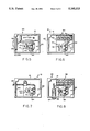
- FIG. 5 is a top view of the differential pressure control housing of FIG. 1 with the cover removed, and including an alarm according to this invention
- FIG. 6 is another top view of the differential pressure control housing of FIG. 1 with the cover removed, and including a terminal block structure according to the invention
- FIG. 7 is yet another top view of the differential pressure control housing of FIG. 1 with the cover removed (skeleton), and showing the lead wires thereof;
- FIG. 8 is another top view of the differential pressure control housing of FIG. 1 with the cover removed, and including an LED indicator (one or two indicators) according to this invention.
- a differential pressure control 10 is depicted generally in FIG. 1.
- the housing 12 that encases mechanism components comprises in this embodiment a 30% glass polyester (VALOX 865) that is molded and machined to include the various orifices for accepting the components.
- the housing 12 also includes a mounting base 14 with holes 16 for mounting the differential pressure control 10 in any desired location.
- the housing 12 defines a central chamber 18 having opposed high pressure and low pressure inlets 20 and 22, respectively, at its open ends that are adapted to carry connectors 24, 26 having threads or other means to which pressurized fluid lines (not shown) may be attached.
- the connectors 24, 26 are formed separately of a polysulfone compound (UDEL) and are secured to the housing 12 by screws 28 (See FIG. 2).
- Each connector 24 or 26 further includes a relatively small diameter (0.062 inch in this example) hole 30 for allowing pressurized fluid to enter the central chamber 18.
- a diaphragm 32 that in this example is formed of 0.005 inch thickness polyether material.
- the diaphragm 32 is secured in a sealed relationship relative to the chamber 18 between the housing 12 and an O-ring 34 disposed in an annular trough 36 about each of the connectors 24, 26.
- Each O-ring 34 seals the corresponding connector 24, 26 to the housing 12.
- each connector 24, 26 includes a flared opening 38 proximate the chamber 18 to facilitate a wide fluid contact surface for its diaphragm 32.
- Each O-ring 34 is composed of ethylene propylene according to this example.
- the chamber 18 is sized to carry a piston 40 therein that is further detailed in FIG. 3 and includes a through cut slot 42 for receiving a lever 44.
- the lever 44 is, itself, further depicted in FIG. 4 and is formed with a curved shoulder 46 and indentation 48 (shown in phantom) to engage a conforming edge 50 and domed protrusion 52 on the piston 40.
- the piston 40 snaps into the desired fixed position upon the lever 44 to form an integral assembly.
- the construction of both the lever 44 and piston 40 from glass filled polyester or similar resilient material facilitates a quick snap fit assembly of components in this example.
- the assembly of the lever 44 and piston 40 is disposed in the housing 12 to engage and pivot on a pin 53 in the lower portion 55 of the housing 12 between each of the diaphragms 32.
- the diameter of the piston 40 is sized smaller than that of the chamber 18 so that the piston's cylindrical wall at no time contacts the chamber's inner wall 56 while pivoting within the desired range of motion. As such a spacing 57 is shown between the piston and chamber in FIG. 1.
- the upper free end 58 of the lever 44 includes a hole 60 (See FIG. 4) carrying a plunger 62 for contacting the button 65 of a housing-mounted SPDT (submininature snap acting) microswitch 64.
- the plunger 62 may be mounted in the hole 60 via threads to allow calibration adjustment.
- the switch 64 is rated, in this example, for 3 amps at 125-250 VAC. It is positioned to be tripped or fully "pressed" when the lever 44 is pivoted to the extreme right in housing 12 as viewed in FIG. 1. Note that since the microswitch is a momentary contact type, the button 65 releases automatically as the lever plunger 62 withdraws from it. Otherwise a mechanical linkage would be required to operate the switch.
- the term "switch" should be taken to include, generally, a multiposition/multistate switch or a continuously variable control of electrical power or other influence in accordance with this invention.
- the diaphragms engage side walls 66 of the piston 40 to displace it.
- Each diaphragm 32 displaces toward its corresponding side wall 66 to exert force upon the piston in response to fluid pressure received through its respective inlet 20, 22.
- the diaphragms 32 thus push the piston 40 into an equilibrium position based upon the forces applied by the diaphragms and the resulting displacements.
- the right side 68 of the lever 44 (See FIGS. 1 and 4) includes a recess 70 for receiving a metallic spring 72 for normally imparting additional biasing force upon the lever 44 toward the high pressure inlet 20 and away from the microswitch button 65.
- the spring 72 provides a force balance where one source pressure is substantially less than the other.
- An adjusting screw 73 which may be made of glass filled polyester alters the load applied by spring 72. Tightening the screw 73 toward the spring increases force against the lever, while the screw loosening decreases that force. By varying the load imposed by spring 72, the user may vary the balance of high pressure versus low pressure required to allow the lever 44 to pivot and thereby trip the microswitch 64.
- the forces of both the spring 72 and the low pressure of inlet 22 determine the total pressure required at the high pressure inlet 20 to trip the switch 64.
- the balance of forces upon the lever 44 will cause it to displace and trip the switch 64.
- the actual amount of displacement, and hence, pressure differential, required to cause a state change of the switch depends upon the range of switch button 65 motion as well as the amount of additional spring 72 force present.
- the housing 12 further includes a pair of integrally formed opposing stops 74 and 76.
- the stops 74, 76 engage the upper free end 58 of the lever 44 to limit left and right pivotal displacement and prevent hyperextension that might damage the delicate piston/diaphragm structure.
- the lever 44 and stops 74, 76 are sized and positioned so that the lever 44 only moves far enough in either direction to allow the switch button 65 to move between its on/off positions.
- the response time and sensitivity of the differential pressure control 10 of this embodiment is maximized because the lever experiences minimal intermediate motion between switch states.
- the housing 12 includes a screw mounted sheet steel cover 78 and gasket 80 that seals the upper portion 82 of the housing 12 to prevent infiltration of fluids that may damage and corrode internal system components such as the microswitch 64.
- the switch 64 is connected to external devices (not shown) by lead wires 84 connected thereto (See FIGS. 1 and 7) that extend through a conduit hole 83 in the upper portion 82 of the housing 12.
- the hole may include a sealing conduit to support the wires 84 securely and prevent liquid infiltration into the housing.
- the upper portion 82 of the housing 12 further includes a battery (9 volt transistor radio dry cell in this example) 86 and an alarm 88 connected to the microswitch 64. If a pressure imbalance occurs, the microswitch 64 is tripped, sending current to the alarm 88 that alerts the operator.
- a piezoelectric alarm may be utilized according to this invention.
- the upper portion 82 of the housing may include a terminal strip 90 as depicted in the alternative embodiment 91 of FIG. 6.
- the microswitch 64 leads 97 are connected to the terminal strip 90. This allows other automatic devices to be controlled based upon the state of the switch via connections with the strip 90.
- the upper portion 82 of the housing 12 includes an LED indicator 94 in combination with a terminal strip 96 that allows direct reading of the switch state at its source.
- This arrangement indicates a go/no go (on/off) balance of pressures to the operator useful in process control and also facilitates quick testing of the differential pressure control of this embodiment 93 to ensure that it is functioning properly.
Abstract
Description
Claims (17)
Priority Applications (1)
| Application Number | Priority Date | Filing Date | Title |
|---|---|---|---|
| US07/704,033 US5140113A (en) | 1991-05-22 | 1991-05-22 | Differential pressure control switch with a pivoting actuating lever and a biasing spring sealed in a housing |
Applications Claiming Priority (1)
| Application Number | Priority Date | Filing Date | Title |
|---|---|---|---|
| US07/704,033 US5140113A (en) | 1991-05-22 | 1991-05-22 | Differential pressure control switch with a pivoting actuating lever and a biasing spring sealed in a housing |
Publications (1)
| Publication Number | Publication Date |
|---|---|
| US5140113A true US5140113A (en) | 1992-08-18 |
Family
ID=24827784
Family Applications (1)
| Application Number | Title | Priority Date | Filing Date |
|---|---|---|---|
| US07/704,033 Expired - Lifetime US5140113A (en) | 1991-05-22 | 1991-05-22 | Differential pressure control switch with a pivoting actuating lever and a biasing spring sealed in a housing |
Country Status (1)
| Country | Link |
|---|---|
| US (1) | US5140113A (en) |
Cited By (8)
| Publication number | Priority date | Publication date | Assignee | Title |
|---|---|---|---|---|
| US5659295A (en) * | 1995-12-11 | 1997-08-19 | Bendix-Atlantic Inflator Company | Sliding piston pressure sensing device |
| US5710401A (en) * | 1993-11-23 | 1998-01-20 | Sarcos Group | Volumetric pump/valve |
| US5931647A (en) * | 1993-11-23 | 1999-08-03 | Sarcos, Inc. | Volumetric pump with bi-directional piston seal |
| US6007310A (en) * | 1993-11-23 | 1999-12-28 | Sarcos, Lc | Volumetric pump with sterility seal |
| US6452122B1 (en) | 1999-03-31 | 2002-09-17 | Leroy Peter C. | Pressure sensing device |
| US6653583B1 (en) * | 2002-06-11 | 2003-11-25 | Asa Electronic Industry Co., Ltd. | Limit switch |
| US20060059995A1 (en) * | 1999-07-19 | 2006-03-23 | Donaldson Company, Inc. | Differential pressure gauge for filter |
| US20060250364A1 (en) * | 2005-05-09 | 2006-11-09 | Alex Gorbunov | Ergonomic computer mouse |
Citations (15)
| Publication number | Priority date | Publication date | Assignee | Title |
|---|---|---|---|---|
| US2680168A (en) * | 1952-07-07 | 1954-06-01 | Frank W Murphy | Safety switch |
| US2982830A (en) * | 1959-05-04 | 1961-05-02 | Square D Co | Switch mechanism |
| US3657501A (en) * | 1970-11-23 | 1972-04-18 | W E Anderson Inc | Pressure actuated device with concentric piston stem actuators |
| US3752942A (en) * | 1972-03-10 | 1973-08-14 | Laval Turbine | Differential pressure switch with pivoted one-piece rigid flat switch-actuating disc member captured between two rolling diaphragms |
| US3848517A (en) * | 1972-08-28 | 1974-11-19 | Nason Co | Pressure sensitive device for operating a switch or the like |
| US3985986A (en) * | 1974-10-24 | 1976-10-12 | Kelsey-Hayes Company | Differential pressure warning switch |
| US4081636A (en) * | 1976-03-03 | 1978-03-28 | Johnson Controls, Inc. | Differential pressure cutout switch |
| US4103124A (en) * | 1976-12-20 | 1978-07-25 | United Electric Controls Company | Plug-in pressure switch |
| US4206455A (en) * | 1978-06-09 | 1980-06-03 | Midland-Ross Corporation | Piston overtravel indicator |
| US4272959A (en) * | 1979-01-20 | 1981-06-16 | Nissan Motor Company, Limited | Diaphragm breakage condition detecting device for a pressure control device |
| US4288685A (en) * | 1979-03-12 | 1981-09-08 | Produtos Eletricos Corona Ltda. | Flow-activated resistance heater for water |
| US4503301A (en) * | 1983-03-24 | 1985-03-05 | American Standard Inc. | Differential fluid pressure switch |
| US4743716A (en) * | 1986-09-30 | 1988-05-10 | Kogyo Keiki Kabushiki Kaisha | Pressure sensor |
| US4804808A (en) * | 1986-03-25 | 1989-02-14 | Greg Di S. Greganti & C. S.A.S. | Pressure sensing device for tires of motor vehicles |
| US4951810A (en) * | 1988-07-11 | 1990-08-28 | Robertshaw Control Company | Fluid control device for electrical switch unit |
-
1991
- 1991-05-22 US US07/704,033 patent/US5140113A/en not_active Expired - Lifetime
Patent Citations (15)
| Publication number | Priority date | Publication date | Assignee | Title |
|---|---|---|---|---|
| US2680168A (en) * | 1952-07-07 | 1954-06-01 | Frank W Murphy | Safety switch |
| US2982830A (en) * | 1959-05-04 | 1961-05-02 | Square D Co | Switch mechanism |
| US3657501A (en) * | 1970-11-23 | 1972-04-18 | W E Anderson Inc | Pressure actuated device with concentric piston stem actuators |
| US3752942A (en) * | 1972-03-10 | 1973-08-14 | Laval Turbine | Differential pressure switch with pivoted one-piece rigid flat switch-actuating disc member captured between two rolling diaphragms |
| US3848517A (en) * | 1972-08-28 | 1974-11-19 | Nason Co | Pressure sensitive device for operating a switch or the like |
| US3985986A (en) * | 1974-10-24 | 1976-10-12 | Kelsey-Hayes Company | Differential pressure warning switch |
| US4081636A (en) * | 1976-03-03 | 1978-03-28 | Johnson Controls, Inc. | Differential pressure cutout switch |
| US4103124A (en) * | 1976-12-20 | 1978-07-25 | United Electric Controls Company | Plug-in pressure switch |
| US4206455A (en) * | 1978-06-09 | 1980-06-03 | Midland-Ross Corporation | Piston overtravel indicator |
| US4272959A (en) * | 1979-01-20 | 1981-06-16 | Nissan Motor Company, Limited | Diaphragm breakage condition detecting device for a pressure control device |
| US4288685A (en) * | 1979-03-12 | 1981-09-08 | Produtos Eletricos Corona Ltda. | Flow-activated resistance heater for water |
| US4503301A (en) * | 1983-03-24 | 1985-03-05 | American Standard Inc. | Differential fluid pressure switch |
| US4804808A (en) * | 1986-03-25 | 1989-02-14 | Greg Di S. Greganti & C. S.A.S. | Pressure sensing device for tires of motor vehicles |
| US4743716A (en) * | 1986-09-30 | 1988-05-10 | Kogyo Keiki Kabushiki Kaisha | Pressure sensor |
| US4951810A (en) * | 1988-07-11 | 1990-08-28 | Robertshaw Control Company | Fluid control device for electrical switch unit |
Cited By (10)
| Publication number | Priority date | Publication date | Assignee | Title |
|---|---|---|---|---|
| US5710401A (en) * | 1993-11-23 | 1998-01-20 | Sarcos Group | Volumetric pump/valve |
| US5931647A (en) * | 1993-11-23 | 1999-08-03 | Sarcos, Inc. | Volumetric pump with bi-directional piston seal |
| US5944495A (en) * | 1993-11-23 | 1999-08-31 | Sarcos, Lc | Volumetric pump actuator |
| US6007310A (en) * | 1993-11-23 | 1999-12-28 | Sarcos, Lc | Volumetric pump with sterility seal |
| US5659295A (en) * | 1995-12-11 | 1997-08-19 | Bendix-Atlantic Inflator Company | Sliding piston pressure sensing device |
| US6452122B1 (en) | 1999-03-31 | 2002-09-17 | Leroy Peter C. | Pressure sensing device |
| US20060059995A1 (en) * | 1999-07-19 | 2006-03-23 | Donaldson Company, Inc. | Differential pressure gauge for filter |
| US7886610B2 (en) | 1999-07-19 | 2011-02-15 | Donaldson Company, Inc. | Differential pressure gauge for filter |
| US6653583B1 (en) * | 2002-06-11 | 2003-11-25 | Asa Electronic Industry Co., Ltd. | Limit switch |
| US20060250364A1 (en) * | 2005-05-09 | 2006-11-09 | Alex Gorbunov | Ergonomic computer mouse |
Similar Documents
| Publication | Publication Date | Title |
|---|---|---|
| US2636093A (en) | Pressure switch | |
| US5140113A (en) | Differential pressure control switch with a pivoting actuating lever and a biasing spring sealed in a housing | |
| US5015808A (en) | Normally open pressure switch | |
| US3378656A (en) | Adjustment means for electrical switch | |
| US4081636A (en) | Differential pressure cutout switch | |
| CA2056462C (en) | In field settable differential pressure switch assembly for low fluid pressure applications | |
| US4272660A (en) | Vacuum operated switch | |
| US4631374A (en) | Diaphragm operated switch type bin level sensor | |
| EP0458494B1 (en) | Normally closed pressure responsive switch | |
| US6040536A (en) | Pressure responsive switch and method of making same | |
| US3335242A (en) | Condition responsive devices | |
| US5132500A (en) | Differential pressure switch with sealed contacts | |
| US4048455A (en) | Pressure switch with plural axes pivoted conduction plate | |
| US4172412A (en) | Fluid operated diaphragm assembly having a pair of like opposed diaphragms | |
| JPH0460287B2 (en) | ||
| US4541283A (en) | Pressure sensor | |
| US3864537A (en) | Pressure responsive apparatus including valve actuating means | |
| JPH02121220A (en) | Fluid pressure operation type switch | |
| US2916577A (en) | Fluid pressure responsive switch | |
| JPH06283081A (en) | Pressure-responsive electric switch | |
| US6633010B2 (en) | Compact, sealed pressure switch | |
| US5120915A (en) | Pressure-actuated pump control switch | |
| US5574265A (en) | Switch housing including extensible external actuator and improved terminal structure | |
| US4273976A (en) | Pressure responsive switch device | |
| US3038044A (en) | Pressure control apparatus |
Legal Events
| Date | Code | Title | Description |
|---|---|---|---|
| AS | Assignment |
Owner name: UNITED ELECTRIC CONTROLS COMPANY A MA CORPORATI Free format text: ASSIGNMENT OF ASSIGNORS INTEREST.;ASSIGNOR:MACHADO, JOHN S.;REEL/FRAME:005721/0177 Effective date: 19910520 |
|
| FEPP | Fee payment procedure |
Free format text: PAYOR NUMBER ASSIGNED (ORIGINAL EVENT CODE: ASPN); ENTITY STATUS OF PATENT OWNER: SMALL ENTITY |
|
| STCF | Information on status: patent grant |
Free format text: PATENTED CASE |
|
| FPAY | Fee payment |
Year of fee payment: 4 |
|
| FPAY | Fee payment |
Year of fee payment: 8 |
|
| FEPP | Fee payment procedure |
Free format text: PAYER NUMBER DE-ASSIGNED (ORIGINAL EVENT CODE: RMPN); ENTITY STATUS OF PATENT OWNER: SMALL ENTITY Free format text: PAYOR NUMBER ASSIGNED (ORIGINAL EVENT CODE: ASPN); ENTITY STATUS OF PATENT OWNER: SMALL ENTITY |
|
| FEPP | Fee payment procedure |
Free format text: PAYOR NUMBER ASSIGNED (ORIGINAL EVENT CODE: ASPN); ENTITY STATUS OF PATENT OWNER: SMALL ENTITY Free format text: PAYER NUMBER DE-ASSIGNED (ORIGINAL EVENT CODE: RMPN); ENTITY STATUS OF PATENT OWNER: SMALL ENTITY |
|
| FEPP | Fee payment procedure |
Free format text: PAYOR NUMBER ASSIGNED (ORIGINAL EVENT CODE: ASPN); ENTITY STATUS OF PATENT OWNER: SMALL ENTITY Free format text: PAYER NUMBER DE-ASSIGNED (ORIGINAL EVENT CODE: RMPN); ENTITY STATUS OF PATENT OWNER: SMALL ENTITY |
|
| FPAY | Fee payment |
Year of fee payment: 12 |