US4834603A - Stud and stud retaining fastener assembly - Google Patents
Stud and stud retaining fastener assembly Download PDFInfo
- Publication number
- US4834603A US4834603A US06/133,170 US13317087A US4834603A US 4834603 A US4834603 A US 4834603A US 13317087 A US13317087 A US 13317087A US 4834603 A US4834603 A US 4834603A
- Authority
- US
- United States
- Prior art keywords
- stud
- generally
- fastener
- edge
- blank
- Prior art date
- Legal status (The legal status is an assumption and is not a legal conclusion. Google has not performed a legal analysis and makes no representation as to the accuracy of the status listed.)
- Expired - Lifetime
Links
- 239000002184 metal Substances 0.000 claims abstract description 25
- 238000004080 punching Methods 0.000 claims abstract description 13
- 238000000034 method Methods 0.000 claims description 6
- 230000004323 axial length Effects 0.000 claims 1
- 230000014759 maintenance of location Effects 0.000 abstract description 3
- 238000010008 shearing Methods 0.000 abstract 1
- 230000000717 retained effect Effects 0.000 description 6
- 238000005336 cracking Methods 0.000 description 5
- 230000001788 irregular Effects 0.000 description 2
- 229910000760 Hardened steel Inorganic materials 0.000 description 1
- 230000015572 biosynthetic process Effects 0.000 description 1
- 239000000919 ceramic Substances 0.000 description 1
- 238000010276 construction Methods 0.000 description 1
- 230000008676 import Effects 0.000 description 1
- 238000004519 manufacturing process Methods 0.000 description 1
- 239000000463 material Substances 0.000 description 1
- 230000000149 penetrating effect Effects 0.000 description 1
- 238000005476 soldering Methods 0.000 description 1
- 229910001220 stainless steel Inorganic materials 0.000 description 1
- 239000010935 stainless steel Substances 0.000 description 1
Images
Classifications
-
- F—MECHANICAL ENGINEERING; LIGHTING; HEATING; WEAPONS; BLASTING
- F16—ENGINEERING ELEMENTS AND UNITS; GENERAL MEASURES FOR PRODUCING AND MAINTAINING EFFECTIVE FUNCTIONING OF MACHINES OR INSTALLATIONS; THERMAL INSULATION IN GENERAL
- F16B—DEVICES FOR FASTENING OR SECURING CONSTRUCTIONAL ELEMENTS OR MACHINE PARTS TOGETHER, e.g. NAILS, BOLTS, CIRCLIPS, CLAMPS, CLIPS OR WEDGES; JOINTS OR JOINTING
- F16B21/00—Means for preventing relative axial movement of a pin, spigot, shaft or the like and a member surrounding it; Stud-and-socket releasable fastenings
- F16B21/10—Means for preventing relative axial movement of a pin, spigot, shaft or the like and a member surrounding it; Stud-and-socket releasable fastenings by separate parts
- F16B21/20—Means for preventing relative axial movement of a pin, spigot, shaft or the like and a member surrounding it; Stud-and-socket releasable fastenings by separate parts for bolts or shafts without holes, grooves, or notches for locking members
-
- B—PERFORMING OPERATIONS; TRANSPORTING
- B21—MECHANICAL METAL-WORKING WITHOUT ESSENTIALLY REMOVING MATERIAL; PUNCHING METAL
- B21D—WORKING OR PROCESSING OF SHEET METAL OR METAL TUBES, RODS OR PROFILES WITHOUT ESSENTIALLY REMOVING MATERIAL; PUNCHING METAL
- B21D22/00—Shaping without cutting, by stamping, spinning, or deep-drawing
- B21D22/02—Stamping using rigid devices or tools
- B21D22/04—Stamping using rigid devices or tools for dimpling
-
- Y—GENERAL TAGGING OF NEW TECHNOLOGICAL DEVELOPMENTS; GENERAL TAGGING OF CROSS-SECTIONAL TECHNOLOGIES SPANNING OVER SEVERAL SECTIONS OF THE IPC; TECHNICAL SUBJECTS COVERED BY FORMER USPC CROSS-REFERENCE ART COLLECTIONS [XRACs] AND DIGESTS
- Y10—TECHNICAL SUBJECTS COVERED BY FORMER USPC
- Y10S—TECHNICAL SUBJECTS COVERED BY FORMER USPC CROSS-REFERENCE ART COLLECTIONS [XRACs] AND DIGESTS
- Y10S411/00—Expanded, threaded, driven, headed, tool-deformed, or locked-threaded fastener
- Y10S411/918—Threadless nut
Definitions
- This invention relates to one-piece, stamped sheet metal, push-on stud retainers and in particular relates to relatively thin walled, one-piece, stamped sheet metal push-on stud retainers having minimal transverse dimensions and utilizing the relatively smooth continuous edge of a punched or pierced hole as the stud retaining edge of the stud retaining aperture.
- One-piece, stamped sheet metal, thin walled stud retaining fasteners of the push-on type are well known in the prior art. Examples of such prior art devices may be seen by reference to U.S. Pat. Nos. 2,975,667, issued Mar. 21, 1961; 2,986,060, issued May 30, 1961; 3,032,807, issued May 8, 1962; and 3,108,371, issued Nov. 29, 1963. Many of the prior art devices were formed by punching or piercing an aperture into a sheet metal blank and then slotting or slitting the edges of the punched aperture to provide a stud retaining aperture having a plurality of stud retaining fingers.
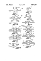
- FIG. 1A is a schematic cross sectional illustration of a hole punching or piercing operation in a fastener blank utilized to produce one type of prior art fasteners.
- FIG. 1B is a schematic cross sectional illustration of the dome shaped depression forming operation whereby the generally frusto-conical cross section of one type of the prior art fasteners was provided.
- FIG. 1C is a cross sectional illustration of the prior art fastener produced by the method illustrated in FIGS. 1A and 1B about to receive a stud.
- FIG. 1D is a cross sectional illustration of the prior art fastener of FIG. 1C as receiving and retaining a stud in the fully assembled position.
- FIG. 1E is a top view of another type of prior art fastener.
- FIG. 1F is a perspective view of the fastener of 1E utilized to retain a stud to a panel.
- FIG. 2 is a cross sectional schematic illustration of the first step in producing a fastener in accordance with the present invention, said first step comprising punching or piercing a hole into the fastener blank.
- FIG. 3 is a cross sectional schematic illustration of the second step in producing a fastener in accordance with the present invention, said second step comprises the forming of a generally dome shaped depression generally coaxial with the axis of the punched hole from the same side of the fastener blank as the hole punching operation.
- FIG. 4 is a cross sectional illustration of the fastener of the present invention about to receive a stud.
- FIG. 5 is a cross sectional illustration of the fastener of the present invention as retaining a stud in an apertured panel.
- FIG. 6 is a perspective view of the push-on stud retaining fastener of the present invention as utilized to retain a stud in an apertured panel.
- One piece, stamped, sheet metal, push-on stud retaining fasteners of the prior art and of the present invention both are, when utilized to retain a cross sectionally round stud, of a generally annular shape, having a generally centrally located annular stud retaining aperture, a generally frusto-conical annulus surrounding and defining the stud retaining aperture and a generally annular outer flange, the flange being generally perpendicular to the axis of the aperture.
- These devices are generally thin walled, that is, stamped from a relatively thin sheet of springy, hardened steel or stainless steel.
- the fasteners operate by frictionally gripping the outer edges of the stud.
- stud as used herein is intended to mean an elongated member of generally constant cross-section, such as a rod, shaft, bar, wire or the like.
- fasteners, and studs retained thereby, illustrated in this description will be shown as of a generally round crosssection. It is understood, however, that the fastener of the present invention is also intended and suitable for retention of studs having any cross-sectional shape.
- the fastener 10 of the present invention may be seen as utilized to secure a stud, such as a metallic or ceramic stud, extending from an electrical component or the like, to an apertured panel by reference to FIG. 6.
- a stud such as a metallic or ceramic stud
- the electrical lead of an electrical component is positively retained to a panel or a wire lead or terminal of an electrical component is retained to a panel prior to soldering thereof by use of the fastener of the present invention.
- the use of such fasteners is precision miniature and/or microminiature assembly requires that the transverse dimensions thereof, that is, the radius of the annular flanges, be minimized allowing the studs to be retained on closer centerlines.
- FIGS. 1A through 1F Two types of prior art one-piece, stamped, sheet metal, push-on stud retaining fasteners may be seen by reference to FIGS. 1A through 1F.
- the first type of prior art fastener that type utilizing the burred edge of a punched hole as the stud retaining edge of the stud retaining aperture, and the method of producing same, may be seen by reference to FIGS. 1A through 1D.
- the second type of prior art fastener that type using a slotted or slitted stud retaining aperture, may be seen by reference to FIGS. 1E and 1F.
- the prior art fastener 100 will receive and retain a stud S in the stud retaining aperture 102 thereof. Specifically, the stud S is frictionally and/or bitingly engaged by the stud retaining edge 104 of the stud retaining aperture 102.
- the stud retaining edge 104 is the burred edge of a punched hole as will be described below in greater detail.
- the prior art fastener 100 is formed by a method which is illustrated in FIGS. 1A and 1B.
- the fastener 100 is generally annular and is intended to receive and retain a stud S having a generally annular cross-section.
- the fastener 100 is produced by providing a generally annular sheet metal blank 106.
- the term "blank" as used herein is intended to include any portion of sheet metal suitable for formation into fasteners of the type described.
- the blank is placed in a blanking die, not shown, and a generally centrally located hole 108 is provided in the blank by punching out or piercing a generally annular section from the blank as is well known in the art.
- the punch contacts the blank from the top surface thereof and moves downwardly thru the metal blank to remove the annular section and then back upwardly as is well known in the stamping and blanking arts.
- the hole 108 is defined by an annular upper edge 110 and an annular lower edge 112.
- the upper edge 110 of the hole 108 that is, the edge on the surface first contacted by the punch and where the punch enters the metal, is relatively smooth and continuous, due to the compressing and compacting action of the punch, and is referred to as the smooth edge of the hole.
- the bottom edge 112 of the hole where the punch breaks through the metal is relatively rough and discontinuous and extends beyond the bottom surface 114 of the blank. This bottom edge is generally referred to as the "burred" edge of the hole.
- the burred edge is considerably rougher, more irregular, and less continuous than the smooth edge of the hole.
- the generally frusto-conical shape of the prior art fastener body 100 is then completed by a forming operation illustrated in FIG. 1B.
- a generally dome shaped impression 113 is formed in the blank from the bottom of the blank, or the opposite side from which the hole was punched from the blank.
- the generally dome shaped impression 113 is generally coaxial with the hole 108.
- the resultant fastener 100 comprises a generally centrally located stud receiving aperture 102, a generally frusto-conical annulus 116 and surrounding and defining the stud receiving aperture 102, and a generally annular outer flange 118.
- the stud retaining edge 104 that is, the radially innermost edge of the aperture 102, of the fastener is the burred edge 112 of the punched hole.
- FIGS. 1C and 1D illustrate a stud S being inserted into and then retained by, respectively, the stud retaining edge 104 of the stud retaining aperture 102 of the prior art fastener 100.
- FIGS. 1E and 1F Another form of prior art one-piece, stamped sheet metal, push-on stud retaining fastener is illustrated in FIGS. 1E and 1F.
- This type of fastener 200 utilizes a generally frusto-conically cross sectionally shaped stamped body having a slotted or slitted stud retaining aperture 202 therein.
- the stud retaining fastener 10 of the present invention comprises a generally resilient body 12 of relatively thin, stamped sheet metal.
- the body 12 comprises a frusto-conical annulus 14 defining a generally centrally located stud retaining aperture 16 and a radially outwardly extending annular flange 18 of transverse dimension 20.
- the stud retaining aperture 16 includes a radially inwardly extending stud retaining edge 22 which is adapted to engage and retain received studs.
- the stud receiving edge 22 of the fastener 10 is the relatively smooth continuous edge of a hole punched in the blank used to produce the fastener 10.
- the fastener 10 of the present invention is produced by providing a generally annular blank 24 and then punching or piercing a centrally located hole 26 therein.
- the blank 24 and the operation by which hole 26 is punched or pierced therein is similar to the operation in which blank 106 is provided with hole 108.
- the structure of the fastener 10 of the present invention allows the use of a blank having a smaller diameter.
- a forming tool is utilized to form a generally dome shaped impression 28 in the blank 24 which provides the fastener body 12 with a generally frusto-conical cross-sectional shape.
- the generally dome shaped impression 28 is coaxial with the axis of the punched hole 26. It is further noted that the forming tool strikes the blank 24 from the top side 30 thereof which is the same side that the punching tool strikes the blank.
- the relatively smooth continuous upper edge 32 of the punched hole becomes the stud engaging edge rather than the relatively irregular burred edge 34 which is at the bottom of the punched hole 26. Also, as the dome shaped impression is formed, the relatively smooth continuous upper edge 32 is stretched which produces a strong sharp edge 32.
- FIGS. 4 and 5 illustrate the fastener 10 of the present invention as about to receive and as assembled to a stud S, respectively, to retain the stud S to an apertured panel P.
Abstract
Description
Claims (1)
Priority Applications (1)
| Application Number | Priority Date | Filing Date | Title |
|---|---|---|---|
| US06/133,170 US4834603A (en) | 1977-05-03 | 1987-12-11 | Stud and stud retaining fastener assembly |
Applications Claiming Priority (3)
| Application Number | Priority Date | Filing Date | Title |
|---|---|---|---|
| US79333877A | 1977-05-03 | 1977-05-03 | |
| US1317387A | 1987-02-08 | 1987-02-08 | |
| US06/133,170 US4834603A (en) | 1977-05-03 | 1987-12-11 | Stud and stud retaining fastener assembly |
Related Parent Applications (1)
| Application Number | Title | Priority Date | Filing Date |
|---|---|---|---|
| US1317387A Continuation | 1977-05-03 | 1987-02-08 |
Publications (1)
| Publication Number | Publication Date |
|---|---|
| US4834603A true US4834603A (en) | 1989-05-30 |
Family
ID=27359796
Family Applications (1)
| Application Number | Title | Priority Date | Filing Date |
|---|---|---|---|
| US06/133,170 Expired - Lifetime US4834603A (en) | 1977-05-03 | 1987-12-11 | Stud and stud retaining fastener assembly |
Country Status (1)
| Country | Link |
|---|---|
| US (1) | US4834603A (en) |
Cited By (25)
| Publication number | Priority date | Publication date | Assignee | Title |
|---|---|---|---|---|
| US5007781A (en) * | 1990-09-10 | 1991-04-16 | General Dynamics Corporation, Convair Division | Tapered split-bushing fastener |
| US5215660A (en) * | 1992-01-29 | 1993-06-01 | Parker Hannifin Corporation | Filter drier for refrigeration system |
| US5449258A (en) * | 1993-10-26 | 1995-09-12 | Itt Corporation | Retainer clip and shaft fastener apparatus and method |
| US5524159A (en) * | 1994-11-04 | 1996-06-04 | The Whitaker Corporation | Fiber optic connector |
| US5532669A (en) * | 1992-11-27 | 1996-07-02 | Hokuriku Electric Industry Co., Ltd. | Terminal for high-voltage variable resistor |
| US5546280A (en) * | 1993-12-28 | 1996-08-13 | Hokuriku Electric Industry Co., Ltd. | Electronic component with soldering-less terminal structure |
| US5577144A (en) * | 1995-05-30 | 1996-11-19 | The Whitaker Corporation | Fiber optic connector |
| WO1997001466A2 (en) * | 1995-06-29 | 1997-01-16 | Itt Automotive Europe Gmbh | Mechanism housing |
| US5625731A (en) * | 1994-12-06 | 1997-04-29 | The Whitaker Corporation | Process for assembling an optical fiber connector |
| US5735171A (en) * | 1993-10-26 | 1998-04-07 | Itt Corporation | Pivot joint with retainer clip |
| US5794394A (en) * | 1997-03-10 | 1998-08-18 | Bill; Joseph A. | Anchor bolt centering device |
| US6125506A (en) * | 1998-09-11 | 2000-10-03 | Martin Door Manufacturing, Inc. | Shield apparatus and support track and method for a support roller of a sectional door |
| DE19949369A1 (en) * | 1999-10-13 | 2001-04-19 | Bayerische Motoren Werke Ag | Device for fixing cladding part to wall element; has bolt projecting inside cladding part to fit in fixing opening in wall element and secured by spring washer that expands to fit on bolt |
| US6227281B1 (en) | 1998-09-11 | 2001-05-08 | Martin Door Manufacturing, Inc. | Sectional door with roller shield apparatus |
| US6419184B1 (en) * | 2000-06-01 | 2002-07-16 | J. L. Clark, Inc. | Wooden spool held together with novel tie rod assembly and method of assembling the same between a pair of dies |
| US6540003B1 (en) | 1998-09-11 | 2003-04-01 | Martin Door Manufacturing, Inc. | Sectional door with roller shield apparatus |
| US6588169B2 (en) | 2000-09-25 | 2003-07-08 | Phillip T. Sarver | Universal mounting plate |
| US20050162776A1 (en) * | 2004-01-28 | 2005-07-28 | Samsung Electronics Co. Ltd. | Disk clamping apparatus and method for hard disk drive and hard disk drive with the same |
| US20050213256A1 (en) * | 2004-03-29 | 2005-09-29 | Dexter David D | Snap ring with debris-reducing cross-sectional profile |
| US20130323547A1 (en) * | 2012-05-25 | 2013-12-05 | Komatsulite Mfg. Co., Ltd. | Breaker, safety circuit with breaker and secondary battery with breaker |
| US20150098311A1 (en) * | 2013-10-09 | 2015-04-09 | Nivarox-Far S.A. | Assembly system utilizing a flat, elastic locking element |
| US20150253733A1 (en) * | 2014-03-05 | 2015-09-10 | Nivarox-Far S.A. | Balance spring intended to be clamped by a resilient washer |
| US20200173485A1 (en) * | 2018-12-03 | 2020-06-04 | Saint-Gobain Performance Plastics Pampus Gmbh | Push-on fastener, assembly, and method of making and using the same |
| US10933439B2 (en) | 2017-10-25 | 2021-03-02 | The Wooster Brush Company | Paint roller frame and cage assembly and method of manufacturing |
| US20210172643A1 (en) * | 2019-12-05 | 2021-06-10 | AR Developing, LLC | Hvac duct connection system and flange |
Citations (6)
| Publication number | Priority date | Publication date | Assignee | Title |
|---|---|---|---|---|
| US1460749A (en) * | 1921-03-23 | 1923-07-03 | Link Belt Co | Process for securing wrist pins for chain links |
| US1675277A (en) * | 1924-06-12 | 1928-06-26 | Mcbee Binder Company | Clutch for binders |
| US1752982A (en) * | 1926-07-06 | 1930-04-01 | Bassick Co | Method of producing spring rings |
| US2831388A (en) * | 1953-11-23 | 1958-04-22 | Prestole Corp | Apertured screw receiving deformity in sheet metal |
| US3108371A (en) * | 1959-11-16 | 1963-10-29 | Bishop & Babcock Corp | Method of making sheet metal fastener |
| US3481381A (en) * | 1968-09-05 | 1969-12-02 | Robert H Black | Lockwasher |
-
1987
- 1987-12-11 US US06/133,170 patent/US4834603A/en not_active Expired - Lifetime
Patent Citations (6)
| Publication number | Priority date | Publication date | Assignee | Title |
|---|---|---|---|---|
| US1460749A (en) * | 1921-03-23 | 1923-07-03 | Link Belt Co | Process for securing wrist pins for chain links |
| US1675277A (en) * | 1924-06-12 | 1928-06-26 | Mcbee Binder Company | Clutch for binders |
| US1752982A (en) * | 1926-07-06 | 1930-04-01 | Bassick Co | Method of producing spring rings |
| US2831388A (en) * | 1953-11-23 | 1958-04-22 | Prestole Corp | Apertured screw receiving deformity in sheet metal |
| US3108371A (en) * | 1959-11-16 | 1963-10-29 | Bishop & Babcock Corp | Method of making sheet metal fastener |
| US3481381A (en) * | 1968-09-05 | 1969-12-02 | Robert H Black | Lockwasher |
Cited By (32)
| Publication number | Priority date | Publication date | Assignee | Title |
|---|---|---|---|---|
| US5007781A (en) * | 1990-09-10 | 1991-04-16 | General Dynamics Corporation, Convair Division | Tapered split-bushing fastener |
| US5215660A (en) * | 1992-01-29 | 1993-06-01 | Parker Hannifin Corporation | Filter drier for refrigeration system |
| US5532669A (en) * | 1992-11-27 | 1996-07-02 | Hokuriku Electric Industry Co., Ltd. | Terminal for high-voltage variable resistor |
| US5449258A (en) * | 1993-10-26 | 1995-09-12 | Itt Corporation | Retainer clip and shaft fastener apparatus and method |
| US5735171A (en) * | 1993-10-26 | 1998-04-07 | Itt Corporation | Pivot joint with retainer clip |
| US5546280A (en) * | 1993-12-28 | 1996-08-13 | Hokuriku Electric Industry Co., Ltd. | Electronic component with soldering-less terminal structure |
| US5524159A (en) * | 1994-11-04 | 1996-06-04 | The Whitaker Corporation | Fiber optic connector |
| US5724723A (en) * | 1994-12-06 | 1998-03-10 | The Whitaker Corporation | Apparatus for assembling an optical fiber connector |
| US5625731A (en) * | 1994-12-06 | 1997-04-29 | The Whitaker Corporation | Process for assembling an optical fiber connector |
| US5577144A (en) * | 1995-05-30 | 1996-11-19 | The Whitaker Corporation | Fiber optic connector |
| WO1997001466A3 (en) * | 1995-06-29 | 1997-03-13 | Teves Gmbh Alfred | Mechanism housing |
| WO1997001466A2 (en) * | 1995-06-29 | 1997-01-16 | Itt Automotive Europe Gmbh | Mechanism housing |
| US5794394A (en) * | 1997-03-10 | 1998-08-18 | Bill; Joseph A. | Anchor bolt centering device |
| US6125506A (en) * | 1998-09-11 | 2000-10-03 | Martin Door Manufacturing, Inc. | Shield apparatus and support track and method for a support roller of a sectional door |
| US6227281B1 (en) | 1998-09-11 | 2001-05-08 | Martin Door Manufacturing, Inc. | Sectional door with roller shield apparatus |
| US6540003B1 (en) | 1998-09-11 | 2003-04-01 | Martin Door Manufacturing, Inc. | Sectional door with roller shield apparatus |
| DE19949369C2 (en) * | 1999-10-13 | 2003-07-03 | Bayerische Motoren Werke Ag | Attachment of a trim part to a wall element |
| DE19949369A1 (en) * | 1999-10-13 | 2001-04-19 | Bayerische Motoren Werke Ag | Device for fixing cladding part to wall element; has bolt projecting inside cladding part to fit in fixing opening in wall element and secured by spring washer that expands to fit on bolt |
| US6419184B1 (en) * | 2000-06-01 | 2002-07-16 | J. L. Clark, Inc. | Wooden spool held together with novel tie rod assembly and method of assembling the same between a pair of dies |
| US6588169B2 (en) | 2000-09-25 | 2003-07-08 | Phillip T. Sarver | Universal mounting plate |
| US20050162776A1 (en) * | 2004-01-28 | 2005-07-28 | Samsung Electronics Co. Ltd. | Disk clamping apparatus and method for hard disk drive and hard disk drive with the same |
| US7589935B2 (en) * | 2004-01-28 | 2009-09-15 | Samsung Electronics Co., Ltd. | Disk clamping apparatus for hard disk drive and hard disk drive with the same |
| US20050213256A1 (en) * | 2004-03-29 | 2005-09-29 | Dexter David D | Snap ring with debris-reducing cross-sectional profile |
| US20130323547A1 (en) * | 2012-05-25 | 2013-12-05 | Komatsulite Mfg. Co., Ltd. | Breaker, safety circuit with breaker and secondary battery with breaker |
| US9671755B2 (en) * | 2013-10-09 | 2017-06-06 | Nivarox-Far S.A. | Assembly system utilizing a flat, elastic locking element |
| US20150098311A1 (en) * | 2013-10-09 | 2015-04-09 | Nivarox-Far S.A. | Assembly system utilizing a flat, elastic locking element |
| US20150253733A1 (en) * | 2014-03-05 | 2015-09-10 | Nivarox-Far S.A. | Balance spring intended to be clamped by a resilient washer |
| US9983548B2 (en) * | 2014-03-05 | 2018-05-29 | Nivarox-Far S.A. | Balance spring intended to be clamped by a resilient washer |
| US10933439B2 (en) | 2017-10-25 | 2021-03-02 | The Wooster Brush Company | Paint roller frame and cage assembly and method of manufacturing |
| US20200173485A1 (en) * | 2018-12-03 | 2020-06-04 | Saint-Gobain Performance Plastics Pampus Gmbh | Push-on fastener, assembly, and method of making and using the same |
| US20210172643A1 (en) * | 2019-12-05 | 2021-06-10 | AR Developing, LLC | Hvac duct connection system and flange |
| US11768009B2 (en) * | 2019-12-05 | 2023-09-26 | AR Developing, LLC | HVAC duct connection system and flange |
Similar Documents
| Publication | Publication Date | Title |
|---|---|---|
| US4834603A (en) | Stud and stud retaining fastener assembly | |
| US3276499A (en) | Flush-driven self-piercing and clinching nut and method of securing to a member | |
| US4543701A (en) | Method of attaching a fastener to a panel | |
| US3234987A (en) | Self-piercing nut with attaching flange | |
| JP2860917B2 (en) | Method of attaching self-piercing rivet fastener to panel and die member for attaching self-piercing rivet fastener to panel | |
| US2846701A (en) | Method of forming a sheet metal lock nut | |
| JPS5935732B2 (en) | Die assembly for grappling and engaging the tightener with the panel | |
| JPS63186019A (en) | Method of fixing fastener to sheet material and fastener used for said method | |
| US3108371A (en) | Method of making sheet metal fastener | |
| JPH0427402B2 (en) | ||
| US3244212A (en) | Retractable threaded fastener | |
| JPH0462819B2 (en) | ||
| US4385431A (en) | Method of securing a stud to an apertured panel | |
| US4525912A (en) | Pierce nut and a back-up die used in combination therewith | |
| US4159552A (en) | Method of manufacturing a barrel nut | |
| US7013550B2 (en) | Method of making self-piercing nuts | |
| US2216878A (en) | Method of forming detents | |
| CA1134652A (en) | Stud retaining fastener and method for producing same | |
| US2592129A (en) | Method of making a self-locking nut | |
| US3494168A (en) | Forming tool | |
| JPS5933464B2 (en) | Manufacturing method of hollow studs for star clinch | |
| CA1121624A (en) | Removable stud retaining fastener | |
| US11578751B2 (en) | Component assembly comprising a component and an element having a head part and a collar arranged at one side of the head part as well as manufacturing methods | |
| US3460234A (en) | Method of installing a terminal to a plate | |
| US3923089A (en) | Nut and panel assembly |
Legal Events
| Date | Code | Title | Description |
|---|---|---|---|
| FEPP | Fee payment procedure |
Free format text: PAYOR NUMBER ASSIGNED (ORIGINAL EVENT CODE: ASPN); ENTITY STATUS OF PATENT OWNER: LARGE ENTITY |
|
| STCF | Information on status: patent grant |
Free format text: PATENTED CASE |
|
| FEPP | Fee payment procedure |
Free format text: PAYER NUMBER DE-ASSIGNED (ORIGINAL EVENT CODE: RMPN); ENTITY STATUS OF PATENT OWNER: LARGE ENTITY Free format text: PAYOR NUMBER ASSIGNED (ORIGINAL EVENT CODE: ASPN); ENTITY STATUS OF PATENT OWNER: LARGE ENTITY |
|
| FPAY | Fee payment |
Year of fee payment: 4 |
|
| FPAY | Fee payment |
Year of fee payment: 8 |
|
| AS | Assignment |
Owner name: BANKBOSTON, N.A., AS AGENT, MASSACHUSETTS Free format text: AMENDED AND RESTATED PATENT COLLATERAL ASSIGNMENT AND SECURITY AGREEMENT;ASSIGNORS:TRANSTECHNOLOGY CORPORATION;SEEGER INC.;NORCO, INC.;AND OTHERS;REEL/FRAME:010628/0792 Effective date: 19990831 |
|
| FPAY | Fee payment |
Year of fee payment: 12 |
|
| AS | Assignment |
Owner name: TRANS TECHNOLOGY ENGINEERED COMPONENTS, LLC, OHIO Free format text: ASSIGNMENT OF ASSIGNORS INTEREST;ASSIGNOR:EATON CORPORATION;REEL/FRAME:011260/0723 Effective date: 19990831 |
|
| AS | Assignment |
Owner name: NATIONAL CITY BANK, AS AGENT, OHIO Free format text: ASSIGNMENT OF ASSIGNORS INTEREST;ASSIGNOR:TRANSTECHNOLOGY ENGINEERED COMPONENTS, LLC;REEL/FRAME:012707/0266 Effective date: 20011205 Owner name: TRANSTECHNOLOGY CORPORATION, NEW JERSEY Free format text: CORECTIVE ASSIGNMENT OT CORRECT COVERSHEET ID # 102011619.;ASSIGNOR:FLEET NATIONAL BANK (FORMERLY KNOWN AS BANKBOSTON, N.A.);REEL/FRAME:012946/0412 Effective date: 20011206 Owner name: SEEGER INC., NEW JERSEY Free format text: CORECTIVE ASSIGNMENT OT CORRECT COVERSHEET ID # 102011619.;ASSIGNOR:FLEET NATIONAL BANK (FORMERLY KNOWN AS BANKBOSTON, N.A.);REEL/FRAME:012946/0412 Effective date: 20011206 Owner name: TCR CORPORATION, MINNESOTA Free format text: CORECTIVE ASSIGNMENT OT CORRECT COVERSHEET ID # 102011619.;ASSIGNOR:FLEET NATIONAL BANK (FORMERLY KNOWN AS BANKBOSTON, N.A.);REEL/FRAME:012946/0412 Effective date: 20011206 Owner name: AEROSPACE RIVETS, CALIFORNIA Free format text: CORECTIVE ASSIGNMENT OT CORRECT COVERSHEET ID # 102011619.;ASSIGNOR:FLEET NATIONAL BANK (FORMERLY KNOWN AS BANKBOSTON, N.A.);REEL/FRAME:012946/0412 Effective date: 20011206 Owner name: NORCO, INC., CONNECTICUT Free format text: CORECTIVE ASSIGNMENT OT CORRECT COVERSHEET ID # 102011619.;ASSIGNOR:FLEET NATIONAL BANK (FORMERLY KNOWN AS BANKBOSTON, N.A.);REEL/FRAME:012946/0412 Effective date: 20011206 Owner name: TRANSTECHNOLOGY ENGINEERED COMPONENTS, OHIO Free format text: CORECTIVE ASSIGNMENT OT CORRECT COVERSHEET ID # 102011619.;ASSIGNOR:FLEET NATIONAL BANK (FORMERLY KNOWN AS BANKBOSTON, N.A.);REEL/FRAME:012946/0412 Effective date: 20011206 Owner name: TRANSTECHNOLOGY CANADA CORPORATION, CANADA Free format text: CORECTIVE ASSIGNMENT OT CORRECT COVERSHEET ID # 102011619.;ASSIGNOR:FLEET NATIONAL BANK (FORMERLY KNOWN AS BANKBOSTON, N.A.);REEL/FRAME:012946/0412 Effective date: 20011206 |
|
| AS | Assignment |
Owner name: TINNERMAN PALNUT ENGINEERED PRODUCTS, LLC, OHIO Free format text: RELEASE AND REASSIGNMENT;ASSIGNOR:NATIONAL CITY BANK, AS AGENT;REEL/FRAME:014964/0265 Effective date: 20040204 |
|
| AS | Assignment |
Owner name: ANTARES CAPITAL CORPORATION, AS AGENT, ILLINOIS Free format text: SECURITY AGREEMENT;ASSIGNOR:TINNERMAN PALNUT ENGINEERED PRODUCTS, LLC;REEL/FRAME:014990/0418 Effective date: 20040206 |
|
| AS | Assignment |
Owner name: KTIN ACQUISITIONS, LLC, NEW YORK Free format text: MERGER;ASSIGNOR:TRANS TECHNOLOGY ENGINEERED COMPONENTS, LLC;REEL/FRAME:014499/0743 Effective date: 20011205 Owner name: TINNERMAN PALNUT ENGINEERED PRODUCTS, LLC., OHIO Free format text: CHANGE OF NAME;ASSIGNOR:KTIN, ACQUISTIONS, LLC;REEL/FRAME:014499/0747 Effective date: 20011205 Owner name: TRANS TECHNOLOGY ENGINEERED COMPONENTS, LLC, OHIO Free format text: ASSIGNMENT OF ASSIGNORS INTEREST;ASSIGNOR:NATIONAL CITY BANK;REEL/FRAME:014506/0130 Effective date: 20040407 |
|
| AS | Assignment |
Owner name: BNP PARIBAS, AS ADMINISTRATIVE AGENT UNDER CREDIT Free format text: ASSIGNMENT OF ASSIGNORS INTEREST;ASSIGNOR:TINNERMAN PALNUT ENGINEERED PRODUCTS, LLC;REEL/FRAME:015320/0321 Effective date: 20041101 Owner name: TINNERMAN PALNUT ENGINEERED PRODUCTS, LLC, OHIO Free format text: RELEASE OF SECURITY INTEREST;ASSIGNOR:ANTARES CAPITAL CORPORATION, AS AGENT;REEL/FRAME:015328/0066 Effective date: 20041029 |
|
| AS | Assignment |
Owner name: BNP PARIBAS, AS ADMINISTRATIVE AGENT UNDER TERM LO Free format text: ASSIGNMENT OF ASSIGNORS INTEREST;ASSIGNOR:TINNERMAN PALNUT ENGINEERED PRODUCTS, LLC;REEL/FRAME:015320/0951 Effective date: 20041101 |
|
| AS | Assignment |
Owner name: TINNERMAN PALNUT ENGINEERED PRODUCTS, INC., OHIO Free format text: RELEASE BY SECURED PARTY;ASSIGNOR:BNP PARIBAS;REEL/FRAME:023438/0013 Effective date: 20091028 |