US4781167A - Compound bow with adjustable tension cable anchor - Google Patents
Compound bow with adjustable tension cable anchor Download PDFInfo
- Publication number
- US4781167A US4781167A US07/020,753 US2075387A US4781167A US 4781167 A US4781167 A US 4781167A US 2075387 A US2075387 A US 2075387A US 4781167 A US4781167 A US 4781167A
- Authority
- US
- United States
- Prior art keywords
- yoke
- cable
- tension
- tension cable
- anchor
- Prior art date
- Legal status (The legal status is an assumption and is not a legal conclusion. Google has not performed a legal analysis and makes no representation as to the accuracy of the status listed.)
- Expired - Fee Related
Links
Images


Classifications
-
- F—MECHANICAL ENGINEERING; LIGHTING; HEATING; WEAPONS; BLASTING
- F41—WEAPONS
- F41B—WEAPONS FOR PROJECTING MISSILES WITHOUT USE OF EXPLOSIVE OR COMBUSTIBLE PROPELLANT CHARGE; WEAPONS NOT OTHERWISE PROVIDED FOR
- F41B5/00—Bows; Crossbows
- F41B5/10—Compound bows
-
- Y—GENERAL TAGGING OF NEW TECHNOLOGICAL DEVELOPMENTS; GENERAL TAGGING OF CROSS-SECTIONAL TECHNOLOGIES SPANNING OVER SEVERAL SECTIONS OF THE IPC; TECHNICAL SUBJECTS COVERED BY FORMER USPC CROSS-REFERENCE ART COLLECTIONS [XRACs] AND DIGESTS
- Y10—TECHNICAL SUBJECTS COVERED BY FORMER USPC
- Y10T—TECHNICAL SUBJECTS COVERED BY FORMER US CLASSIFICATION
- Y10T24/00—Buckles, buttons, clasps, etc.
- Y10T24/21—Strap tighteners
- Y10T24/2164—Midline
Definitions
- This invention relates generally to archery bows, and more particularly to compound bows and tension cable anchors for compound bows.
- Compound archery bows have become increasingly popular for hunting and target shooting in recent years. These bows use tension cables which extend over eccentric pulleys revolvably mounted to the bow limbs to provide a mechanical advantage during the drawback and release of a bow string.
- the compound bow cable includes a central, or bow string, portion for reception of the arrow.
- a pair of tension cable portions are connected to the ends of the bow string and extend over the eccentrically mounted pulleys.
- the tension cable portions typically cross one another between the limbs and attach to the bow limb opposite the pulley over which the respective tension cable portion extends.
- maximum energy is stored in the limbs without requiring maximum force to be applied to the bow string to hold it at the full draw position. This permits the archer to maintain aim on his target prior to release for a longer time and without undue strain for producing a better shot.
- the 4,440,142 patent to Simonds discloses a yoke cable connected at both its ends to a pulley axle which rotatably supports an eccentrically mounted pulley.
- the cable extends about a perimetric edge portion of a disk-like yoke for securing the disk relative to the axle.
- a plurality of attachment grooves are formed in the disk which are disposed at varying distances from the disk center.
- An end of the tension cable extends through the center of the disk and is received by any one of these attachment portions, and is looped back to itself and fixedly secured by a clasp or sleeve-like member.
- Such an anchoring device enables the tension in the tension cable to be adjusted by changing which of the attachment portions in which the loop in the tension cable is received.
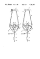
- FIG. 1 is a side view of one embodiment of a compound bow employing a tension cable anchor in accordance with the invention
- FIG. 2 is an enlarged front view of an adjustable tension cable anchor used in the compound bow shown in FIG. 1;
- FIG. 3 is an enlarged front view of the adjustable tension cable anchor shown in an operative position displaced slightly from that shown in FIG. 2;
- FIG. 4 is a front view of a body portion of the adjustable tension cable anchor of FIG. 2;
- FIG. 5 is a side view of the body of FIG. 4;
- FIG. 6 is a top view of the body of FIG. 4;
- FIG. 7 is a front view of a yoke cable receiving member employed in the adjustable tension cable anchor of FIG. 2;
- FIG. 8 is a side view of the yoke cable receiving member of FIG. 7;
- FIG. 9 is a top view of the yoke cable receiving member of FIG. 7;
- FIG. 10 is a front view of an alternate embodiment of an adjustable tension cable anchor in accordance with the invention.
- FIG. 11 is a side view of the adjustable anchor of FIG. 10.
- a compound bow 10 includes a center handle section 12 which supports upper and lower limbs 14, 16, respectively.
- Eccentric pulley assemblies 18 are rotatably mounted adjacent the outermost ends of upper and lower limbs 14, 16 by pulley axles 38.
- Bow 10 includes a central cable portion, or bow string 20, which is secured at both ends to a pair of tension cables 22, 24.
- Tension cables 22, 24 extend from the ends of bow string 20 over respective eccentric pulley assemblies 18 to the opposite bow limb where each is there secured by means of an adjustable anchoring assembly 26.
- the inside portions of the tension cables are held adjacent one another by means of button assemblies 28 which engage the tension cables adjacent anchoring assemblies 26 for keeping such cables collected and separated from bow string portion 20.
- Compound bow 10 further includes a cable guard 30 which maintains collected tension cables 22, 24 slightly sideways further separating the cables from bow string 20.
- Adjustable cable anchoring assembly 26 is also of course usable without the inclusion of buttons 28 and cable guard 30.
- Anchor 26 in accordance with the invention is illustrated in the form of a yoke anchor.
- Anchor 26 includes a body 32 which movably receives a half disk-shaped yoke cable receiving member 34.
- Yoke cable receiving member 34 is adapted for receiving a yoke cable 36 about its outer perimetric edge 54.
- the ends of yoke cable 36 are anchored to pulley axle 38 by means of clasps or axle hangers 39.
- Tension cable 24, as shown, is looped through the lower portion of body 32 and secured back to itself by swage clasps 41. Accordingly, anchor 26 serves to secure or anchor the end of tension cable 24 operably to the compound bow limb. Adjustment means are provided for selectively varying the position of yoke cable receiving member 34 and body 32 relative to one another for adjusting the tension in tension cable 24.
- body 32 is generally triangular in shape having first and second ends 33, 35 respectively, and a centrally disposed cavity 40.
- Cavity 40 is adapted for slidably receiving yoke cable receiving member 34 therein.
- the upper and lower-most extents of cavity 40 terminate in horizontal surfaces 42, 43 respectively.
- a threaded hole 44 is formed in first end 33 of body 32 and extends inwardly to upper surface 42.
- An adjustment element in the form of a set screw 46 is threadingly received by threaded hole 44 for engaging yoke cable receiving member 34 to enable its position within cavity 40 to be selectively varied, as will be more fully described below.
- Body 32 further includes a pair of opposing upper side edge grooves 48 extending from upper cavity surface 42 along outer side surfaces to first end 33 of body 32 for receiving yoke cable 36.
- a grooved portion 50 is formed in the lower portion or second end 35 of body 32 and extends upwardly to central cavity 40. Groove 50 serves to receive an intermediate portion of tension cable 24 in the form of a loop 52 formed in the end of tension cable 24. Accordingly, groove 50 functions as a tension cable receiving means for enabling a tension cable to be secured to body 32.
- the yoke cable receiving member 34 is substantially semi-circular in shape having an arcuate first perimetric edge portion 54 terminating at two generally diametrically opposed locations 56, 58.
- Perimetric edge 54 includes a yoke cable receiving groove 64.
- a second perimetric edge portion 60 extends between diametrically opposed locations 56, 58.
- a recess 62 is formed in the center of second perimetric edge 60 and serves to receive set screw 46.
- set screw 46 includes an innermost end 66 adapted to engage recess 62 of second perimetric edge 60 on yoke cable receiving member 34.
- second perimetric edge 60 of yoke cable receiving member 34 will bear against upper cavity surface 42.
- the innermost end 66 of the set screw will bear against an inner surface in recess 62 of yoke cable receiving member 34 causing second perimetric edge 60 and surface 42 to be displaced from one another.
- the degree of displacement can be varied by the amount with which set screw 46 is inwardly threaded into opening 40 on body 32. Since yoke cable 36 is received about member 34 and tension cable 24 is received by body 32, such movement causes tension cable 24 to be moved with respect to the bow limb enabling its tension to be varied.
- FIGS. 2 and 3 illustrate alternate positionings of body 32 and yoke cable receiving member 34 relative to one another providing different tensions in tension cable 24.
- Indicia means can be provided for indicating the position of yoke cable receiving member 34 relative to body 32 to provide an indication of tension in cable 24.
- Such indicia means is shown in the form of a plurality of markings 68 formed in one or both of the opposing faces of yoke cable receiving member 34. Such markings align with a central straight surface 45 in body 32 to provide an indication of the position yoke cable receiving member 34 relative to body 32.
- the set screw adjustment enables the tension in the tension cables to be adjusted on a compound bow without releasing the tension in such cables.
- Prior art devices generally require some form of tension release prior to adjusting tension.
- the use of a set screw enables a nearly infinite number of tension adjustments to be made by merely varying the degree with which the set screw is turned.
- Such features also provide significant advantages to manufacturers of compound bows.
- one of the critical features in the manufacturing of compound bows is the tuning of the bows to assure that both the upper and lower eccentrically mounted pulley assemblies revolve through the over center point at precisely the same moment.
- a compound bow employing a pair of anchors in accordance with the invention will enable the bow assembler to rapidly produce this desired affect by making minor adjustments to either of the anchors as necessary without having to disassemble the bow.
- Anchor 70 is similar to anchor 26 in that it is comprised of a yoke structure. Anchor 70 employs different tension cable receiving means than that employed by the body of yoke anchor 26.
- Anchor 70 includes a body 132 having a generally centrally disposed cavity 140 which receives a yoke cable receiving member 134.
- a clamping apparatus 72 is integrally formed as part of body 132 for securing a tension cable 24 to the anchor.
- Clamping apparatus 72 is preferably reusable and integrally formed in the body.
- Clamping apparatus 72 includes a pair of passageways 74, 76 which extend into the second end 135 of body 132 for receiving tension cable 24.
- Passageways 74, 76 diverge from one another towards centrally disposed cavity 140.
- An intermediate portion of tension cable 24 is adapted to be received across the surface 78 within groove 80.
- Clamping apparatus 72 further comprises an upwardly projecting portion 82 formed adjacent second end 135 of body 132. Portion 82 is formed above passageway 76 but could just as well be formed above passageway 74.
- a pair of threaded holes 84, 86 extends from the exterior of body 132 through portion 82 to passageway 76.
- a pair of threaded elements or set screws 88, 90 are received in the respective threaded holes 84, 86 for clamping engagement against tension cable 24 while received in the passageways and engaged by arcuate surface 78 and groove 80.
- Set screws 88, 90 are movable between clamping and unclamping positions by being rotated in or out of threaded holes 84, 86 respectively.
- the clamping apparatus thereby provides a way for releasably and adjustably securing one end of a tension cable to anchor body 132.
Abstract
Description
Claims (30)
Priority Applications (1)
| Application Number | Priority Date | Filing Date | Title |
|---|---|---|---|
| US07/020,753 US4781167A (en) | 1987-03-03 | 1987-03-03 | Compound bow with adjustable tension cable anchor |
Applications Claiming Priority (1)
| Application Number | Priority Date | Filing Date | Title |
|---|---|---|---|
| US07/020,753 US4781167A (en) | 1987-03-03 | 1987-03-03 | Compound bow with adjustable tension cable anchor |
Publications (1)
| Publication Number | Publication Date |
|---|---|
| US4781167A true US4781167A (en) | 1988-11-01 |
Family
ID=21800369
Family Applications (1)
| Application Number | Title | Priority Date | Filing Date |
|---|---|---|---|
| US07/020,753 Expired - Fee Related US4781167A (en) | 1987-03-03 | 1987-03-03 | Compound bow with adjustable tension cable anchor |
Country Status (1)
| Country | Link |
|---|---|
| US (1) | US4781167A (en) |
Cited By (24)
| Publication number | Priority date | Publication date | Assignee | Title |
|---|---|---|---|---|
| US4909231A (en) * | 1988-11-21 | 1990-03-20 | Browning | Dual anchor cable separator for compound bows |
| US4926833A (en) * | 1989-02-14 | 1990-05-22 | Darlington Rex F | Compound bow with adjustable cable anchor |
| US5307787A (en) * | 1992-03-10 | 1994-05-03 | Paul E. Shepley, Jr. | Compound bow having offset cable anchor |
| US5381777A (en) * | 1993-08-12 | 1995-01-17 | Pro Line Company | Compound bow and yoke adjuster |
| US5390655A (en) * | 1993-08-12 | 1995-02-21 | Pro Line Company | Compound bow and cable mounting bracket |
| US5606963A (en) * | 1994-12-06 | 1997-03-04 | Wenzel; Paul J. | Attachment device to secure cable ends of a compound archery bow |
| US5623915A (en) * | 1994-02-28 | 1997-04-29 | Kudlacek; Donald S. | Archery bowstring system |
| US5697355A (en) * | 1994-12-12 | 1997-12-16 | Schaffer; John P. | Cable adjuster and limb pocket assembly for compound bow |
| US5809984A (en) * | 1997-10-29 | 1998-09-22 | Center Spot, Inc. | Archery bow cable adjuster |
| US5881705A (en) * | 1996-10-08 | 1999-03-16 | Golden Eagle Industries, Llc. | Compound bow cable tension adjuster |
| USRE36942E (en) * | 1986-10-17 | 2000-11-07 | Precision Shooting Equipment, Inc. | Bow handle with offset in window |
| US6659096B1 (en) * | 2002-01-18 | 2003-12-09 | Thomas R. Nealy, Sr. | Split-buss-cable single-cam compound archery bow |
| US6792930B1 (en) | 2003-10-10 | 2004-09-21 | Precision Shooting Equipment, Inc. | Single-cam split-harness compound bow |
| US20090165766A1 (en) * | 2008-01-02 | 2009-07-02 | Evco Technology & Development Company, Ltd. | Cable guard eliminator |
| US20100307471A1 (en) * | 2009-06-05 | 2010-12-09 | Mcpherson Mathew A | Archery Bow Axle Connector |
| US8181638B1 (en) | 2010-01-20 | 2012-05-22 | Yehle Craig T | Eccentric power cable let-out mechanism for a compound archery bow |
| US8469013B1 (en) * | 2011-01-06 | 2013-06-25 | Extreme Technologies, Inc. | Cable take-up or let-out mechanism for a compound archery bow |
| US8991376B2 (en) | 2013-01-31 | 2015-03-31 | Mcp Ip, Llc | Archery bow axle connector |
| US9677841B2 (en) | 2015-10-02 | 2017-06-13 | Bear Archery, Inc. | Cable attachment fitting for a bow |
| US9945634B1 (en) * | 2016-11-15 | 2018-04-17 | Archery Innovators, Llc | Multi-draw weight archery bow with cable timing |
| US10018442B1 (en) * | 2016-03-24 | 2018-07-10 | Archery Innovators | Shooting bow with reduced limb travel |
| US10267590B1 (en) | 2018-06-28 | 2019-04-23 | BowTech, Inc. | Spiral-wound split-buss let-out mechanism for a compound archery bow |
| US11566864B2 (en) * | 2020-10-20 | 2023-01-31 | Precision Shooting Equipment, Inc. | Archery bow with cable splitter |
| US20240085140A1 (en) * | 2022-09-14 | 2024-03-14 | Bowtech, Llc | Cam synchronization device for archery bow |
Citations (20)
| Publication number | Priority date | Publication date | Assignee | Title |
|---|---|---|---|---|
| US1273922A (en) * | 1916-10-17 | 1918-07-30 | Alexander J Prattinger | Line-clutch. |
| US1746090A (en) * | 1929-04-18 | 1930-02-04 | Rechter George | Rope-end connecter and adjuster |
| US1882167A (en) * | 1931-05-04 | 1932-10-11 | Thirlwell Robert | Sling-lock |
| US3486495A (en) * | 1966-06-23 | 1969-12-30 | Holless W Allen | Archery bow with draw force multiplying attachments |
| US3595213A (en) * | 1969-04-11 | 1971-07-27 | Willis A Storer | Archery bow with force-multiplying linkage |
| US3967609A (en) * | 1975-04-10 | 1976-07-06 | Frydenlund Arthur J | Compound bow |
| US3993039A (en) * | 1973-11-11 | 1976-11-23 | Sandia Sports, Inc. | Compound archer bow |
| US4054118A (en) * | 1976-01-26 | 1977-10-18 | Mckee Arnold D | Compound bow with torque eliminators and tension cable deflectors |
| US4061124A (en) * | 1975-11-10 | 1977-12-06 | Victor United, Inc. | Compound bow with cable tensioning assembly |
| US4064862A (en) * | 1976-03-31 | 1977-12-27 | Victor United, Inc. | Compound bow |
| US4192280A (en) * | 1978-09-11 | 1980-03-11 | Rickard Lawrence C | Combination of an archery bow and adjustable pulley assembly |
| US4203412A (en) * | 1978-05-22 | 1980-05-20 | Rickard Lawrence C | Compound archery bow |
| US4300521A (en) * | 1980-02-22 | 1981-11-17 | Jennings Compound Bow, Inc. | Compound bow |
| US4336786A (en) * | 1980-08-06 | 1982-06-29 | Victor United, Inc. | Attachment member for securing the ends of cables in a compound bow |
| US4337749A (en) * | 1978-07-24 | 1982-07-06 | Barna Alex J | Compound bow |
| US4365611A (en) * | 1979-03-19 | 1982-12-28 | Nishioka Jim Z | Compound bow with unequally flexing arms |
| US4372285A (en) * | 1981-03-30 | 1983-02-08 | Victor United, Inc. | Adjustable cable end bracket for compound bow |
| US4440142A (en) * | 1982-09-28 | 1984-04-03 | Kidde Recreation Products, Inc. | Compound bow cable tension adjuster |
| US4448183A (en) * | 1982-03-02 | 1984-05-15 | Hoyt/Easton Archery Co. | Adjustable cable anchors for a compound bow |
| US4546754A (en) * | 1983-05-23 | 1985-10-15 | Indian Industries, Inc. | Yoke anchor for compound bows |
-
1987
- 1987-03-03 US US07/020,753 patent/US4781167A/en not_active Expired - Fee Related
Patent Citations (20)
| Publication number | Priority date | Publication date | Assignee | Title |
|---|---|---|---|---|
| US1273922A (en) * | 1916-10-17 | 1918-07-30 | Alexander J Prattinger | Line-clutch. |
| US1746090A (en) * | 1929-04-18 | 1930-02-04 | Rechter George | Rope-end connecter and adjuster |
| US1882167A (en) * | 1931-05-04 | 1932-10-11 | Thirlwell Robert | Sling-lock |
| US3486495A (en) * | 1966-06-23 | 1969-12-30 | Holless W Allen | Archery bow with draw force multiplying attachments |
| US3595213A (en) * | 1969-04-11 | 1971-07-27 | Willis A Storer | Archery bow with force-multiplying linkage |
| US3993039A (en) * | 1973-11-11 | 1976-11-23 | Sandia Sports, Inc. | Compound archer bow |
| US3967609A (en) * | 1975-04-10 | 1976-07-06 | Frydenlund Arthur J | Compound bow |
| US4061124A (en) * | 1975-11-10 | 1977-12-06 | Victor United, Inc. | Compound bow with cable tensioning assembly |
| US4054118A (en) * | 1976-01-26 | 1977-10-18 | Mckee Arnold D | Compound bow with torque eliminators and tension cable deflectors |
| US4064862A (en) * | 1976-03-31 | 1977-12-27 | Victor United, Inc. | Compound bow |
| US4203412A (en) * | 1978-05-22 | 1980-05-20 | Rickard Lawrence C | Compound archery bow |
| US4337749A (en) * | 1978-07-24 | 1982-07-06 | Barna Alex J | Compound bow |
| US4192280A (en) * | 1978-09-11 | 1980-03-11 | Rickard Lawrence C | Combination of an archery bow and adjustable pulley assembly |
| US4365611A (en) * | 1979-03-19 | 1982-12-28 | Nishioka Jim Z | Compound bow with unequally flexing arms |
| US4300521A (en) * | 1980-02-22 | 1981-11-17 | Jennings Compound Bow, Inc. | Compound bow |
| US4336786A (en) * | 1980-08-06 | 1982-06-29 | Victor United, Inc. | Attachment member for securing the ends of cables in a compound bow |
| US4372285A (en) * | 1981-03-30 | 1983-02-08 | Victor United, Inc. | Adjustable cable end bracket for compound bow |
| US4448183A (en) * | 1982-03-02 | 1984-05-15 | Hoyt/Easton Archery Co. | Adjustable cable anchors for a compound bow |
| US4440142A (en) * | 1982-09-28 | 1984-04-03 | Kidde Recreation Products, Inc. | Compound bow cable tension adjuster |
| US4546754A (en) * | 1983-05-23 | 1985-10-15 | Indian Industries, Inc. | Yoke anchor for compound bows |
Cited By (30)
| Publication number | Priority date | Publication date | Assignee | Title |
|---|---|---|---|---|
| USRE36942E (en) * | 1986-10-17 | 2000-11-07 | Precision Shooting Equipment, Inc. | Bow handle with offset in window |
| US4909231A (en) * | 1988-11-21 | 1990-03-20 | Browning | Dual anchor cable separator for compound bows |
| US4926833A (en) * | 1989-02-14 | 1990-05-22 | Darlington Rex F | Compound bow with adjustable cable anchor |
| US5307787A (en) * | 1992-03-10 | 1994-05-03 | Paul E. Shepley, Jr. | Compound bow having offset cable anchor |
| US5381777A (en) * | 1993-08-12 | 1995-01-17 | Pro Line Company | Compound bow and yoke adjuster |
| US5390655A (en) * | 1993-08-12 | 1995-02-21 | Pro Line Company | Compound bow and cable mounting bracket |
| US5623915A (en) * | 1994-02-28 | 1997-04-29 | Kudlacek; Donald S. | Archery bowstring system |
| US5606963A (en) * | 1994-12-06 | 1997-03-04 | Wenzel; Paul J. | Attachment device to secure cable ends of a compound archery bow |
| US5697355A (en) * | 1994-12-12 | 1997-12-16 | Schaffer; John P. | Cable adjuster and limb pocket assembly for compound bow |
| US5881705A (en) * | 1996-10-08 | 1999-03-16 | Golden Eagle Industries, Llc. | Compound bow cable tension adjuster |
| US5809984A (en) * | 1997-10-29 | 1998-09-22 | Center Spot, Inc. | Archery bow cable adjuster |
| US6659096B1 (en) * | 2002-01-18 | 2003-12-09 | Thomas R. Nealy, Sr. | Split-buss-cable single-cam compound archery bow |
| US6792930B1 (en) | 2003-10-10 | 2004-09-21 | Precision Shooting Equipment, Inc. | Single-cam split-harness compound bow |
| US8225779B2 (en) * | 2008-01-02 | 2012-07-24 | EVCO Technology & Development Company Ltd. | Cable guard eliminator |
| US20090165766A1 (en) * | 2008-01-02 | 2009-07-02 | Evco Technology & Development Company, Ltd. | Cable guard eliminator |
| US20100307471A1 (en) * | 2009-06-05 | 2010-12-09 | Mcpherson Mathew A | Archery Bow Axle Connector |
| US8408193B2 (en) * | 2009-06-05 | 2013-04-02 | Mcp Ip, Llc | Archery bow axle connector |
| US8181638B1 (en) | 2010-01-20 | 2012-05-22 | Yehle Craig T | Eccentric power cable let-out mechanism for a compound archery bow |
| US8469013B1 (en) * | 2011-01-06 | 2013-06-25 | Extreme Technologies, Inc. | Cable take-up or let-out mechanism for a compound archery bow |
| US8739769B1 (en) | 2011-01-06 | 2014-06-03 | BowTech, Inc. | Cable take-up or let-out mechanism for a compound archery bow |
| US8991376B2 (en) | 2013-01-31 | 2015-03-31 | Mcp Ip, Llc | Archery bow axle connector |
| US9677841B2 (en) | 2015-10-02 | 2017-06-13 | Bear Archery, Inc. | Cable attachment fitting for a bow |
| US10126089B1 (en) * | 2016-03-24 | 2018-11-13 | Archery Innovators, Llc | Shooting bow with reduced limb travel |
| US10018442B1 (en) * | 2016-03-24 | 2018-07-10 | Archery Innovators | Shooting bow with reduced limb travel |
| US9945634B1 (en) * | 2016-11-15 | 2018-04-17 | Archery Innovators, Llc | Multi-draw weight archery bow with cable timing |
| US10139189B1 (en) * | 2016-11-15 | 2018-11-27 | Archery Innovators, Llc | Multi-draw weight archery bow with cable timing |
| US10514227B1 (en) * | 2016-11-15 | 2019-12-24 | Archery Innovators, Llc | Multi-draw weight archery bow with cable timing |
| US10267590B1 (en) | 2018-06-28 | 2019-04-23 | BowTech, Inc. | Spiral-wound split-buss let-out mechanism for a compound archery bow |
| US11566864B2 (en) * | 2020-10-20 | 2023-01-31 | Precision Shooting Equipment, Inc. | Archery bow with cable splitter |
| US20240085140A1 (en) * | 2022-09-14 | 2024-03-14 | Bowtech, Llc | Cam synchronization device for archery bow |
Similar Documents
| Publication | Publication Date | Title |
|---|---|---|
| US4781167A (en) | Compound bow with adjustable tension cable anchor | |
| US4478203A (en) | Compound bow cable and bowstring attachment means | |
| US5596977A (en) | Bowstring release device | |
| US4246883A (en) | Archery bow with bow limb cocking mechanism | |
| US4512326A (en) | Compound lever bow | |
| US5782229A (en) | Single cam compound bow with interchangeable cams for varying draw length | |
| US4562824A (en) | Compound bow | |
| US4012860A (en) | Adjustable rifle rest | |
| US4926833A (en) | Compound bow with adjustable cable anchor | |
| US4440142A (en) | Compound bow cable tension adjuster | |
| US4976250A (en) | Adjustable compound bow | |
| US4461267A (en) | Compound bow | |
| US4774927A (en) | Compound archery bows | |
| US6994079B1 (en) | Compound archery bow | |
| US5490492A (en) | Retracting arrow rest for archery bow | |
| US7574811B2 (en) | Adjustable bow sight apparatus | |
| US6044832A (en) | Fall away arrow rest assembly | |
| US4656994A (en) | Bowstring release device and adjustable bow sight | |
| US4160437A (en) | Archery bow string release device | |
| US8544457B1 (en) | Archery rest system | |
| US4733648A (en) | Compound bow cable anchor | |
| US6575153B2 (en) | Archery bows, archery bow cam assemblies and methods of adjusting an eccentric profile of an archery bow cam assembly | |
| US11112205B1 (en) | Projectile launching device with self-timing and without cam lean | |
| US5632091A (en) | Archery bow sight | |
| CA1260345A (en) | High energy limb tip cam pulley archery bow and bow pulley mechanism |
Legal Events
| Date | Code | Title | Description |
|---|---|---|---|
| AS | Assignment |
Owner name: MARTIN ARCHERY, INC., ROUTE 5, BOX 127 WALLA, WALL Free format text: ASSIGNMENT OF ASSIGNORS INTEREST.;ASSIGNOR:MARTIN, DAN J.;REEL/FRAME:004674/0084 Effective date: 19870225 |
|
| FPAY | Fee payment |
Year of fee payment: 4 |
|
| FPAY | Fee payment |
Year of fee payment: 8 |
|
| REMI | Maintenance fee reminder mailed | ||
| LAPS | Lapse for failure to pay maintenance fees | ||
| FP | Expired due to failure to pay maintenance fee |
Effective date: 20001101 |
|
| AS | Assignment |
Owner name: MARTIN SPORTS, INC., CALIFORNIA Free format text: ASSIGNMENT OF ASSIGNORS INTEREST;ASSIGNOR:MARTIN ARCHERY, INC.;REEL/FRAME:031509/0457 Effective date: 20131028 |
|
| AS | Assignment |
Owner name: GIBRALTAR BUSINESS CAPITAL, LLC, ILLINOIS Free format text: SECURITY INTEREST;ASSIGNOR:MARTIN SPORTS, INC.;REEL/FRAME:038437/0545 Effective date: 20160427 |
|
| AS | Assignment |
Owner name: MARTIN SPORTS, INC., CALIFORNIA Free format text: RELEASE BY SECURED PARTY;ASSIGNOR:GIBRALTAR BUSINESS CAPITAL, LLC;REEL/FRAME:043029/0814 Effective date: 20170628 |
|
| STCH | Information on status: patent discontinuation |
Free format text: PATENT EXPIRED DUE TO NONPAYMENT OF MAINTENANCE FEES UNDER 37 CFR 1.362 |