US4481663A - Network for use with piezoceramic transducer - Google Patents
Network for use with piezoceramic transducer Download PDFInfo
- Publication number
- US4481663A US4481663A US06/494,137 US49413783A US4481663A US 4481663 A US4481663 A US 4481663A US 49413783 A US49413783 A US 49413783A US 4481663 A US4481663 A US 4481663A
- Authority
- US
- United States
- Prior art keywords
- acoustic transducer
- transducer
- filter
- combination
- output
- Prior art date
- Legal status (The legal status is an assumption and is not a legal conclusion. Google has not performed a legal analysis and makes no representation as to the accuracy of the status listed.)
- Expired - Fee Related
Links
Images
Classifications
-
- H—ELECTRICITY
- H04—ELECTRIC COMMUNICATION TECHNIQUE
- H04R—LOUDSPEAKERS, MICROPHONES, GRAMOPHONE PICK-UPS OR LIKE ACOUSTIC ELECTROMECHANICAL TRANSDUCERS; DEAF-AID SETS; PUBLIC ADDRESS SYSTEMS
- H04R3/00—Circuits for transducers, loudspeakers or microphones
- H04R3/04—Circuits for transducers, loudspeakers or microphones for correcting frequency response
Definitions
- This invention pertains to loudspeakers. More particularly, it pertains to networks for connecting sources of audio frequency electrical signals to loudspeaker drivers in a manner which compensates for certain undesirable characteristics of the drivers.
- Piezoceramic high-frequency drivers for loudspeakers typically exhibit an input impedance which is approximately equivalent to the parallel combination of a capacitor and a resistor.
- the resistive component of the input impedance is usually greater than 100 ohms, which is relatively large compared to the 4 to 8 ohms that is the typical input impedance of a moving coil, loudspeaker driver.
- the piezoceramic driver for a high-frequency loudspeaker is connected directly in parallel with a lower frequency, moving-coil loudspeaker, the high frequency transducer produces a relatively low output at the higher frequencies as compared to the audio signal output of the moving-coil loudspeaker at the lower audio frequencies.
- the difference in the relative outputs of the two speakers produces an undesired unbalance in the spectrum of audio frequencies produced by the speaker system.
- a further undesirable property of the piezoceramic driver is that the capacitive component of the input impedance of the piezoceramic transducer "loads down" the output of the signal generator or amplifier at the higher frequencies where the reactance of the capacitor is relatively low. Also, the capacitor's reactive characteristic may produce sufficient phase angle to the current supplied by the amplifier to cause the amplifier to become unstable.
- This invention is a network of electrical components which, in cooperation with the transducer, operate as a bandpass network to allow electrical energy to be transferred from the signal generator or source of electrical energy at audio frequencies to the output of the loudspeaker over a range of operation determined by the pass band of the filter.
- the network transfers the energy in a relatively uniform manner over those frequencies within the pass band.
- the network transforms the resistive component of the input impedance of the transducer to a lower value, such that a greater portion of the audio energy available from the signal generator and within the pass band of the filter is transformed by the transducer into audio sound waves at the output of the piezoceramic loudspeaker.
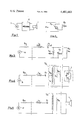
- FIG. 1 is a block diagram showing the connection of the invention between a loudspeaker driver and a source of audio frequency electrical energy
- FIG. 2 shows the equivalent circuit for the transducer
- FIG. 3 is a schematic diagram of a two-pole Butterworth filter
- FIG. 4 is a schematic diagram of an example of the invention connected between a transducer and a generator;
- FIG. 5 also is a schematic diagram of an example of the invention connected between a transducer and a generator.
- FIG. 1 contains the schematic diagram of an equivalent circuit for a typical piezoceramic transducer, such as transducer 1 depicted in FIG. 1.
- the input impedance to piezoceramic transducer 1 can be represented by the parallel combination of the transducer capacitor 2 and the transducer resistor 3 shown in FIG. 2.
- a typical value for the transducer capacitor 2 is 0.3 microfarads and a typical value for the transducer resistor 3 is 175 ohms.
- This invention is based on an adaptation of a bandpass network, such as a constant K or M-derived type of bandpass network, or a "modern" bandpass network such as a Butterworth, Tschebyscheff or flat time delay (Bessel polynomials) type of network, all of which are well-known in the art.
- the invention is based on any of the filters of this general type having two or more "poles" that have an output stage consisting of a parallel combination of an inductor and a capacitor.
- the inductor and capacitor in the output stage of the filter, together with the load resistor into which the filter is designed to operate, are replaced in this invention by an autotransformer which is connected to the piezoceramic transducer.
- a shunting resistor is also connected across the transducer.
- FIG. 3 contains an example of a two-pole Butterworth bandpass filter which is designed to operate with an 8-ohm load resistor and a voltage generator having zero internal impedance.
- the bandpass filter in this example has a high frequency cutoff, or -3 db point, at 20 kHz, and a low frequency cutoff at 5 kHz.
- inductor L8 and capacitor C9 in the output stage of the filter and the load resistor R10 are replaced by an autotransformer that is connected to piezoceramic transducer 1 to which also may be added a shunt resistor across the transducer.
- autotransformer T13 consists of a number of turns of wire, wound on a magnetic core, which core may be in the shape of a toroid, a pot-core, an E-core, or other suitable shape, such that nearly all of the magnetic flux generated by the winding passes through all of the turns of the autotransformer, thus providing a low or negligible short circuit reactance for the autotransformer.
- the autotransformer is connected as shown in FIG. 4, with intermediate tap TP15 connected to capacitor C7.
- the autotransformer is selected such that the input impedance between the ground or common connection of the autotransformer and the input at tap TP15 is equal to the value of inductor L8 (0.267 millihenrys) when the output of the autotransformer is open circuited.
- the turns ratio of the number of windings in the input and output of the autotransformer is selected so as to transform the value of transducer capacitor C2 (0.3 ⁇ Fd) at the input tap of autotransformer T13, to a value equal to capacitor C9, that is to 0.938 microfarads.
- the ratio of N2/N1 is given by ##EQU1## or ##EQU2##
- resistor R14 in parallel with resistor R3 must be equal to an amount given by ##EQU3##
- the value of the shunt resistor, R14, accordingly is given by ##EQU4##
- the requirement that the open circuit inductance at the input of autotransformer T13 be 0.267 millihenrys can also be considered to be the requirement that the open circuit inductance of the autotransformer be 0.835 millihenrys when viewed at the output terminals.
- the input impedance to the autotransformer when connected to transducer 1, can be made to appear the same as the parallel combination of capacitor C9 and inductor L8 in the output stage of the filter and the load resistor R10.
- a shunt resistor will not be necessary if the load resistance for which the filter is designed, is approximately equal to the effective value of the transducer resistance after transformation by the autotransformer.
- the preferred embodiment for the example of this invention given above, is the series combination of inductor L6 and capacitor C7 connected to autotransformer T13 having a turns ratio N2/N1 of 1.77 and an open circuit reactance as viewed from the output of autotransformer T13 of 0.84 millihenry, the output of which transformer is connected to piezoceramic transducer 1 and to shunt resistor R14 having a resistance of 29 ohms.
- Autotransformer T13 could be replaced by a two-winding transformer having a small short circuit input inductance and having an open circuit input inductance equivalent to an inductance of 0.267 millihenrys. It also should be apparent that the division of the power delivered to shunt resistor R14 and to transducer 1 can be altered by adding a shunt capacitance across transducer 1 and adjusting the other circuit parameters accordingly.
- the autotransformer could also be described or characterized as an "auto inductor" since it is designed not only to transform impedances connected at its output, but also to exhibit a specified inductance at its input when the output is open circuited.
- the magnetic-core of the autotransformer in the preferred embodiment will contain an air-gap.
- the network of this invention is not limited to a network based on the two-pole Butterworth bandpass network shown in the example.
- Networks with a higher number of "poles”, e.g. 3, 4, 5 or 6 or more poles, can be used as the basis for this invention, the only requirement being that the output stage of the filter consist of the parallel combination of an inductor and a capacitor, which capacitor and inductor together with the load resistor for the filter can be replaced by an autotransformer and a shunt resistor connected to the piezoceramic transducer.
- the input stage of the filter upon which the network of this invention is based, should consist of a series combination of an inductor and a capacitor, such as that shown in FIG. 3. If the generator is a current source, then the input stage of the network should be a parallel combination of an inductor and a capacitor. For a generator which has a finite internal resistance, a filter with either a series or parallel input may be used as the basis for the network of this invention.
- the network of this invention operates as a bandpass filter to transfer electrical energy to the transducer over a desired range of frequencies. It also operates to cause the transducer to operate in a relatively uniform manner over the pass band.
- the network further operates to transform the equivalent input resistance of the transducer to a lower value to match the design impedance of the amplifier so that a greater amount of electrical energy from the generator or amplifier will be transferred to the transducer over the range of frequencies within the passband of the filter.
Abstract
Description
Claims (13)
Priority Applications (1)
| Application Number | Priority Date | Filing Date | Title |
|---|---|---|---|
| US06/494,137 US4481663A (en) | 1980-10-10 | 1983-05-16 | Network for use with piezoceramic transducer |
Applications Claiming Priority (2)
| Application Number | Priority Date | Filing Date | Title |
|---|---|---|---|
| US19603780A | 1980-10-10 | 1980-10-10 | |
| US06/494,137 US4481663A (en) | 1980-10-10 | 1983-05-16 | Network for use with piezoceramic transducer |
Related Parent Applications (1)
| Application Number | Title | Priority Date | Filing Date |
|---|---|---|---|
| US19603780A Continuation | 1980-10-10 | 1980-10-10 |
Publications (1)
| Publication Number | Publication Date |
|---|---|
| US4481663A true US4481663A (en) | 1984-11-06 |
Family
ID=26891606
Family Applications (1)
| Application Number | Title | Priority Date | Filing Date |
|---|---|---|---|
| US06/494,137 Expired - Fee Related US4481663A (en) | 1980-10-10 | 1983-05-16 | Network for use with piezoceramic transducer |
Country Status (1)
| Country | Link |
|---|---|
| US (1) | US4481663A (en) |
Cited By (11)
| Publication number | Priority date | Publication date | Assignee | Title |
|---|---|---|---|---|
| US4653101A (en) * | 1984-03-27 | 1987-03-24 | William Beith | Audio reverberator |
| US4955059A (en) * | 1989-03-29 | 1990-09-04 | Motorola, Inc. | Speaker power matching method and apparatus |
| WO1996001547A2 (en) * | 1994-07-06 | 1996-01-18 | Noise Cancellation Technologies, Inc. | Piezo speaker and installation method for laptop personal computer and other multimedia applications |
| US6125188A (en) * | 1997-10-18 | 2000-09-26 | Matthew C Hennessy | Compact personal monitor system |
| US20030048915A1 (en) * | 2000-01-27 | 2003-03-13 | New Transducers Limited | Communication device using bone conduction |
| US20030059068A1 (en) * | 2000-01-27 | 2003-03-27 | New Transducers Limited | Electronic article comprising loudspeaker and touch pad |
| US20030059069A1 (en) * | 2000-01-27 | 2003-03-27 | New Transducers Limited | Loudspeaker |
| US6865277B2 (en) | 2000-01-27 | 2005-03-08 | New Transducers Limited | Passenger vehicle |
| US7149318B2 (en) | 2000-01-24 | 2006-12-12 | New Transducers Limited | Resonant element transducer |
| US20160277833A1 (en) * | 2013-09-18 | 2016-09-22 | Zte Corporation | Piezoelectric Speaker Driving Device |
| US20220128617A1 (en) * | 2020-10-22 | 2022-04-28 | Yokogawa Electric Corporation | Diagnostic device, diagnostic method, and field device |
Citations (4)
| Publication number | Priority date | Publication date | Assignee | Title |
|---|---|---|---|---|
| US1907723A (en) * | 1929-09-28 | 1933-05-09 | Bell Telephone Labor Inc | Sound reproducing device |
| GB564460A (en) * | 1943-06-11 | 1944-09-28 | Fred Pyrah | Improvements in or relating to attenuation compensators |
| US3262075A (en) * | 1961-11-07 | 1966-07-19 | Anzac Electronics Inc | Impedance matching transformer |
| US4237340A (en) * | 1977-06-02 | 1980-12-02 | Klipsch And Associates, Inc. | Crossover network for optimizing efficiency and improving response of loudspeaker system |
-
1983
- 1983-05-16 US US06/494,137 patent/US4481663A/en not_active Expired - Fee Related
Patent Citations (4)
| Publication number | Priority date | Publication date | Assignee | Title |
|---|---|---|---|---|
| US1907723A (en) * | 1929-09-28 | 1933-05-09 | Bell Telephone Labor Inc | Sound reproducing device |
| GB564460A (en) * | 1943-06-11 | 1944-09-28 | Fred Pyrah | Improvements in or relating to attenuation compensators |
| US3262075A (en) * | 1961-11-07 | 1966-07-19 | Anzac Electronics Inc | Impedance matching transformer |
| US4237340A (en) * | 1977-06-02 | 1980-12-02 | Klipsch And Associates, Inc. | Crossover network for optimizing efficiency and improving response of loudspeaker system |
Non-Patent Citations (1)
| Title |
|---|
| H. Tremaine, Audio Cyclopeda, Mar. 1977, Howard W. Sams & Co., Inc., pp. 353 and 368. * |
Cited By (19)
| Publication number | Priority date | Publication date | Assignee | Title |
|---|---|---|---|---|
| US4653101A (en) * | 1984-03-27 | 1987-03-24 | William Beith | Audio reverberator |
| US4955059A (en) * | 1989-03-29 | 1990-09-04 | Motorola, Inc. | Speaker power matching method and apparatus |
| WO1990011669A1 (en) * | 1989-03-29 | 1990-10-04 | Motorola, Inc. | Speaker power matching method and apparatus |
| WO1996001547A2 (en) * | 1994-07-06 | 1996-01-18 | Noise Cancellation Technologies, Inc. | Piezo speaker and installation method for laptop personal computer and other multimedia applications |
| WO1996001547A3 (en) * | 1994-07-06 | 1996-02-22 | Noise Cancellation Tech | Piezo speaker and installation method for laptop personal computer and other multimedia applications |
| US5638456A (en) * | 1994-07-06 | 1997-06-10 | Noise Cancellation Technologies, Inc. | Piezo speaker and installation method for laptop personal computer and other multimedia applications |
| US6125188A (en) * | 1997-10-18 | 2000-09-26 | Matthew C Hennessy | Compact personal monitor system |
| US7149318B2 (en) | 2000-01-24 | 2006-12-12 | New Transducers Limited | Resonant element transducer |
| US7684576B2 (en) | 2000-01-24 | 2010-03-23 | New Transducers Limited | Resonant element transducer |
| US20070086616A1 (en) * | 2000-01-24 | 2007-04-19 | New Transducers Limited | Resonant element transducer |
| US20030059068A1 (en) * | 2000-01-27 | 2003-03-27 | New Transducers Limited | Electronic article comprising loudspeaker and touch pad |
| US6885753B2 (en) | 2000-01-27 | 2005-04-26 | New Transducers Limited | Communication device using bone conduction |
| US6965678B2 (en) | 2000-01-27 | 2005-11-15 | New Transducers Limited | Electronic article comprising loudspeaker and touch pad |
| US6865277B2 (en) | 2000-01-27 | 2005-03-08 | New Transducers Limited | Passenger vehicle |
| US7151837B2 (en) | 2000-01-27 | 2006-12-19 | New Transducers Limited | Loudspeaker |
| US20030059069A1 (en) * | 2000-01-27 | 2003-03-27 | New Transducers Limited | Loudspeaker |
| US20030048915A1 (en) * | 2000-01-27 | 2003-03-13 | New Transducers Limited | Communication device using bone conduction |
| US20160277833A1 (en) * | 2013-09-18 | 2016-09-22 | Zte Corporation | Piezoelectric Speaker Driving Device |
| US20220128617A1 (en) * | 2020-10-22 | 2022-04-28 | Yokogawa Electric Corporation | Diagnostic device, diagnostic method, and field device |
Similar Documents
| Publication | Publication Date | Title |
|---|---|---|
| US3671885A (en) | High frequency signal routing devices for use in catv systems | |
| US5260862A (en) | A-C power line filter | |
| US4481663A (en) | Network for use with piezoceramic transducer | |
| US5227962A (en) | Filter and power factor compensation network | |
| US4323736A (en) | Step-up circuit for driving full-range-element electrostatic loudspeakers | |
| US5598480A (en) | Multiple output transformer network for sound reproducing system | |
| US4878244A (en) | Electronic hybrid circuit | |
| US3931469A (en) | Crossover network for a multi-element electrostatic loudspeaker system | |
| US3838215A (en) | Speakers and crossover circuit | |
| US5327505A (en) | Multiple output transformers network for sound reproducing system | |
| US4028505A (en) | Negative impedance repeater for telephone lines | |
| JP2004519941A (en) | Circuit and method for input impedance matching of a power amplifier in an electronic device | |
| US4039977A (en) | Adjustable compensating circuit having differential capacitor in each tunable stage | |
| US4032866A (en) | Low loss frequency response corrective network | |
| US3952256A (en) | Multi-impedance output for transistor power amplifier | |
| WO1980002484A1 (en) | Feedback arrangement | |
| US5956410A (en) | Audio transmission line with energy storage network | |
| US5121088A (en) | Frequency response equalizer | |
| JP3373659B2 (en) | Passband control method of coupling filter for distribution line carrier communication | |
| JPS6214734Y2 (en) | ||
| US3474355A (en) | Circuit for decreasing characteristic losses of inductors | |
| US2607860A (en) | Frequency selective repeater device | |
| US4085299A (en) | Peak amplitude protection system for ribbon loudspeakers | |
| JPS6143298Y2 (en) | ||
| US3559091A (en) | Broadband interstage coupling circuit |
Legal Events
| Date | Code | Title | Description |
|---|---|---|---|
| AS | Assignment |
Owner name: ALTEC LANSING CORPORATION, 101 COLLEGE ROAD, EAST, Free format text: ASSIGNMENT OF ASSIGNORS INTEREST.;ASSIGNOR:ALTEC CORPORATION;REEL/FRAME:004441/0472 Effective date: 19850715 |
|
| AS | Assignment |
Owner name: MARINE MIDLAND BANK, N.A., ONE MARINE MIDLAND CENT Free format text: SECURITY INTEREST;ASSIGNOR:ALTEC LANSING CORPORATION;REEL/FRAME:004761/0630 Effective date: 19870416 Owner name: MARINE MIDLAND BANK, N.A.,NEW YORK Free format text: SECURITY INTEREST;ASSIGNOR:ALTEC LANSING CORPORATION;REEL/FRAME:004761/0630 Effective date: 19870416 |
|
| REMI | Maintenance fee reminder mailed | ||
| AS | Assignment |
Owner name: ALTEC LANSING CORPORATION Free format text: RELEASED BY SECURED PARTY;ASSIGNOR:MARINE MIDLAND BANK, N.A., AS AGENT;REEL/FRAME:005041/0028 Effective date: 19880223 |
|
| LAPS | Lapse for failure to pay maintenance fees | ||
| STCH | Information on status: patent discontinuation |
Free format text: PATENT EXPIRED DUE TO NONPAYMENT OF MAINTENANCE FEES UNDER 37 CFR 1.362 |
|
| FP | Lapsed due to failure to pay maintenance fee |
Effective date: 19881106 |
|
| FEPP | Fee payment procedure |
Free format text: PAYOR NUMBER ASSIGNED (ORIGINAL EVENT CODE: ASPN); ENTITY STATUS OF PATENT OWNER: LARGE ENTITY |