US3797787A - Jet engine blast fence - Google Patents
Jet engine blast fence Download PDFInfo
- Publication number
- US3797787A US3797787A US00244097A US3797787DA US3797787A US 3797787 A US3797787 A US 3797787A US 00244097 A US00244097 A US 00244097A US 3797787D A US3797787D A US 3797787DA US 3797787 A US3797787 A US 3797787A
- Authority
- US
- United States
- Prior art keywords
- blast
- shield plate
- fence
- expanded metal
- retaining frame
- Prior art date
- Legal status (The legal status is an assumption and is not a legal conclusion. Google has not performed a legal analysis and makes no representation as to the accuracy of the status listed.)
- Expired - Lifetime
Links
Images


Classifications
-
- B—PERFORMING OPERATIONS; TRANSPORTING
- B64—AIRCRAFT; AVIATION; COSMONAUTICS
- B64F—GROUND OR AIRCRAFT-CARRIER-DECK INSTALLATIONS SPECIALLY ADAPTED FOR USE IN CONNECTION WITH AIRCRAFT; DESIGNING, MANUFACTURING, ASSEMBLING, CLEANING, MAINTAINING OR REPAIRING AIRCRAFT, NOT OTHERWISE PROVIDED FOR; HANDLING, TRANSPORTING, TESTING OR INSPECTING AIRCRAFT COMPONENTS, NOT OTHERWISE PROVIDED FOR
- B64F1/00—Ground or aircraft-carrier-deck installations
- B64F1/26—Ground or aircraft-carrier-deck installations for reducing engine or jet noise; Protecting airports from jet erosion
Definitions
- a jet engine blast fence comprising a blast shield plate made of an expanded metal, a retaining frame to which said blast shield plate is affixed and a base for fixing the retaining frame to the ground in such a manner that the retaining frame is inclined toward the jet blast, the said expanded metal having strands sloping upward in the lee direction, the said strands defining openings which are also horizontally clear so that a.
- part of the blast is positively allowed to pass horizontally through said openings of the expanded metal and is raised upward by a part of the blast which part is deflected obliquely upward in the lee direction along the strands of the expanded metal.
- This invention relates generally to a jet engine blast fence and more particularly to a blast fence to be disposed on the ground behind large jet engines on an aircraft or the like to deflect upwardly most of the hot and high velocity exhaust streams from the jet engines.
- Such blast gases have created a serious aircraft knowrT as the Douglas DC7C has a blast velocity of about meters per second at 60 feet behind the engines.
- the turbojet airplanes known as the Boeing 707E1 6 Boeing 747 have engines which produce ex tremely powerful hot blasts having velocities of 106 m/sec. and 150 to I70 m/sec., respectively,at the same distance aft of the engines. in the vicinity of the nozzle of such turboject engines, the blast has a temperature above 300C and the blast pressure exceeds 1,000 kg/m".
- the jet blast pulsates.
- the blast must be handled or controlled in anentirely different manner from that for natural wind of 50 to 60 m/sec. or the blast behind a propeller-driven aircraft.
- Such conventional structures include blast fences each constructed of an adequate'frame member and a plate attached thereto, the plate being a concrete plate, a corrugated steel plate, a slit metal plate or the like. Nevertheless, the blast fences incorporating the first and second types of plate are dangerous because of not providing any forward visibility therethrough and the fences must be so rigid as to withstand the blast pressure exerted all over, which'gives them a heavy appearance. In addition to these and other drawbacks, there is a defect that a negative pressure and turbulence are produced behind any such blast fence which pulls up a cloud of dust.
- the blast fence including the third or slit metal plate is not capable of effective shielding of the of the aforesaid turbojetengine.
- a jet engine blast fence characterized by comprising a blast shield plate made of an expanded metal, a retaining frame to which said blast shield plate is affixed and a base for fixing the retaining frame to the ground in such a manner that the retaining frame is inclined toward the jet blast, the said expanded metal having strands sloping upward in the lee direction, the said strands defining openings which are also horizontally clear so that a part of the blast is positively allowed to pass horizontally through said openings of the expanded metal and is raised upward by a part of the blast which part is deflected obliquely upward in the lee direction along the strands of the expanded metal.
- An object of the present invention is to provide a blast fence which is sufficiently resistant to the pressure of the blast issuing from a large jet engine and has an excellent shielding effect on the jet blast to such an extent that, behind the blast fence disposed aft of the jet engine, vehicles can travel safely and workers can perform their duties in safety and without any decrease in working efficiency.
- Another object of the invention is to provide a blast fence having the above described blast shielding effect and also capable of providing forward visibility through the blast fence so that it is possible to inspect the operating and other conditions of the jet engine.
- Still another object of the invention is to provide a blast fence including a blast shield plate which can be of extremely light construction without losing the necessary strength, so that the fabrication cost of the fence can be markedly lowered.
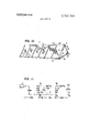
- FIG. 1 is a perspective view of a portion of a blast fence embodying the present invention, as viewed from the lee side.
- FIG. 2 is a side view of the blast fence shown in FIG. 1.
- FIG. 3 is a front view of a part of the blast fence illustrated in FIG. 2.
- FIG. 4 is an enlarged cross-sectional view taken along the line lVlV of FIG. 1, showing the principal construction of a retaining frame.
- FIG. 5 is an enlarged cross-sectional view taken along the line V-V of FIG. 1 showing the construction of'a part of the retaining frame.
- FIG. 6 is a front view corresponding to FIG. 5.
- FIG. 7 is an enlarged perspective view of a strut shoe of the blast fence.
- FIG. 8 is an enlarged fragmentary perspective view showing in detail the construction of a blast shield plate for use in the blast fence of the present invention.
- FIG. 9 is an enlarged cross-sectional view taken along the line IXIX of FIG. 8.
- FIG. 10 is a perspective view of another blast fence embodying the invention.
- FIG. 11 is a graph showing an exemplary shielding effect of a blast fence according to the invention.
- a blast fence F made in accordance with the present invention comprises, as main components, a retaining frame 1, struts 11 and a shield plate 21 affixed to the retaining frame 1.
- the retaining frame 1 includes an upper horizontal member 2, a lower horizontal member 3 and a middle one 4, each being made of I-I-section steel beams. These three members extending horizontally are equally spaced apart stepwise.
- the upper horizontal member 2 is connected to the middle horizontal member 4 by a plurality of upper longitudinal members 5 made of H-section steel beams which are laterally spaced at regular intervals.
- the middle horizontal member 4 is coupled to the lower horizontal member 3 by lower longitudinal members 6.
- the retaining frame 1 has a plurality of laterally disposed pairs of upper and lower sub-frames.
- the upper horizontal member 2 is secured to the upper longitudinal members 5 in such a manner that the flanges 2a of the H-section steel beam of the upper horizontal member 2 are made to abut the flanges 5a of the upper longitudinal members 5, the flanges 2a and 5a being welded together at the abutments.
- the middle horizontal member 4 is positioned with the web 4a of the H-section steel beam extending substantially horizontally.
- the upper and lower edges of the flange 4b are made to abut against and are welded to the flanges 5a of the upper longitudinal members 5 and the flanges 6a of the lower longitudinal members 6, respectively.
- the lower longitudinal members 6 thus fastened to the middle horizontal member 4 are in slightly bent relationship to the upper longitudinal members 5 with the middle horizontal member 4 therebetween.
- the lower horizontal member 3 is firmly connected to the lower longitudinal members 6 by making the flanges 3a of the H-section steel beam of the lower horizontal member 3 abut the flanges 6a of the lower longitudinal members 6 and welding the flanges 3a and 6a at the abutments.
- each intermediate member 10 is an L-section steel beam, the webs 10a of which are integrally attached face to face, with the flanges facing outward, or rearward.
- the upper and lower ends of one of the alighed intermediate members 10 are welded to the upper and middle horizontal members 2 and 4 re spectively, while the upper and lower ends of the other are welded to the middle and lower horizontal members 4 and 3 respectively.
- the intermediate members 10 not only stiffen the retaining frame 1 but also allow the shield plate 21 to be securely attached to the retaining frame so as not to bulge leeward under the pressure of the jet blast.
- Brackets 7, 8 and 9 are welded to the front surface (the surface on the right side in FIGS. 2 and 4) of the retaining frame 1 thus formed, at an upper portion of each upper longitudinal member 5 and an upper and a lower portion of each lower longitudinal member 6, respectively.
- Struts l2, l3 and 14 made of L-section steel beam are secured to the brackets 7, 8 and 9 respectively by means of bolts 15.
- the struts 12 and 13 slope downwardly and forwardly, while the strut 14 extends horizontally.
- the leading ends of the struts 12, 13 and 14 bracketed to each pair of longitudinal members 5 and 6 are connected to a strut shoe 16 by bolts 17 at a place where the said ends come together.
- the horizontally extending strut 14 is fixed to the bracket 9 so as to make an angle [3 of about 50 to with the lower longitudinal member 6.
- the blast shield plate 21 is made of a marketed expanded metal 24, which is produced by forming zigzag slits in a thin or medium-thickness plate by means of a recticulating cutter and expanding the slit plate into a meshwork.
- the expanded metal 24, produced by stretching the raw plate, has strands 25 inclined in relation to an enveloping plane E of the expanded metal 24, and the angle of the inclination is now referred to as the opening angle 7." (Refer to FIG. 9.) Also, when the expanded metal 24 is projected on a plane parallel to the expanded metal plane E, the ratio of the area of the rhombic mesh or opening 26 enclosed by the strands 25 to the whole area of the expanded metal 24 is called the "the clearance ratio.”
- the opening angle is determined by the thickness 1, feed width W and clearance ratio of the expanded metal 24 and other factors.
- the blast shield plate 21 thus formed is affixed to the retaining frame 1 in the following manner: Previously the expanded metal is cut into rectangular sections matched to the full size of the sub-frames formed by the component members of the retaining frame 1. The rectangular sections of the expanded metal 24 are pressed to the inside surfaces (facing forward) of the rear flanges'2a, 3a, 4b, 5a, 6a, and 10b of the said members, and welded to the flanges along the circumferential sides of the rectangular sections of the expanded metal 24. In the blast shield plate 21 affixed to the retaining frame 1, the openings 26 of the expanded metal 24 face slantingly upwardly in the lee direction. The blast shield plates 21 are divided into an upper portion 22 and a lower portion 23 by the aforesaid middle horizontal member 4.
- the blast fence F fabricated as described above is secured to the ground G as shown in FIGS. 1 and 2.
- the brackets 9 of the retaining frame 1 have base plates 9a through which anchor bolt holes 9b are provided.
- Anchor bolts 190 are embedded at their lower portions in the foundation blocks 19 and passed through the bolt holes 9b to fasten the rear part of the blast fence F to the ground.
- anchor bolts 18a partly embedded in the foundation blocks 18 are passed through anchor bolt holes 16b in the base plates 16a of the strut shoes 16, thereby securing the front part of the blast fence F to the ground G.
- the angle [3 between the lower longitudinal member 6 and a horizontal plane is approximately 50 to 55, so that the blast fence F fastened to the ground has a forward inclination, that is, an inclination toward the jet engine exhaust blast.
- the height of the blast fence F as anchored depends on the size and mounting level of the jet engines and the height of the objects to be protected, and a normally preferable fence height for a large jet liner is 3.5 to 4.5 meters.
- the width of the blast fence F depends on the size and arrangement of the Jet engines. For large jet liners, the overall transverse width of each type of airplane parked with its longitudinal axis perpendicular to the blast fence F is considered to be the minimum fence width.
- the members of the retaining frame 1 are formed of H- section steel beams and L-section steel beams. It is nevertheless clear that the said members are not limited to these shapes but may be made of other types of shaped steel. The strength of these members is determined in accordance with the height of the blast fence F and the energy of the jet blast. Besides, the use of H- and L- section steel beams as in the present embodiment to construct the retaining frame 1 makes the whole blast fence F a light structure and also facilitates secure attachment of the blast shield plate 21 to the retaining frame 1.
- the present invention has taken into consideration the fact that jet gases are high in temperature.
- the blast fence F is inclined toward the blast with a high clearance ratio so that the horizontal blast A from the jet engines is positively passed rearwardly, and the cooperative effect of the upward flow of the jet gases B and C deflected upwardly upon impingement against the strands 25 of the expanded metal 24 of the blast shield plate 21.
- the tendency of these gases to rise due to high temperature of the blast gases D flowing over the blast fence F, and the phenomenon of ascent of the passed gases themselves, causes most of the blast gases blowing up the blast fence F to rise up immediately behind the blast fence F.
- the retaining frame has a bend between the upper and lower portions thereof, substantially at the height of its middle.
- the upper blast shield plate 22 slopes upwardly toward the blast at an angle of approximately 10 to 15 with respect to a vertical plane (the angle a in FIG. 2), while the lower blast shield plate 23 is likewise inclined at an angle of approximately 35 to 40 (the angle B in FIG. 2).
- the blast fence F inclined as in the present invention provides a broad working area in front of the blast fence F, with a resultant higher working effeciency.
- the present invention Since the present invention has the lower blast shield plate 23 inclined at an angle [3 of approximately 35 to 40, the blast gases C are turned through a large turning angle, thus raising the blast gases B redirected at the upper blast shield plate 22, so that the weak wind region behind the blast fence F has a maximum area.
- the above described matters have also been taken into account in deciding that the inclination angle a of the upper blast shield plate 22 to be about 10 should 15.
- the essential structural factors of the expanded metal 24 constituting the blast shield plate 22 have limits for the following reasons:
- the present inventor investigated the maximum tolerable wind belocity in the weak wind zone at the rear of the blast fence and contemplated allowing positive passage of blast gases rearwardly of the blast fence within the ascertained limit.
- the thickness r and clearance ratio of the expanded metal 24 have significant influence upon the intended effect, and after having conducted various experiments and studies, it has been found that the plate thickness 2 and the clearance ratio should be 4.0 to 7.0 mm and about 60 to 80 percent respectively.
- the expanded metal 24 can not withstand the pulsating blast and may become fatigued and rupture at the welds thereof, Meanwhile, if the thickness exceeds mm, the expanded metal 24 receives such a high pressure that the blast fence F is in danger of tipping.
- the clearance ratio is less than 60 percent, a smaller part of the blast can pass rearwardly through the blast fence F. As a result, the pressure exerted on the blast fence F is increased while the visibility therethrough is decreased, and also dust may rise up at the rear of the blast fence F. On the other hand, if the clearance ratio is higher than percent, too much jet gases flow through the blast fence F, which therefore can not play its role.
- the opening angle y of the expanded metal 24 is determined in accordance with the thickness 1, the feed width W and the clearance ratio.
- the thickness I and the clearance ratio are within the aforesaid ranges, that is, 4.0 to 7.0 mm and 60 to 80 percent respectively, the opening angle 7 is approximately 20 to 45.
- the inclination angle of the strands 25 of the expanded metal 24 in relation to a horizontal plane H or the ground G can be expressed as follows:
- the inclination angle 6 of the strands 25 of the expanded metal 24 is practically 30 to 60 in the upper shield plate 22 and 55 to 85 in the lower shield plate 23.
- the inclination angle 6 is the angle at which the jet gases are in practice diverted upward.
- the inclination angle a and B of the retaining frame 1 are determined so that the inclination angle 9 of the strands 25 of the expanded metal 24 in regard to the ground G comes within the said ranges.
- the openings 26 of the expanded metal thus obliquely positioned are also horizontally clear.
- the clearance ratio. with respect to the vertical plane. of the expanded metal 24 inclined in relation to the ground as stated above is as high as approximately to 60 percent so that a part of the blast passes through the expanded metal 24 in the horizontal direction.
- the blast portion which has passed horizontally is lifted up by a portion of the blast which has been redirected slantingly upwardly in the lee direction along the strands of the expanded metal 24.
- the jet gases B and C deflected upwardly by the strands 25 of the expanded metal 24 of the blast shield plate 21 and the jet gases D flowing over the blast fence F serve to raise most of the gases which have passed horizontally through the shield plate 21.
- the blast velocity is 100 m/sec..
- the wind velocity at a point 5 meters behind the blast fence F and 3 meters above the ground is below 15 m/sec., that is, below the maximum velocity which allows maintenance and other work on aircraft.
- the jet gas temperature at the point 5 meters behind the blast fence F and 3 meters above the ground falls below 22C. even when the exhaust temperature in the vicinity of the engine nozzle is 50C. thus posing no problem.
- the clearance ratio is high. the pressure exerted on the blast fence F is so low that the blast fence F stands in safety and with sufficient visibility.
- FIG. 11 shows an example of the blast shielding effect of the blast fence F of the present invention, and more particularly illustrates the blast velocity distribution at various distances from the jet engine nozzle J when the blast fence F is at a point 15 meters behind the said nozzle.
- a chart 31 shows the distribution of blast velocity values (m/sec) at vertical intervals of one meter from the ground to a height of 4 meters at a position 12 meters behind the jet engine nozzle J and 3 meters ahead of the blast fence F. and charts 32 and 33 indicate the blast velocity distribution at positions 5 meters and l 1 meters behind the blast fence F. respectively.
- the upper section 22 of the blast fence F can be omitted, with the lower section 23 left as a one-step blast fence F.
- This blast fence F although a one step fence, exhibits the same blast shielding effect as the two-step blast fence F.
- the blast fence of the present invention can active a suffrcient shielding effect against high velocity jet gases exhausted from large jet engines, and ensures structural safety.
- a jet engine blast fence comprising:
- a retaining frame to which the blast shield plate is afa base on which said retaining frame is mounted for fixing the retaining frame to the ground with the retaining frame inclined toward the jet blast.
- a blast shield plate made of an expanded metal having a plate thickness of 4.0 to 7.0 mm and a clearance ratio relative to an enveloping plane of the expanded metal of approximately 60 to percent.
- said expanded metal having the strands thereof sloping upwardly in the lee direction, the said strands defining openings which are also clear in the horizontal direction,
- a blast fence as defined in claim 1 wherein said retaining frame comprises:
- an upper and a lower horizontal member both being of shaped steel and substantially equally spaced upwardly and downwardly from said middle horizontal member
- said horizontal and longitudinal members together constituting a compassion structure wherein a plurality of upper and lower sub-frames are formed.
- a blast fence as claimed in claim 2 wherein said members of said frame have flanges thereon and said blast shield plate is secured to said retaining frame all over said retaining frame, the said blast shield plate consisting of plate sections the circumferential sides of which are welded to the flanges of the said horizontal and longitudinal members.
- a blast fence as claimed in claim 2 wherein said blast shield plate is comprised of separate upper and lower sections which are bent in respect to each other with the middle horizontal member disposed therebetween and the angle of inclination of the upper blast shield plate in relation to a vertical plane is slightly smaller than that of the lower shield plate,
Abstract
A jet engine blast fence comprising a blast shield plate made of an expanded metal, a retaining frame to which said blast shield plate is affixed and a base for fixing the retaining frame to the ground in such a manner that the retaining frame is inclined toward the jet blast, the said expanded metal having strands sloping upward in the lee direction, the said strands defining openings which are also horizontally clear so that a part of the blast is positively allowed to pass horizontally through said openings of the expanded metal and is raised upward by a part of the blast which part is deflected obliquely upward in the lee direction along the strands of the expanded metal.
Description
United States Patent [191 Watanabe, deceased 1 Mar. 19, 1974 JET ENGINE BLAST FENCE "invader; filiosulie watanabeideceisetf, n55? Tokyo, Japan Naoko Watanabe, sole successor Assignee: Nippon Steel Corporation,
Tokyo, Japan Filed? Apr. 14,1972
Appl. No.: 244,097
Foreign Application Priority Data Apr. 17, 1971 Japan 46-29783 US. Cl. 244/114 B, 256/24 Int. Cl E04h 17/16 Field of Search 256/24, 25, 26, 12.5, 73,
References Cited UNITED STATES PATENTS 6/1965 David 244/114 B 11/1961 Phillips et al,.... 244/114 B 5/1916 Swezey 256/l2.5 l/l925 Naud 256/l2l5 l/l940 Briggs 256/l2.5 UX
2,765,994 10/1956 Jordanoff.... 256/l2.5 X 3,037,726 6/1962 Phillips 244/114 B FOREIGN PATENTS OR APPLICATIONS l65,859 l/l959 Sweden 256/12.5
Primary Examiner-Dennis L. Taylor Attorney, Agent, or FirmWenderoth, Lind & Ponack [5 7 ABSTRACT A jet engine blast fence comprising a blast shield plate made of an expanded metal, a retaining frame to which said blast shield plate is affixed and a base for fixing the retaining frame to the ground in such a manner that the retaining frame is inclined toward the jet blast, the said expanded metal having strands sloping upward in the lee direction, the said strands defining openings which are also horizontally clear so that a.
part of the blast is positively allowed to pass horizontally through said openings of the expanded metal and is raised upward by a part of the blast which part is deflected obliquely upward in the lee direction along the strands of the expanded metal.
5 Claims, 11 Drawing Figures PAIENIEnm 1 9 1914 saw 1 or 3 FIG. 3
PATENTEBHAR 19 m4 3 78 7 mil 3 BF 3 JET ENGINE BLAST FENCE BACKGROUND OF THE INVENTION 1. Field of the Invention This invention relates generally to a jet engine blast fence and more particularly to a blast fence to be disposed on the ground behind large jet engines on an aircraft or the like to deflect upwardly most of the hot and high velocity exhaust streams from the jet engines.
2. Description of the Prior Art A recent trend has been toward competition for larger pay loads on airplanes and higher speeds thereof, resulting of necessity in requiring the engines mounted on aircraft to develop greater power outputs. With the advent of powerful jet engines, much attention has been attracted by hazardous rearward jet blasts which never posed any serious problem in the era of propeller-driven airplanes of small and medium sizes.
This tendency is particularly pronounced with the current development of jet engines for use in aircraft, some of which are turbojet airplanes designed to be propelled directly by rapid jets produced by acceleration of high temperature, high velocity combustion gases through several stages of turbines. The engines of such turbojet planes generate jet blasts of considerably 5 jet blasts.
ing take-off. Such blast gases have created a serious aircraft knowrT as the Douglas DC7C has a blast velocity of about meters per second at 60 feet behind the engines. the turbojet airplanes known as the Boeing 707E1 6 Boeing 747 have engines which produce ex tremely powerful hot blasts having velocities of 106 m/sec. and 150 to I70 m/sec., respectively,at the same distance aft of the engines. in the vicinity of the nozzle of such turboject engines, the blast has a temperature above 300C and the blast pressure exceeds 1,000 kg/m". Moreover, the jet blast pulsates. Thus, the blast must be handled or controlled in anentirely different manner from that for natural wind of 50 to 60 m/sec. or the blast behind a propeller-driven aircraft.
In order to obviate the above-mentioned problem, various blast shielding structures have so far been devised. However, these are not suitable for practical use.
Such conventional structures include blast fences each constructed of an adequate'frame member and a plate attached thereto, the plate being a concrete plate, a corrugated steel plate, a slit metal plate or the like. Nevertheless, the blast fences incorporating the first and second types of plate are dangerous because of not providing any forward visibility therethrough and the fences must be so rigid as to withstand the blast pressure exerted all over, which'gives them a heavy appearance. In addition to these and other drawbacks, there is a defect that a negative pressure and turbulence are produced behind any such blast fence which pulls up a cloud of dust. The blast fence including the third or slit metal plate is not capable of effective shielding of the of the aforesaid turbojetengine. All these prior blast There is also an improvement on the above described conventional blast fence employing plates as shielding members which improvement has been proposed with a view to enhance the blast shielding effect and which comprises a frame member furnished with a multiplicity of somewhat cambered vanes adapted to divert the blast upwardly. Just like the predecessor blast fences, however, this improved fence has the drawback of inhibiting forward sight through the fence. Also, since such blast fence redirects all the blast upwardly of the fence, the blast exerts a large overall pressure on the fence so that the fence must be very rugged. In addition, the construction of the fence is complicated. Hence, the manufacturing cost is extremely high. This fact is a serious defect and the increase of the fence manufacturing cost can not be ignored especially when it is necessary to use a large'blast fence, which is required for large-sized aircraft.
SUMMARY OF THE INVENTION This invention overcomes such defects by providing a jet engine blast fence characterized by comprising a blast shield plate made of an expanded metal, a retaining frame to which said blast shield plate is affixed and a base for fixing the retaining frame to the ground in such a manner that the retaining frame is inclined toward the jet blast, the said expanded metal having strands sloping upward in the lee direction, the said strands defining openings which are also horizontally clear so that a part of the blast is positively allowed to pass horizontally through said openings of the expanded metal and is raised upward by a part of the blast which part is deflected obliquely upward in the lee direction along the strands of the expanded metal.
An object of the present invention is to provide a blast fence which is sufficiently resistant to the pressure of the blast issuing from a large jet engine and has an excellent shielding effect on the jet blast to such an extent that, behind the blast fence disposed aft of the jet engine, vehicles can travel safely and workers can perform their duties in safety and without any decrease in working efficiency.
Another object of the invention is to provide a blast fence having the above described blast shielding effect and also capable of providing forward visibility through the blast fence so that it is possible to inspect the operating and other conditions of the jet engine.
Still another object of the invention is to provide a blast fence including a blast shield plate which can be of extremely light construction without losing the necessary strength, so that the fabrication cost of the fence can be markedly lowered.
These and other objects of the present invention will be more clearly understood when the following description of preferred embodiments is read in conjunction with the appended drawings.
BRIEF DESCRIPTION OF THE DRAWINGS FIG. 1 is a perspective view of a portion of a blast fence embodying the present invention, as viewed from the lee side.
FIG. 2 is a side view of the blast fence shown in FIG. 1.
FIG. 3 is a front view of a part of the blast fence illustrated in FIG. 2.
FIG. 4 is an enlarged cross-sectional view taken along the line lVlV of FIG. 1, showing the principal construction of a retaining frame.
FIG. 5 is an enlarged cross-sectional view taken along the line V-V of FIG. 1 showing the construction of'a part of the retaining frame.
FIG. 6 is a front view corresponding to FIG. 5.
FIG. 7 is an enlarged perspective view of a strut shoe of the blast fence.
FIG. 8 is an enlarged fragmentary perspective view showing in detail the construction of a blast shield plate for use in the blast fence of the present invention.
FIG. 9 is an enlarged cross-sectional view taken along the line IXIX of FIG. 8.
FIG. 10 is a perspective view of another blast fence embodying the invention;
FIG. 11 is a graph showing an exemplary shielding effect of a blast fence according to the invention.
DESCRIPTION OF THE PREFERRED EMBODIMENTS Reference is now made to the drawings, in which blast fences embodying the present invention are illustrated.
A blast fence F made in accordance with the present invention comprises, as main components, a retaining frame 1, struts 11 and a shield plate 21 affixed to the retaining frame 1.
The retaining frame 1 includes an upper horizontal member 2, a lower horizontal member 3 and a middle one 4, each being made of I-I-section steel beams. These three members extending horizontally are equally spaced apart stepwise. The upper horizontal member 2 is connected to the middle horizontal member 4 by a plurality of upper longitudinal members 5 made of H-section steel beams which are laterally spaced at regular intervals. In the same manner, the middle horizontal member 4 is coupled to the lower horizontal member 3 by lower longitudinal members 6. Thus, the retaining frame 1 has a plurality of laterally disposed pairs of upper and lower sub-frames.
As shown in FIG. 4, the upper horizontal member 2 is secured to the upper longitudinal members 5 in such a manner that the flanges 2a of the H-section steel beam of the upper horizontal member 2 are made to abut the flanges 5a of the upper longitudinal members 5, the flanges 2a and 5a being welded together at the abutments.
The middle horizontal member 4 is positioned with the web 4a of the H-section steel beam extending substantially horizontally. The upper and lower edges of the flange 4b are made to abut against and are welded to the flanges 5a of the upper longitudinal members 5 and the flanges 6a of the lower longitudinal members 6, respectively. The lower longitudinal members 6 thus fastened to the middle horizontal member 4 are in slightly bent relationship to the upper longitudinal members 5 with the middle horizontal member 4 therebetween.
The lower horizontal member 3 is firmly connected to the lower longitudinal members 6 by making the flanges 3a of the H-section steel beam of the lower horizontal member 3 abut the flanges 6a of the lower longitudinal members 6 and welding the flanges 3a and 6a at the abutments.
A pair of aligned intermediate members 10 are disposed between each pair of upper and lower longitudinal members 5 and 6 and a similar pair adjacent to the former, in parallel with the longitudinal members 5 and 6. As shown in FIG. 5, each intermediate member 10 is an L-section steel beam, the webs 10a of which are integrally attached face to face, with the flanges facing outward, or rearward. The upper and lower ends of one of the alighed intermediate members 10 are welded to the upper and middle horizontal members 2 and 4 re spectively, while the upper and lower ends of the other are welded to the middle and lower horizontal members 4 and 3 respectively. The intermediate members 10 not only stiffen the retaining frame 1 but also allow the shield plate 21 to be securely attached to the retaining frame so as not to bulge leeward under the pressure of the jet blast.
As apparent from the above description, all the members composing the retaining frame 1 are joined by welding so as to make up a strong Rahmen structure.
Struts l2, l3 and 14 made of L-section steel beam are secured to the brackets 7, 8 and 9 respectively by means of bolts 15. The struts 12 and 13 slope downwardly and forwardly, while the strut 14 extends horizontally. The leading ends of the struts 12, 13 and 14 bracketed to each pair of longitudinal members 5 and 6 are connected to a strut shoe 16 by bolts 17 at a place where the said ends come together.
As illustrated in FIGS. 2 and 4, the horizontally extending strut 14 is fixed to the bracket 9 so as to make an angle [3 of about 50 to with the lower longitudinal member 6.
The blast shield plate 21 is made of a marketed expanded metal 24, which is produced by forming zigzag slits in a thin or medium-thickness plate by means of a recticulating cutter and expanding the slit plate into a meshwork.
The expanded metal 24, produced by stretching the raw plate, has strands 25 inclined in relation to an enveloping plane E of the expanded metal 24, and the angle of the inclination is now referred to as the opening angle 7." (Refer to FIG. 9.) Also, when the expanded metal 24 is projected on a plane parallel to the expanded metal plane E, the ratio of the area of the rhombic mesh or opening 26 enclosed by the strands 25 to the whole area of the expanded metal 24 is called the "the clearance ratio."
The opening angle is determined by the thickness 1, feed width W and clearance ratio of the expanded metal 24 and other factors.
The blast shield plate 21 thus formed is affixed to the retaining frame 1 in the following manner: Previously the expanded metal is cut into rectangular sections matched to the full size of the sub-frames formed by the component members of the retaining frame 1. The rectangular sections of the expanded metal 24 are pressed to the inside surfaces (facing forward) of the rear flanges'2a, 3a, 4b, 5a, 6a, and 10b of the said members, and welded to the flanges along the circumferential sides of the rectangular sections of the expanded metal 24. In the blast shield plate 21 affixed to the retaining frame 1, the openings 26 of the expanded metal 24 face slantingly upwardly in the lee direction. The blast shield plates 21 are divided into an upper portion 22 and a lower portion 23 by the aforesaid middle horizontal member 4.
The blast fence F fabricated as described above is secured to the ground G as shown in FIGS. 1 and 2. In the ground there are embedded foundation blocks 18 and 19 spaced regularly apart. On the other hand, the brackets 9 of the retaining frame 1 have base plates 9a through which anchor bolt holes 9b are provided. Anchor bolts 190 are embedded at their lower portions in the foundation blocks 19 and passed through the bolt holes 9b to fasten the rear part of the blast fence F to the ground. Likewise, anchor bolts 18a partly embedded in the foundation blocks 18 are passed through anchor bolt holes 16b in the base plates 16a of the strut shoes 16, thereby securing the front part of the blast fence F to the ground G.
As mentioned already, the angle [3 between the lower longitudinal member 6 and a horizontal plane is approximately 50 to 55, so that the blast fence F fastened to the ground has a forward inclination, that is, an inclination toward the jet engine exhaust blast.
The height of the blast fence F as anchored depends on the size and mounting level of the jet engines and the height of the objects to be protected, and a normally preferable fence height for a large jet liner is 3.5 to 4.5 meters. The width of the blast fence F depends on the size and arrangement of the Jet engines. For large jet liners, the overall transverse width of each type of airplane parked with its longitudinal axis perpendicular to the blast fence F is considered to be the minimum fence width.
In the preferred embodiment heretofore described the members of the retaining frame 1 are formed of H- section steel beams and L-section steel beams. It is nevertheless clear that the said members are not limited to these shapes but may be made of other types of shaped steel. The strength of these members is determined in accordance with the height of the blast fence F and the energy of the jet blast. Besides, the use of H- and L- section steel beams as in the present embodiment to construct the retaining frame 1 makes the whole blast fence F a light structure and also facilitates secure attachment of the blast shield plate 21 to the retaining frame 1.
The construction of the heretofore described blast fence F will be explained in more detail while the function and effect of the blast fence F are described.
The present invention has taken into consideration the fact that jet gases are high in temperature. As shown in FIG. 2, the blast fence F is inclined toward the blast with a high clearance ratio so that the horizontal blast A from the jet engines is positively passed rearwardly, and the cooperative effect of the upward flow of the jet gases B and C deflected upwardly upon impingement against the strands 25 of the expanded metal 24 of the blast shield plate 21. the tendency of these gases to rise due to high temperature of the blast gases D flowing over the blast fence F, and the phenomenon of ascent of the passed gases themselves, causes most of the blast gases blowing up the blast fence F to rise up immediately behind the blast fence F.
As previously described, the retaining frame has a bend between the upper and lower portions thereof, substantially at the height of its middle. The upper blast shield plate 22 slopes upwardly toward the blast at an angle of approximately 10 to 15 with respect to a vertical plane (the angle a in FIG. 2), while the lower blast shield plate 23 is likewise inclined at an angle of approximately 35 to 40 (the angle B in FIG. 2).
As compared with the case where the blast fence F is inclined at one and the same desired angle from the bottom to the top. the blast fence F inclined as in the present invention provides a broad working area in front of the blast fence F, with a resultant higher working effeciency.
Since the present invention has the lower blast shield plate 23 inclined at an angle [3 of approximately 35 to 40, the blast gases C are turned through a large turning angle, thus raising the blast gases B redirected at the upper blast shield plate 22, so that the weak wind region behind the blast fence F has a maximum area. The above described matters have also been taken into account in deciding that the inclination angle a of the upper blast shield plate 22 to be about 10 should 15.
The essential structural factors of the expanded metal 24 constituting the blast shield plate 22 have limits for the following reasons:
In view of the fact that the blasts issuing from the engines of turbojet aircraft produce high pressures on the order of 1,000 kg/m on the blast deflector walls so that conventional blast walls can not withstand such high loads, the present inventor investigated the maximum tolerable wind belocity in the weak wind zone at the rear of the blast fence and contemplated allowing positive passage of blast gases rearwardly of the blast fence within the ascertained limit.
From this it has been confirmed that the thickness r and clearance ratio of the expanded metal 24 have significant influence upon the intended effect, and after having conducted various experiments and studies, it has been found that the plate thickness 2 and the clearance ratio should be 4.0 to 7.0 mm and about 60 to 80 percent respectively.
If the plate thickness r is below 4.0 mm, the expanded metal 24 can not withstand the pulsating blast and may become fatigued and rupture at the welds thereof, Meanwhile, if the thickness exceeds mm, the expanded metal 24 receives such a high pressure that the blast fence F is in danger of tipping.
If the clearance ratio is less than 60 percent, a smaller part of the blast can pass rearwardly through the blast fence F. As a result, the pressure exerted on the blast fence F is increased while the visibility therethrough is decreased, and also dust may rise up at the rear of the blast fence F. On the other hand, if the clearance ratio is higher than percent, too much jet gases flow through the blast fence F, which therefore can not play its role.
As previously described, the opening angle y of the expanded metal 24 is determined in accordance with the thickness 1, the feed width W and the clearance ratio. When the thickness I and the clearance ratio are within the aforesaid ranges, that is, 4.0 to 7.0 mm and 60 to 80 percent respectively, the opening angle 7 is approximately 20 to 45.
In terms of the opening angle -y of the expanded metal 24 and the inclination angle a or fi of the retaining frame 1, the inclination angle of the strands 25 of the expanded metal 24 in relation to a horizontal plane H or the ground G can be expressed as follows:
a y for the upper blast shield plate 22 6 ,8 -y for the lower blast shield plate 23 Hence. the inclination angle 6 of the strands 25 of the expanded metal 24 is practically 30 to 60 in the upper shield plate 22 and 55 to 85 in the lower shield plate 23.
The inclination angle 6 is the angle at which the jet gases are in practice diverted upward. Conversely speaking, the inclination angle a and B of the retaining frame 1 are determined so that the inclination angle 9 of the strands 25 of the expanded metal 24 in regard to the ground G comes within the said ranges. The openings 26 of the expanded metal thus obliquely positioned are also horizontally clear. The clearance ratio. with respect to the vertical plane. of the expanded metal 24 inclined in relation to the ground as stated above is as high as approximately to 60 percent so that a part of the blast passes through the expanded metal 24 in the horizontal direction. The blast portion which has passed horizontally is lifted up by a portion of the blast which has been redirected slantingly upwardly in the lee direction along the strands of the expanded metal 24.
According to the blast fence F of the present invention. the jet gases B and C deflected upwardly by the strands 25 of the expanded metal 24 of the blast shield plate 21 and the jet gases D flowing over the blast fence F serve to raise most of the gases which have passed horizontally through the shield plate 21. Thus. even when the blast velocity is 100 m/sec.. the wind velocity at a point 5 meters behind the blast fence F and 3 meters above the ground is below 15 m/sec., that is, below the maximum velocity which allows maintenance and other work on aircraft. Also. since almost all of the gas blast is deflected upward, the jet gas temperature at the point 5 meters behind the blast fence F and 3 meters above the ground falls below 22C. even when the exhaust temperature in the vicinity of the engine nozzle is 50C. thus posing no problem. Furthermore. since the clearance ratio is high. the pressure exerted on the blast fence F is so low that the blast fence F stands in safety and with sufficient visibility.
FIG. 11 shows an example of the blast shielding effect of the blast fence F of the present invention, and more particularly illustrates the blast velocity distribution at various distances from the jet engine nozzle J when the blast fence F is at a point 15 meters behind the said nozzle.
In the same figure. a chart 31 shows the distribution of blast velocity values (m/sec) at vertical intervals of one meter from the ground to a height of 4 meters at a position 12 meters behind the jet engine nozzle J and 3 meters ahead of the blast fence F. and charts 32 and 33 indicate the blast velocity distribution at positions 5 meters and l 1 meters behind the blast fence F. respectively.
When objects to be protected are small in height, the upper section 22 of the blast fence F can be omitted, with the lower section 23 left as a one-step blast fence F. This blast fence F, although a one step fence, exhibits the same blast shielding effect as the two-step blast fence F.
As is apparent from the foregoing description, the blast fence of the present invention can active a suffrcient shielding effect against high velocity jet gases exhausted from large jet engines, and ensures structural safety.
It will be understood that other various modifications of the typical blast fence of the present invention will appear to those skilled in the art and fall within the scope of the appended claims, which are also intended to cover, by their wording, all novel patentable features residing in the present invention.
What is claimed is:
1. A jet engine blast fence comprising:
a retaining frame to which the blast shield plate is afa base on which said retaining frame is mounted for fixing the retaining frame to the ground with the retaining frame inclined toward the jet blast. and
a blast shield plate made of an expanded metal having a plate thickness of 4.0 to 7.0 mm and a clearance ratio relative to an enveloping plane of the expanded metal of approximately 60 to percent.
said expanded metal having the strands thereof sloping upwardly in the lee direction, the said strands defining openings which are also clear in the horizontal direction,
whereby a part of the blast is allowed to pass horizontally through said openings of the expanded metal and said part is raised upwardly by a part of the blast which is deflected obliquely upwardly in the lee direction along the strands of the expanded metal.
2. A blast fence as defined in claim 1 wherein said retaining frame comprises:
a middle horizontal member of shaped steel,
an upper and a lower horizontal member, both being of shaped steel and substantially equally spaced upwardly and downwardly from said middle horizontal member, and
a multiplicity of longitudinal members of shaped steel which are arranged perpendicularly to the middle. upper and lower horizontal members and spaced transversely at regular intervals,
said horizontal and longitudinal members together constituting a Rahmen structure wherein a plurality of upper and lower sub-frames are formed.
3. A blast fence as claimed in claim 2 wherein said members of said frame have flanges thereon and said blast shield plate is secured to said retaining frame all over said retaining frame, the said blast shield plate consisting of plate sections the circumferential sides of which are welded to the flanges of the said horizontal and longitudinal members.
4. A blast fence as claimed in claim 2 wherein said blast shield plate is comprised of separate upper and lower sections which are bent in respect to each other with the middle horizontal member disposed therebetween and the angle of inclination of the upper blast shield plate in relation to a vertical plane is slightly smaller than that of the lower shield plate,
whereby the jet stream having passed through the lower shield plate serves to raise the jet stream which has passed through the upper shield plate.
5. A blast fence as claimed in claim 4 wherein the angle of inclination of said upper blast shield plate in relation to the vertical plane is approximately 10 to 15 while the angle of inclination of said lower blast shield plate in relation to the vertical plane is approximately 35 to 40.
Claims (5)
1. A jet engine blast fence comprising: a retaining frame to which the blast shield plate is affixed, a base on which said retaining frame is mounted for fixing the retaining frame to the ground with the retaining frame inclined toward the jet blast, and a blast shield plate made of an expanded metal having a plate thickness of 4.0 to 7.0 mm and a clearance ratio relative to an enveloping plane of the expanded metal of approximately 60 to 80 percent, said expanded metal having the strands thereof sloping upwardly in the lee direction, the said strands defining openings which are also clear in the horizontal direction, whereby a part of the blast is allowed to pass horizontally through said openings of the expanded metal and said part is raised upwardly by a part of the blast which is deflected obliquely upwardly in the lee direction along the strands of the expanded metal.
2. A blast fence as defined in claim 1 wherein said retaining frame comprises: a middle horizontal member of shaped steel, an upper and a lower horizontal member, both being of shaped steel and substantially equally spaced upwardly and downwardly from said middle horizontal member, and a multiplicity of longitudinal members of shaped steel which are arranged perpendicularly to the middle, upper and lower horizontal members and spaced transversely at regular intervals, said horizontal and longitudinal members together constituting a Rahmen structure wherein a plurality of upper and lower sub-frames are formed.
3. A blast fence as claimed in claim 2 wherein said members of said frame have flanges thereon and said blast shield plate is secured to said retaining frame all over said retaining frame, the said blast shield plate consisting of plate sectiOns the circumferential sides of which are welded to the flanges of the said horizontal and longitudinal members.
4. A blast fence as claimed in claim 2 wherein said blast shield plate is comprised of separate upper and lower sections which are bent in respect to each other with the middle horizontal member disposed therebetween and the angle of inclination of the upper blast shield plate in relation to a vertical plane is slightly smaller than that of the lower shield plate, whereby the jet stream having passed through the lower shield plate serves to raise the jet stream which has passed through the upper shield plate.
5. A blast fence as claimed in claim 4 wherein the angle of inclination of said upper blast shield plate in relation to the vertical plane is approximately 10* to 15* while the angle of inclination of said lower blast shield plate in relation to the vertical plane is approximately 35* to 40*.
Applications Claiming Priority (1)
| Application Number | Priority Date | Filing Date | Title |
|---|---|---|---|
| JP2978371 | 1971-04-17 |
Publications (1)
| Publication Number | Publication Date |
|---|---|
| US3797787A true US3797787A (en) | 1974-03-19 |
Family
ID=12285596
Family Applications (1)
| Application Number | Title | Priority Date | Filing Date |
|---|---|---|---|
| US00244097A Expired - Lifetime US3797787A (en) | 1971-04-17 | 1972-04-14 | Jet engine blast fence |
Country Status (1)
| Country | Link |
|---|---|
| US (1) | US3797787A (en) |
Cited By (21)
| Publication number | Priority date | Publication date | Assignee | Title |
|---|---|---|---|---|
| US4471924A (en) * | 1982-07-12 | 1984-09-18 | Lynn B Stanley | Blast deflecting fence |
| US4818141A (en) * | 1984-12-24 | 1989-04-04 | Rauch Hans G | Prefabricated erosion prevention wall |
| GB2214948A (en) * | 1988-01-29 | 1989-09-13 | Eng Management Serv Ltd | Inclined security wall |
| US4913595A (en) * | 1987-11-13 | 1990-04-03 | Creter Vault Corporation | Shoreline breakwater |
| US5102257A (en) * | 1990-03-30 | 1992-04-07 | Richard E. Creter | Breakwater |
| US5591904A (en) * | 1993-10-21 | 1997-01-07 | Rheinhold & Mahla Ag | Apparatus for diminishing intake vortexes in jet engines |
| US5944114A (en) * | 1997-01-27 | 1999-08-31 | Farley; Brent L. | Devices for constraining wildfires |
| US6053479A (en) * | 1998-06-26 | 2000-04-25 | The United States Of America As Represented By The Secretary Of The Army | Self-aligning vortex snow fence |
| US20060090673A1 (en) * | 2002-05-31 | 2006-05-04 | Composhield A/S | Reinforced composite panel |
| US20060249720A1 (en) * | 2005-05-05 | 2006-11-09 | University Of South Florida | Vortex Generating Sand and Snow Fence |
| US20070085067A1 (en) * | 2005-10-18 | 2007-04-19 | Lewis John R | Gated parking corral |
| US20070113503A1 (en) * | 2005-11-01 | 2007-05-24 | Mark Selkirk | Jet Blast Wall Structures |
| US20100038480A1 (en) * | 2008-08-14 | 2010-02-18 | Cna Corporation | Jet/efflux outwash barrier system for stovl, tiltrotor, and helicopter aircraft |
| US20100176599A1 (en) * | 2009-01-14 | 2010-07-15 | Henson Iii George A | Jet air recovery generator and jet blast deflector |
| GB2485583A (en) * | 2010-11-19 | 2012-05-23 | Ind Acoustics Company Ltd | Aircraft ground run-up enclosure |
| US20140151502A1 (en) * | 2012-12-03 | 2014-06-05 | Patrick A. Kosheleff | Fly-in landing pad for lift-fan aircraft |
| US9056688B1 (en) | 2014-10-20 | 2015-06-16 | Blast Deflectors, Inc. | Apparatus and method for deflecting airflow in a structure with a vented rear wall |
| RU2604156C2 (en) * | 2014-08-01 | 2016-12-10 | Константин Александрович Ваганов | Method and device for bench testing solid propellant rocket engine |
| RU2650280C1 (en) * | 2016-12-20 | 2018-04-11 | Публичное акционерное общество "Невское проектно-конструкторское бюро" | Two-panel jet blast deflector |
| US20180194492A1 (en) * | 2015-06-29 | 2018-07-12 | Valis- Engenharia E Inovação, S.A. | Extendable sound-proofing structure for aircraft |
| US20220349134A1 (en) * | 2019-03-15 | 2022-11-03 | Valis- Engenharia E Inovação, S.A. | Double-sided noise barrier suitable for ground run-up enclosures |
Citations (7)
| Publication number | Priority date | Publication date | Assignee | Title |
|---|---|---|---|---|
| US1184046A (en) * | 1916-03-20 | 1916-05-23 | Benjamin F Swezey | Device for preventing snow-drifts. |
| US1523995A (en) * | 1924-02-25 | 1925-01-20 | Bruno Bordeleau | Snow fence |
| US2187641A (en) * | 1939-02-02 | 1940-01-16 | Briggs William Collie | Fence |
| US2765994A (en) * | 1953-04-29 | 1956-10-09 | Strato Port Corp Of America | Unidirectional airport |
| US3010684A (en) * | 1959-12-02 | 1961-11-28 | Stanray Corp | Retractable blast deflector fence |
| US3037726A (en) * | 1959-07-02 | 1962-06-05 | Stanray Corp | Engine blast absorbing fence |
| US3191728A (en) * | 1960-12-29 | 1965-06-29 | David Louis Fernand | Metal panel and its application in an anti-blast barrier in particular for air-ports |
-
1972
- 1972-04-14 US US00244097A patent/US3797787A/en not_active Expired - Lifetime
Patent Citations (7)
| Publication number | Priority date | Publication date | Assignee | Title |
|---|---|---|---|---|
| US1184046A (en) * | 1916-03-20 | 1916-05-23 | Benjamin F Swezey | Device for preventing snow-drifts. |
| US1523995A (en) * | 1924-02-25 | 1925-01-20 | Bruno Bordeleau | Snow fence |
| US2187641A (en) * | 1939-02-02 | 1940-01-16 | Briggs William Collie | Fence |
| US2765994A (en) * | 1953-04-29 | 1956-10-09 | Strato Port Corp Of America | Unidirectional airport |
| US3037726A (en) * | 1959-07-02 | 1962-06-05 | Stanray Corp | Engine blast absorbing fence |
| US3010684A (en) * | 1959-12-02 | 1961-11-28 | Stanray Corp | Retractable blast deflector fence |
| US3191728A (en) * | 1960-12-29 | 1965-06-29 | David Louis Fernand | Metal panel and its application in an anti-blast barrier in particular for air-ports |
Cited By (29)
| Publication number | Priority date | Publication date | Assignee | Title |
|---|---|---|---|---|
| US4471924A (en) * | 1982-07-12 | 1984-09-18 | Lynn B Stanley | Blast deflecting fence |
| US4818141A (en) * | 1984-12-24 | 1989-04-04 | Rauch Hans G | Prefabricated erosion prevention wall |
| US4913595A (en) * | 1987-11-13 | 1990-04-03 | Creter Vault Corporation | Shoreline breakwater |
| GB2214948A (en) * | 1988-01-29 | 1989-09-13 | Eng Management Serv Ltd | Inclined security wall |
| GB2214948B (en) * | 1988-01-29 | 1991-09-04 | Eng Management Serv Ltd | Security wall |
| US5102257A (en) * | 1990-03-30 | 1992-04-07 | Richard E. Creter | Breakwater |
| US5393169A (en) * | 1990-03-30 | 1995-02-28 | Richard E. Creter | Breakwater |
| US5591904A (en) * | 1993-10-21 | 1997-01-07 | Rheinhold & Mahla Ag | Apparatus for diminishing intake vortexes in jet engines |
| US5944114A (en) * | 1997-01-27 | 1999-08-31 | Farley; Brent L. | Devices for constraining wildfires |
| US6053479A (en) * | 1998-06-26 | 2000-04-25 | The United States Of America As Represented By The Secretary Of The Army | Self-aligning vortex snow fence |
| US20060090673A1 (en) * | 2002-05-31 | 2006-05-04 | Composhield A/S | Reinforced composite panel |
| US20060249720A1 (en) * | 2005-05-05 | 2006-11-09 | University Of South Florida | Vortex Generating Sand and Snow Fence |
| WO2006132743A2 (en) * | 2005-05-05 | 2006-12-14 | University Of South Florida | Vortex generating sand and snow fence |
| US7780148B2 (en) | 2005-05-05 | 2010-08-24 | University Of South Florida | Vortex generating sand and snow fence |
| WO2006132743A3 (en) * | 2005-05-05 | 2007-11-01 | Univ South Florida | Vortex generating sand and snow fence |
| US20070085067A1 (en) * | 2005-10-18 | 2007-04-19 | Lewis John R | Gated parking corral |
| US20070113503A1 (en) * | 2005-11-01 | 2007-05-24 | Mark Selkirk | Jet Blast Wall Structures |
| US7938361B2 (en) * | 2005-11-01 | 2011-05-10 | Blastwell Ltd. | Jet blast wall structures |
| US20100038480A1 (en) * | 2008-08-14 | 2010-02-18 | Cna Corporation | Jet/efflux outwash barrier system for stovl, tiltrotor, and helicopter aircraft |
| US20100176599A1 (en) * | 2009-01-14 | 2010-07-15 | Henson Iii George A | Jet air recovery generator and jet blast deflector |
| US7793886B2 (en) * | 2009-01-14 | 2010-09-14 | Henson Iii George A | Jet air recovery generator and jet blast deflector |
| GB2485583A (en) * | 2010-11-19 | 2012-05-23 | Ind Acoustics Company Ltd | Aircraft ground run-up enclosure |
| US20140151502A1 (en) * | 2012-12-03 | 2014-06-05 | Patrick A. Kosheleff | Fly-in landing pad for lift-fan aircraft |
| US9022312B2 (en) * | 2012-12-03 | 2015-05-05 | Patrick A. Kosheleff | Fly-in landing pad for lift-fan aircraft |
| RU2604156C2 (en) * | 2014-08-01 | 2016-12-10 | Константин Александрович Ваганов | Method and device for bench testing solid propellant rocket engine |
| US9056688B1 (en) | 2014-10-20 | 2015-06-16 | Blast Deflectors, Inc. | Apparatus and method for deflecting airflow in a structure with a vented rear wall |
| US20180194492A1 (en) * | 2015-06-29 | 2018-07-12 | Valis- Engenharia E Inovação, S.A. | Extendable sound-proofing structure for aircraft |
| RU2650280C1 (en) * | 2016-12-20 | 2018-04-11 | Публичное акционерное общество "Невское проектно-конструкторское бюро" | Two-panel jet blast deflector |
| US20220349134A1 (en) * | 2019-03-15 | 2022-11-03 | Valis- Engenharia E Inovação, S.A. | Double-sided noise barrier suitable for ground run-up enclosures |
Similar Documents
| Publication | Publication Date | Title |
|---|---|---|
| US3797787A (en) | Jet engine blast fence | |
| US5429324A (en) | Split exhaust jet blast deflector fence | |
| US2826382A (en) | Jet engine exhaust deflector | |
| US3999797A (en) | Airvane device for bluff vehicles and the like | |
| US3037726A (en) | Engine blast absorbing fence | |
| US6983912B2 (en) | Hybrid exhaust heat shield for pylon mounted gas turbine engines | |
| US4471924A (en) | Blast deflecting fence | |
| US5591904A (en) | Apparatus for diminishing intake vortexes in jet engines | |
| US20100047066A1 (en) | External fan duct casing in a turbomachine | |
| JP2007532397A (en) | Aircraft structural fairing | |
| US2270538A (en) | Building structure | |
| US3191728A (en) | Metal panel and its application in an anti-blast barrier in particular for air-ports | |
| US3404887A (en) | Bullet trap with upwardly inclined impact plates | |
| WO1986000274A1 (en) | Landing deck for aircrafts | |
| US2974910A (en) | Blast fence | |
| US5077949A (en) | Adaptive architectural cover panels | |
| US5607742A (en) | Ground environment mats | |
| RU164101U1 (en) | DEFLECTIVE SHIELD | |
| US5197921A (en) | Construction element for a noise-suppression shed | |
| US3126176A (en) | Blast fence | |
| RU175032U1 (en) | Parabolic jet deflector shield | |
| US3227373A (en) | Fog dispersal method | |
| US3080937A (en) | Combined acoustic wall and exhaust gas deflector in operation of jet engines | |
| CN209211297U (en) | A kind of road roadlock sand resistance snow device | |
| US20030111292A1 (en) | Ground runup enclosure and method for testing aircraft engines |