EP2629263A1 - Method for defining a region of interest in a radiation image of a breast - Google Patents
Method for defining a region of interest in a radiation image of a breast Download PDFInfo
- Publication number
- EP2629263A1 EP2629263A1 EP12155979.3A EP12155979A EP2629263A1 EP 2629263 A1 EP2629263 A1 EP 2629263A1 EP 12155979 A EP12155979 A EP 12155979A EP 2629263 A1 EP2629263 A1 EP 2629263A1
- Authority
- EP
- European Patent Office
- Prior art keywords
- breast
- points
- image
- region
- interest
- Prior art date
- Legal status (The legal status is an assumption and is not a legal conclusion. Google has not performed a legal analysis and makes no representation as to the accuracy of the status listed.)
- Granted
Links
- 210000000481 breast Anatomy 0.000 title claims abstract description 74
- 238000000034 method Methods 0.000 title claims abstract description 35
- 230000005855 radiation Effects 0.000 title claims abstract description 19
- 238000004458 analytical method Methods 0.000 claims abstract description 11
- 238000004590 computer program Methods 0.000 claims description 4
- 230000011218 segmentation Effects 0.000 description 15
- 238000009607 mammography Methods 0.000 description 8
- 238000004091 panning Methods 0.000 description 4
- 238000004891 communication Methods 0.000 description 3
- 230000003993 interaction Effects 0.000 description 3
- OAICVXFJPJFONN-UHFFFAOYSA-N Phosphorus Chemical compound [P] OAICVXFJPJFONN-UHFFFAOYSA-N 0.000 description 2
- 230000002238 attenuated effect Effects 0.000 description 2
- 230000005540 biological transmission Effects 0.000 description 2
- 210000000038 chest Anatomy 0.000 description 2
- 230000010354 integration Effects 0.000 description 2
- 238000011835 investigation Methods 0.000 description 2
- 238000000513 principal component analysis Methods 0.000 description 2
- 238000002601 radiography Methods 0.000 description 2
- 210000001015 abdomen Anatomy 0.000 description 1
- 230000005856 abnormality Effects 0.000 description 1
- 238000006243 chemical reaction Methods 0.000 description 1
- 238000002591 computed tomography Methods 0.000 description 1
- 230000001419 dependent effect Effects 0.000 description 1
- 238000003745 diagnosis Methods 0.000 description 1
- 229940079593 drug Drugs 0.000 description 1
- 239000003814 drug Substances 0.000 description 1
- 238000000605 extraction Methods 0.000 description 1
- 238000003384 imaging method Methods 0.000 description 1
- 230000001788 irregular Effects 0.000 description 1
- 238000012804 iterative process Methods 0.000 description 1
- 239000003550 marker Substances 0.000 description 1
- 230000002085 persistent effect Effects 0.000 description 1
- 238000009877 rendering Methods 0.000 description 1
- 238000010187 selection method Methods 0.000 description 1
- 230000004936 stimulating effect Effects 0.000 description 1
- 230000002123 temporal effect Effects 0.000 description 1
Images


Classifications
-
- G—PHYSICS
- G06—COMPUTING; CALCULATING OR COUNTING
- G06T—IMAGE DATA PROCESSING OR GENERATION, IN GENERAL
- G06T7/00—Image analysis
- G06T7/10—Segmentation; Edge detection
- G06T7/12—Edge-based segmentation
-
- G—PHYSICS
- G06—COMPUTING; CALCULATING OR COUNTING
- G06T—IMAGE DATA PROCESSING OR GENERATION, IN GENERAL
- G06T2207/00—Indexing scheme for image analysis or image enhancement
- G06T2207/30—Subject of image; Context of image processing
- G06T2207/30004—Biomedical image processing
- G06T2207/30068—Mammography; Breast
Definitions
- the present invention relates to a method of detecting a region of interest in a breast image.
- Radiologists examine mammographic images to diagnose various abnormalities in a breast.
- the images are nowadays examined on a display device such as the display screen of a computer workstation.
- Essential for a mammographic display system is the ability of the radiologist to quickly analyze the mammographic images of the breast and create a report of his diagnosis.
- the radiologist uses the zooming and panning functionality of a display device.
- the user interaction consists of a zoom in operation and a pan operation or consists of a zoom in operation performed after positioning the mouse on the part on which the user want to focus.
- the radiologist is only interested in the breast area, it is highly desirable to be able to extract this breast area and display it at optimal scale. This would help the radiologist to focus on the diagnostically most relevant part without needing to perform a lot of manual operations such as iterative zooming and panning.
- US2011/0216949 discloses a computer implemented method for defining a breast window within an image. The method starts for the center region of the breast image and searches from this center region outwards for the breast boundary. Points on the breast boundary are used to define the borders of the breast window. After having defined the breast window, it is optimally scaled, e.g. scaled to the original image scale. In this way finer details of the original image can be examined more accurately.
- the implementation described in this patent application is rather complex.
- US 7,885,443 discloses a method for temporal comparison of breast images.
- the breast images are displayed on a same mammogram display at an identical tissue distance per unit distance without requiring a scale-adjusting viewer input.
- 'mammographic image', 'mammogram' or 'breast image' refer to a radiation image of a breast.
- the radiation image of the breast in this invention is provided in the form of a (digital) signal representation wherein the signal values represent grey values of image pixels.
- 'direct exposure area' or 'background area' means an area part of the radiation image of a breast in which radiation is not attenuated by the breast and has impigned directly onto a radiation detector used for recording the radiation image of the breast.
- 'skin line estimate' (also referred to as 'skin line') is defined as the edge between the background area and the remainder of the mammographic image.
- This skin line is determined by a skin line extraction algorithm described below.
- the determined skin line may comprise pixels of the breast boundary as well as pixels not belonging to the breast boundary such as chest pixels, markers etc.
- the method of the present invention is generally implemented in the form of a computer program product adapted to carry out the method steps of the present invention when run on a computer.
- the computer program product is commonly stored in a computer readable carrier medium or device.
- the computer program product takes the form of an electric signal and can be communicated to a user through electronic communication. Examples are one or more diskettes, compact disks, tapes, chips, wireless transmission means, internet transmission or downloading means etc. readable or accessible by computer for configurating and operating the computer when the storage media or device is read by the computer to perform the procedures described herein.
- FIG. 1 shows an example embodiment of a mammography system 100.
- a mammography system 100 may contain a processor 102, operatively coupled to memory 104.
- Memory 104 stores a breast window module 110 for defining breast windows on images 120 stored on image database 122.
- Images 120 stored on image database 122 may comprise mammography images.
- mammography images such as craniocaudal (CC), containing a view of a breast as taken through the top of the breast and mediolateral oblique (MLO), containing a view of a breast as taken from the center of the chest to the lateral of the breast.
- CC craniocaudal
- MLO mediolateral oblique
- Various systems may be envisaged for acquiring a digital signal representation of a radiographic image of the breast such as projection radiography image acquisition systems, echography image acquisition systems, tomosynthesis systems, computed tomography systems etc.
- Mammographic image acquisition systems typically comprise a radiation sensitive detector (e.g. x-ray radiation sensitive) for storing an image of an irradiated breast.
- a radiation sensitive detector e.g. x-ray radiation sensitive
- suitable detectors are a radiographic film, a photo-stimulable phosphor screen, a direct radiography detector etc.
- a digital signal representation of the breast image is then obtained by reading out the image from the detector (e.g. by scanning the film, stimulating the photo-stimulable phosphor screen or reading out the direct digital detector) and eventually digitizing the read out signal.
- the digital signal representation of a mammographic image represents the grey value in each image pixel.
- Image database 122 stores breast images 120, and may be implemented using any database software or persistent storage method known in the art.
- image database 122 may be implemented using Oracle ® , Microsoft SQL Server ® or IBM DB2 ® with suitably defined schemas to identify and navigate images 120.
- image database 122 may be part of a Picture Archiving and Communication Systems (PACS) deployment, such as those found in a hospital. While image database 122 is illustrated as residing in the same memory as mammography system 100, it will be understood that image database 122 may be stored and accessed remotely through a network connection, for example, using a Digital Imaging and Communications in Medicine (DICOM) protocol.
- DICOM Digital Imaging and Communications in Medicine
- the operations of the breast window module 110 may be performed locally on the mammography system, remotely on the system where the image database 122 resides, or on a third-party system configured to access image database 122 and mammography system 100.
- a region of interest is identified. This region of interest can then be displayed as large as possible to minimize the number of zoom interactions to be performed by the radiologist.
- a region of interest is determined by the steps of (1) identifying the boundary of the direct exposure area (i.e. the image area where substantially un-attenuated radiation impinges on the radiation detector) by means of a direct exposure estimation technique and (2) using this boundary to determine a skin line estimate, e.g. by subjecting it to a minimum cost path algorithm. This skin line estimate is then subjected to a shape analysis procedure and its convex part is used to determine the relevant region of interest (ROI).
- ROI region of interest
- the display parameters are adjusted such that all relevant regions of interest of all images are displayed at the same physical scale as is described by the IHE Mammography Image Integration Profile.
- the largest ROI of all images is displayed as large as possible given the constraints of the display device and the same scale factor is used for display of the other ROI's.
- the system is preferably implemented such that a zoom out operation displays the complete images. In this way, the radiologist can easily revert to a situation with no display scale adjustment.
- zoom in and panning operations requiring a lot of cursor movements are not necessary but replaced with a zoom out operation to make sure that the radiologist has seen all diagnostically relevant pixels.
- a zoom out operation does not require any additional panning or mouse positioning. This increases the productivity of the radiologist.
- the first step of one embodiment of the method of the present invention is a segmentation step which is applied to the digital signal representation of the rendered breast image.
- a mask is created indicating direct exposure or background pixels.
- This segmentation step may also be omitted, e.g. when the gradient image derived from the breast image is used for further analysis.
- This mask is in this embodiment constructed in 2 steps: (1) an initial classification step and (2) a step for generation of a sequence of background masks from which the optimal background mask is selected.
- the optimal background mask is created by an iterative process in which the classification rules are strenghtened in each iteration step.
- an initial mask of candidate background pixels is computed based on the grey pixel values in the rendered breast image.
- the term 'rendered' refers to the image signal obtained by window/level setting and conversion to grey values.
- the rendering of the image uses the default, most conservative, window/level settings found in the DICOM tags associated with the image.
- the threshold is derived from the histogram of the image and selected such that typically all background pixels are selected with some additional non-background pixels.
- a sequence of further background masks is generated with a sequence of a so-called second threshold th.
- the sequence of the second threshold is in this embodiment the initial gray level intensity for the local intensity variability within a search region.
- the search region is in the described embodiment defined as a star defining a number (in this embodiment: 8) radial search directions.
- the difference between two successive masks is computed and used as a selection criterium for the most suitable background mask. As a measure of this selection criterium the difference is used between the number of background pixels in the 2 masks.
- the final background mask is the mask which shows minimum difference with the next mask in the sequence of segmentation masks.
- search regions other forms or patterns of search area
- selection criteria may be envisaged.
- each image in the sequence for a specified threshold th is computed using the following classification rules for all pixels i:
- small or irregular regions within the optimal background mask can be identified and removed.
- the next step of the described embodiment of the method of the present invention is the step of determining the breast boundary.
- Figure 5 illustrates that a more advanced selection mechanism is needed than the simple selection of the breast region in the segmentation masks because the segmentation algorithm may add some pixels which are not breast tissue to the largest object from the segmentation mask and because some diagnostically relevant parts of the image are not connected to the breast.
- the skin line estimate is first determined and used for determining the breast contour.
- the skin line estimate is in the described embodiment identified by means of a minimal cost path technique applied to the selected optimal mask defining direct exposure pixels.
- the cost for pixels on the edge of the direct exposure area are set to a low value e.g. 2 and the cost to traverse any other pixel is set to a high level e.g. 255.
- a path can be found from the bottom of the image located at the side of the breast to the top of the image.
- the above-described segmentation algorithm may be omitted, e.g. if the minimum cost path analysis is applied to the gradient image deduced from the radiation image of the breast.
- this shape analysis procedure is implemented by computing a measure which is an indication of convexity and evaluating this measure with regard to a given tolerance value. The measure is computed and evaluated as follows:
- the final breast boundary is then determined as the segment of convex and extension points containing the longest segment of convex points.
- the threshold is set to a minimum of -10.
- ROI definition for an MLO image is illustrated as an example.
- the width of the ROI may be determined by the most extreme point of the breast boundary and the edge of the image where the breast is positioned. So the convex part of the skin line determines the width of the optimal ROI.
- the optimal height is to be determined.
- the top point of the ROI (point through which a horizontal ROI delineation runs) is initially taken as the highest point of the breast boundary. This point is moved upwards as long as there are foreground pixels at the edge of the image where the breast is positioned. For MLO images, this usually means that the ROI is extended to the top edge of the image.
- the region of interest is a rectangle defined by the width, top edge and bottom point as determined higher.
- FIG 8 The technique is illustrated in figure 8 .
- the ROI is extended to the top of the image because it is an MLO image and extended to the bottom of the image because there are several foreground pixels at the edge of the image below the lowest skinline point.
- the extension to the bottom is not done because there are no foreground pixels at the lowest point of the skin line at the edge of the image.
- the ROI is delineated, it can be scaled for optimal viewing on the display device. Optimally the ROI is displayed as large as possible on the display device.
- the region of interest is determined in each of the images.
- the largest ROI is then preferably displayed as large as possible given the constraints of the display device and all other ROI's are displayed at the same scale as described in the IHE Mammographic Image Integration Profile.
Abstract
Description
- The present invention relates to a method of detecting a region of interest in a breast image.
- Radiologists examine mammographic images to diagnose various abnormalities in a breast. The images are nowadays examined on a display device such as the display screen of a computer workstation.
- Essential for a mammographic display system is the ability of the radiologist to quickly analyze the mammographic images of the breast and create a report of his diagnosis.
- When examining mammographic images on a computer screen, physicians typically only desire to look at the breast area and not at any of the background.
- In order to fill the viewing area of the display device with the breast image, the radiologist uses the zooming and panning functionality of a display device. Normally the user interaction consists of a zoom in operation and a pan operation or consists of a zoom in operation performed after positioning the mouse on the part on which the user want to focus. These operations require manual interaction and are thus time-consuming.
- As the radiologist is only interested in the breast area, it is highly desirable to be able to extract this breast area and display it at optimal scale. This would help the radiologist to focus on the diagnostically most relevant part without needing to perform a lot of manual operations such as iterative zooming and panning.
- Segmentation of breast images into multiple regions, including a breast region and direct exposure region, for various modalities and vendors turns out to be very difficult. Tuning the segmentation algorithm is inadequate.
-
US2011/0216949 discloses a computer implemented method for defining a breast window within an image. The method starts for the center region of the breast image and searches from this center region outwards for the breast boundary. Points on the breast boundary are used to define the borders of the breast window. After having defined the breast window, it is optimally scaled, e.g. scaled to the original image scale. In this way finer details of the original image can be examined more accurately. The implementation described in this patent application is rather complex. -
US 7,885,443 discloses a method for temporal comparison of breast images. The breast images are displayed on a same mammogram display at an identical tissue distance per unit distance without requiring a scale-adjusting viewer input. - It is an aspect of the present invention to provide a method of determining the region of interest in a mammographic image so as to enable optimal display of said region of interest.
- The above-mentioned aspects are realized by a method as set out in claim 1. Specific features for preferred embodiments of the invention are set out in the dependent claims.
- In the context of the present invention the term 'mammographic image', 'mammogram' or 'breast image' refer to a radiation image of a breast. The radiation image of the breast in this invention is provided in the form of a (digital) signal representation wherein the signal values represent grey values of image pixels.
- Further in the context of this application 'direct exposure area' or 'background area' means an area part of the radiation image of a breast in which radiation is not attenuated by the breast and has impigned directly onto a radiation detector used for recording the radiation image of the breast.
- Also in the context of the present invention the term 'skin line estimate' (also referred to as 'skin line') is defined as the edge between the background area and the remainder of the mammographic image. This skin line is determined by a skin line extraction algorithm described below. The determined skin line may comprise pixels of the breast boundary as well as pixels not belonging to the breast boundary such as chest pixels, markers etc.
- Several types of systems exist for generating a radiation image of a breast. Such systems are described furtheron in this specification.
- The method of the present invention is generally implemented in the form of a computer program product adapted to carry out the method steps of the present invention when run on a computer. The computer program product is commonly stored in a computer readable carrier medium or device. Alternatively the computer program product takes the form of an electric signal and can be communicated to a user through electronic communication. Examples are one or more diskettes, compact disks, tapes, chips, wireless transmission means, internet transmission or downloading means etc. readable or accessible by computer for configurating and operating the computer when the storage media or device is read by the computer to perform the procedures described herein.
- Further advantages and embodiments of the present invention will become apparent from the following description and drawings.
-
-
Fig. 1 is an example of a mammographic system, -
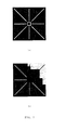
Fig. 2(a) is for an illustrative example of a star-shaped background search area the case where all criteria are valid, -
Fig. 2 (b) is an illustrative example of the same star-shaped background area whereby the intensity criteria are not valid for angles between 12 and 3 o'clock, -
Fig. 3 illustrates the segmentation of different clinical views: (a) RMLO, (b) LMLO, (c) RCC, (d) LCC, -
Fig. 4 (a) and (b) show segmentation masks, -
Fig. 4 (c) and (d) show optimally scaled images taking into account all foreground pixels, -
Fig. 4 (e) and (f) show optimally scaled images taking into account al foreground pixels from the largest object, -
Fig. 4 (g) shows a diagnostically optimally scaled image, -
Fig. 5 illustrates the need of a high performance selection method for selection of the breast region, -
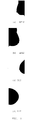
Fig. 6 shows examples of an extracted skin line, -
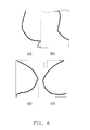
Fig. 7 illustrates the classification of points to determine the breast area, -
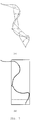
Fig. 8 illustrates the extension mechanism to derive the region of interest from the determined breast area. - While the present invention will hereinafter be described in connection with preferred embodiments thereof, it will be understood that it is not intended to limit the invention to those embodiments.
-
Figure 1 shows an example embodiment of amammography system 100. Amammography system 100 may contain aprocessor 102, operatively coupled tomemory 104.Memory 104 stores abreast window module 110 for defining breast windows onimages 120 stored onimage database 122. -
Images 120 stored onimage database 122 may comprise mammography images. Those skilled in the art will appreciate that there are different types of mammography images such as craniocaudal (CC), containing a view of a breast as taken through the top of the breast and mediolateral oblique (MLO), containing a view of a breast as taken from the center of the chest to the lateral of the breast. - Various systems may be envisaged for acquiring a digital signal representation of a radiographic image of the breast such as projection radiography image acquisition systems, echography image acquisition systems, tomosynthesis systems, computed tomography systems etc.
- Mammographic image acquisition systems typically comprise a radiation sensitive detector (e.g. x-ray radiation sensitive) for storing an image of an irradiated breast. Examples of suitable detectors are a radiographic film, a photo-stimulable phosphor screen, a direct radiography detector etc. A digital signal representation of the breast image is then obtained by reading out the image from the detector (e.g. by scanning the film, stimulating the photo-stimulable phosphor screen or reading out the direct digital detector) and eventually digitizing the read out signal. The digital signal representation of a mammographic image represents the grey value in each image pixel.
-
Image database 122stores breast images 120, and may be implemented using any database software or persistent storage method known in the art. For example,image database 122 may be implemented using Oracle®, Microsoft SQL Server® or IBM DB2® with suitably defined schemas to identify and navigateimages 120. In the exemplary embodiment,image database 122 may be part of a Picture Archiving and Communication Systems (PACS) deployment, such as those found in a hospital. Whileimage database 122 is illustrated as residing in the same memory asmammography system 100, it will be understood thatimage database 122 may be stored and accessed remotely through a network connection, for example, using a Digital Imaging and Communications in Medicine (DICOM) protocol. In such case, it will be further understood that the operations of thebreast window module 110 may be performed locally on the mammography system, remotely on the system where theimage database 122 resides, or on a third-party system configured to accessimage database 122 andmammography system 100. - According to the present invention a region of interest (ROI) is identified. This region of interest can then be displayed as large as possible to minimize the number of zoom interactions to be performed by the radiologist.
- A region of interest is determined by the steps of (1) identifying the boundary of the direct exposure area (i.e. the image area where substantially un-attenuated radiation impinges on the radiation detector) by means of a direct exposure estimation technique and (2) using this boundary to determine a skin line estimate, e.g. by subjecting it to a minimum cost path algorithm. This skin line estimate is then subjected to a shape analysis procedure and its convex part is used to determine the relevant region of interest (ROI).
- When several breast images are displayed, such as images taken at different points in time or different views of the breast, first all relevant regions of interest in these breast images are identified. Then, the display parameters are adjusted such that all relevant regions of interest of all images are displayed at the same physical scale as is described by the IHE Mammography Image Integration Profile. The largest ROI of all images is displayed as large as possible given the constraints of the display device and the same scale factor is used for display of the other ROI's. The system is preferably implemented such that a zoom out operation displays the complete images. In this way, the radiologist can easily revert to a situation with no display scale adjustment.
- When displaying the ROI found by the algorithm of the present invention, zoom in and panning operations requiring a lot of cursor movements are not necessary but replaced with a zoom out operation to make sure that the radiologist has seen all diagnostically relevant pixels. When designed properly, a zoom out operation does not require any additional panning or mouse positioning. This increases the productivity of the radiologist.
- The first step of one embodiment of the method of the present invention is a segmentation step which is applied to the digital signal representation of the rendered breast image. In this segmentation step a mask is created indicating direct exposure or background pixels. This segmentation step may also be omitted, e.g. when the gradient image derived from the breast image is used for further analysis.
- This mask is in this embodiment constructed in 2 steps: (1) an initial classification step and (2) a step for generation of a sequence of background masks from which the optimal background mask is selected. The optimal background mask is created by an iterative process in which the classification rules are strenghtened in each iteration step.
- First an initial mask of candidate background pixels is computed based on the grey pixel values in the rendered breast image. In this context the term 'rendered' refers to the image signal obtained by window/level setting and conversion to grey values. In the described exemplary embodiment the rendering of the image uses the default, most conservative, window/level settings found in the DICOM tags associated with the image. The threshold is derived from the histogram of the image and selected such that typically all background pixels are selected with some additional non-background pixels.
- Starting from this initial background mask, a sequence of further background masks is generated with a sequence of a so-called second threshold th. The sequence of the second threshold is in this embodiment the initial gray level intensity for the local intensity variability within a search region.
- As illustrated in
figure 2 , the search region is in the described embodiment defined as a star defining a number (in this embodiment: 8) radial search directions. - The difference between two successive masks is computed and used as a selection criterium for the most suitable background mask. As a measure of this selection criterium the difference is used between the number of background pixels in the 2 masks. The final background mask is the mask which shows minimum difference with the next mask in the sequence of segmentation masks.
- Alternative forms of search regions (other forms or patterns of search area) and selection criteria may be envisaged.
- Preferably each image in the sequence for a specified threshold th, is computed using the following classification rules for all pixels i:
- 1. the pixel must be a candidate background pixel in the initial background mask
- 2. there is no pixel at a distance of 2 pixels which is not an initial background pixel
- 3. no pixel is found along one of 8 search directions radiating outwards of pixel i which exceeds a varying threshold tvar over a fixed distance. tvar is initialized with the intensity value of pixel i scaled with the specified threshold th for the mask in the sequence. The varying threshold tvar is adjusted with a fraction of the central intensity value at pixel i. The fraction with which tvar is adjusted may also be dependend on the intensity value of the pixel under investigation. E.g. the update can be smaller if the pixel under investigation is smaller than the intensity value for the central pixel.
- As an additional step, small or irregular regions within the optimal background mask can be identified and removed.
- Some results of the segmentation algorithm are shown in
figure 3 . - The next step of the described embodiment of the method of the present invention is the step of determining the breast boundary.
- In previous section, an algorithm has been presented which is capable of determining the background pixels quite accurately. The presentation of the masks shown in
figure 3 suggest that determination of a ROI which covers all pixels which are labeled as non-background or foreground is suitable to determine the optimal zoom factor. In this section, some examples are shown to illustrate that a more advanced technique is required to determine the optimal zoom factor. - Consider the presence of a lead marker to identify the clinical view or the presence of a small part of the abdomen. Some examples are illustrated in
Figure 4 a-b . The resulting ROIs when using all foreground pixels are displayed inFigure 4 c-d . It is clear that the scale factor is not optimal due to the presence of some foreground pixels which are not breast related. One solution to the wrongly determined scale factor is to take into account only the foreground pixels belonging to the largest object in the segmentation mask. This strategy will generate good results for many cases but when looking atfigure 4 a and e, it is possible thatfigure 4 g might be preferred. -
Figure 5 illustrates that a more advanced selection mechanism is needed than the simple selection of the breast region in the segmentation masks because the segmentation algorithm may add some pixels which are not breast tissue to the largest object from the segmentation mask and because some diagnostically relevant parts of the image are not connected to the breast. - Skin line estimate
- In order to solve the problems identified in the previous section without modifying the segmentation algorithm, the skin line estimate is first determined and used for determining the breast contour.
- The skin line estimate is in the described embodiment identified by means of a minimal cost path technique applied to the selected optimal mask defining direct exposure pixels. In the described embodiment the cost for pixels on the edge of the direct exposure area are set to a low value e.g. 2 and the cost to traverse any other pixel is set to a high level e.g. 255. By applying standard dynamic programming techniques a path can be found from the bottom of the image located at the side of the breast to the top of the image. Some examples of extracted skin lines are shown in
Figure 6 . - Alternative methods may be envisaged for determining the skin line estimate (such as identifying border points of the largest object in the image etc).
- The above-described segmentation algorithm may be omitted, e.g. if the minimum cost path analysis is applied to the gradient image deduced from the radiation image of the breast.
- Having found the skin line, the points of the skin line are marked as a point belonging to the breast boundary by subjecting it to a shape analysis procedure. In one embodiment this shape analysis procedure is implemented by computing a measure which is an indication of convexity and evaluating this measure with regard to a given tolerance value. The measure is computed and evaluated as follows:
- 1. Take one point from the set of skin line points
- 2. Take a second point located a fixed number positions further in the set of skin line points
- 3. Connect these two points with a line
- 4. Compute the signed distance for all intermediate points on the skin line with this line
- 5. Mark both points as convex points if the minimum of the signed distance of all intermediate points of step 4 is greater than 0
- 6. Mark each point as extension point if the signed distance is larger than a defined threshold and the point is not already marked as breast point.
- The above algorithm is illustrated in
Figure 7a . - Alternatives for the above described shape analysis method may be envisaged such as analysis of curvature, of Fourier descriptors, of curvelets, Eigenshape analysis / PCA (Principal Component analysis) etc.
- The final breast boundary is then determined as the segment of convex and extension points containing the longest segment of convex points. In the example of
Figure 7b , the threshold is set to a minimum of -10. - Various strategies exist to determine a suitable ROI after having found the convex part of the skin line.
- In this section ROI definition for an MLO image is illustrated as an example.
- For all clinical views, the width of the ROI may be determined by the most extreme point of the breast boundary and the edge of the image where the breast is positioned. So the convex part of the skin line determines the width of the optimal ROI.
- Next the optimal height is to be determined. In one embodiment, the top point of the ROI (point through which a horizontal ROI delineation runs) is initially taken as the highest point of the breast boundary. This point is moved upwards as long as there are foreground pixels at the edge of the image where the breast is positioned. For MLO images, this usually means that the ROI is extended to the top edge of the image.
- The same mechanism is applied to find the bottom point of the ROI.
- In one embodiment the region of interest is a rectangle defined by the width, top edge and bottom point as determined higher.
- The technique is illustrated in
figure 8 . ForFigure 8a the ROI is extended to the top of the image because it is an MLO image and extended to the bottom of the image because there are several foreground pixels at the edge of the image below the lowest skinline point. ForFigure 8b , the extension to the bottom is not done because there are no foreground pixels at the lowest point of the skin line at the edge of the image. - One the ROI is delineated, it can be scaled for optimal viewing on the display device. Optimally the ROI is displayed as large as possible on the display device.
- In case of multiple images to be viewed, the region of interest is determined in each of the images. The largest ROI is then preferably displayed as large as possible given the constraints of the display device and all other ROI's are displayed at the same scale as described in the IHE Mammographic Image Integration Profile.
Claims (9)
- A method for defining a region of interest in a radiation image of a breast by determining a breast boundary and delineating said region of interest on the basis of the determined breast boundary characterized in that said breast boundary is obtained by determining a skin line estimate in said radiation image and subjecting it to a shape analysis procedure.
- A method according to claim 1 whereby said shape analysis procedure comprises evaluating a measure of convexity relative to a given tolerance value so as to determine convex points.
- A method according to claim 2 wherein said breast boundary is formed by the longest segment of said convex points supplemented with extension points determined by evaluating said measure of convexity with a lower tolerance value than said given tolerance value.
- A method according to claim 2 wherein points of said skin line estimate are classified as convex points belonging to said breast boundary by applying the steps of- for a first point in a set of points of said skin line estimate considering a second point further in said set- connecting the two points with an imaginary line,- computing the signed distance for all intermediary points on the skin line estimate between said first and said second point with said imaginary line,- marking said first and second points as convex points if the minimum of the signed distance of all intermediate points is greater than 0.
- A method according to claim 1 wherein said skin line estimate is obtained by- segmenting said radiation image to create a mask indicating pixels of direct exposure area, and- subjecting said mask to a minimal cost path technique.
- A method according to claim 1 wherein the width of said region of interest is determined by the most extreme point of the breast boundary and the edge of the image at the side where the breast is positioned.
- A method according to claim 1 wherein the top and bottom points of the region of interest are determined by considering the highest/lowest point of said breast boundary and moving this point upwards/downwards in said image as long as there are foreground pixels at the edge of the image where the breast is positioned.
- A computer program product adapted to carry out the method of any of the preceding claims when run on a computer.
- A computer readable medium comprising computer executable program code adapted to carry out the steps of any of claims 1 - 7.
Priority Applications (5)
| Application Number | Priority Date | Filing Date | Title |
|---|---|---|---|
| EP12155979.3A EP2629263B1 (en) | 2012-02-17 | 2012-02-17 | Method for defining a region of interest in a radiation image of a breast |
| CN201380009368.8A CN104205166B (en) | 2012-02-17 | 2013-02-12 | Method for limiting area-of-interest in the radiation image of mammary gland |
| PCT/EP2013/052750 WO2013120834A1 (en) | 2012-02-17 | 2013-02-12 | Method for defining a region of interest in a radiation image of a breast |
| BR112014015575A BR112014015575A8 (en) | 2012-02-17 | 2013-02-12 | method to define region of interest in sinus radiation imaging |
| US14/375,000 US9619888B2 (en) | 2012-02-17 | 2013-02-12 | Method for defining a region of interest in a radiation image of a breast |
Applications Claiming Priority (1)
| Application Number | Priority Date | Filing Date | Title |
|---|---|---|---|
| EP12155979.3A EP2629263B1 (en) | 2012-02-17 | 2012-02-17 | Method for defining a region of interest in a radiation image of a breast |
Publications (2)
| Publication Number | Publication Date |
|---|---|
| EP2629263A1 true EP2629263A1 (en) | 2013-08-21 |
| EP2629263B1 EP2629263B1 (en) | 2015-06-03 |
Family
ID=45656068
Family Applications (1)
| Application Number | Title | Priority Date | Filing Date |
|---|---|---|---|
| EP12155979.3A Active EP2629263B1 (en) | 2012-02-17 | 2012-02-17 | Method for defining a region of interest in a radiation image of a breast |
Country Status (5)
| Country | Link |
|---|---|
| US (1) | US9619888B2 (en) |
| EP (1) | EP2629263B1 (en) |
| CN (1) | CN104205166B (en) |
| BR (1) | BR112014015575A8 (en) |
| WO (1) | WO2013120834A1 (en) |
Cited By (2)
| Publication number | Priority date | Publication date | Assignee | Title |
|---|---|---|---|---|
| EP3094239A4 (en) * | 2014-01-15 | 2017-08-16 | Agfa HealthCare Inc. | Method and system for generating pre-scaled images for a series of mammography images |
| US10372876B2 (en) | 2017-01-20 | 2019-08-06 | Agfa Healthcare Inc. | System and method for providing breast image data |
Families Citing this family (7)
| Publication number | Priority date | Publication date | Assignee | Title |
|---|---|---|---|---|
| US20160210774A1 (en) * | 2015-01-15 | 2016-07-21 | QT Ultrasound LLC | Breast density estimation |
| CN108471995B (en) * | 2015-09-30 | 2022-03-29 | 上海联影医疗科技股份有限公司 | System and method for determining breast regions in medical images |
| JP7212372B2 (en) | 2016-09-23 | 2023-01-25 | キュアメトリックス,インコーポレイテッド | A system including an imaging device and a computing device |
| JP6833444B2 (en) * | 2016-10-17 | 2021-02-24 | キヤノン株式会社 | Radiation equipment, radiography system, radiography method, and program |
| CN109242840B (en) * | 2018-08-29 | 2021-01-12 | 上海联影医疗科技股份有限公司 | Method for detecting a beam limiter region in a breast image, method for determining a boundary in a breast image and medical device |
| WO2019228482A1 (en) | 2018-05-30 | 2019-12-05 | Shanghai United Imaging Healthcare Co., Ltd. | Systems and methods for image processing |
| US20220343513A1 (en) * | 2019-09-27 | 2022-10-27 | Hologic, Inc. | Motion detection for internal breast tissue in tomosynthesis |
Citations (5)
| Publication number | Priority date | Publication date | Assignee | Title |
|---|---|---|---|---|
| US20040161141A1 (en) * | 2003-02-19 | 2004-08-19 | Agfa-Gevaert | Method of determining the orientation of an image |
| US20060159321A1 (en) * | 2004-08-27 | 2006-07-20 | Fuji Photo Film Co., Ltd. | Breast image display apparatus and program therefor |
| US20070206844A1 (en) * | 2006-03-03 | 2007-09-06 | Fuji Photo Film Co., Ltd. | Method and apparatus for breast border detection |
| US7885443B2 (en) | 2005-11-14 | 2011-02-08 | Hologic, Inc. | Facilitating temporal comparison of medical images |
| US20110216949A1 (en) | 2010-03-08 | 2011-09-08 | Yi Yang | Method and system for defining a breast window |
Family Cites Families (3)
| Publication number | Priority date | Publication date | Assignee | Title |
|---|---|---|---|---|
| US5796862A (en) * | 1996-08-16 | 1998-08-18 | Eastman Kodak Company | Apparatus and method for identification of tissue regions in digital mammographic images |
| CN101373479A (en) * | 2008-09-27 | 2009-02-25 | 华中科技大学 | Method and system for searching computer picture of mammary gland x-ray radiography |
| CA2797238A1 (en) * | 2010-04-30 | 2011-11-03 | Vucomp, Inc. | Microcalcification detection and classification in radiographic images |
-
2012
- 2012-02-17 EP EP12155979.3A patent/EP2629263B1/en active Active
-
2013
- 2013-02-12 BR BR112014015575A patent/BR112014015575A8/en not_active IP Right Cessation
- 2013-02-12 WO PCT/EP2013/052750 patent/WO2013120834A1/en active Application Filing
- 2013-02-12 US US14/375,000 patent/US9619888B2/en active Active
- 2013-02-12 CN CN201380009368.8A patent/CN104205166B/en not_active Expired - Fee Related
Patent Citations (5)
| Publication number | Priority date | Publication date | Assignee | Title |
|---|---|---|---|---|
| US20040161141A1 (en) * | 2003-02-19 | 2004-08-19 | Agfa-Gevaert | Method of determining the orientation of an image |
| US20060159321A1 (en) * | 2004-08-27 | 2006-07-20 | Fuji Photo Film Co., Ltd. | Breast image display apparatus and program therefor |
| US7885443B2 (en) | 2005-11-14 | 2011-02-08 | Hologic, Inc. | Facilitating temporal comparison of medical images |
| US20070206844A1 (en) * | 2006-03-03 | 2007-09-06 | Fuji Photo Film Co., Ltd. | Method and apparatus for breast border detection |
| US20110216949A1 (en) | 2010-03-08 | 2011-09-08 | Yi Yang | Method and system for defining a breast window |
Non-Patent Citations (5)
| Title |
|---|
| PELIN KUS ET AL: "Fully automated gradient based breast boundary detection for digitized X-ray mammograms", COMPUTERS IN BIOLOGY AND MEDICINE, NEW YORK, NY, US, vol. 42, no. 1, 24 October 2011 (2011-10-24), pages 75 - 82, XP028342759, ISSN: 0010-4825, [retrieved on 20111109], DOI: 10.1016/J.COMPBIOMED.2011.10.011 * |
| PU JIANTAO ET AL: "An ellipse-fitting based method for efficient registration of breast masses on two mammographic views", MEDICAL PHYSICS, AIP, MELVILLE, NY, US, vol. 35, no. 2, 14 January 2008 (2008-01-14), pages 487 - 494, XP012115899, ISSN: 0094-2405, DOI: 10.1118/1.2828188 * |
| ROBERT MARTÃ ET AL: "Breast Skin-Line Segmentation Using Contour Growing", 6 June 2007, PATTERN RECOGNITION AND IMAGE ANALYSIS; [LECTURE NOTES IN COMPUTER SCIENCE;;LNCS], SPRINGER BERLIN HEIDELBERG, BERLIN, HEIDELBERG, PAGE(S) 564 - 571, ISBN: 978-3-540-72848-1, XP019095033 * |
| YAJIE SUN ET AL: "A new approach for breast skin-line estimation in mammograms", PATTERN ANALYSIS AND APPLICATIONS, SPRINGER-VERLAG, LO, vol. 9, no. 1, 4 April 2006 (2006-04-04), pages 34 - 47, XP019385827, ISSN: 1433-755X, DOI: 10.1007/S10044-006-0023-0 * |
| ZHENG BIN ET AL: "Multiview-based computer-aided detection scheme for breast masses", MEDICAL PHYSICS, AIP, MELVILLE, NY, US, vol. 33, no. 9, 16 August 2006 (2006-08-16), pages 3135 - 3143, XP012092246, ISSN: 0094-2405, DOI: 10.1118/1.2237476 * |
Cited By (2)
| Publication number | Priority date | Publication date | Assignee | Title |
|---|---|---|---|---|
| EP3094239A4 (en) * | 2014-01-15 | 2017-08-16 | Agfa HealthCare Inc. | Method and system for generating pre-scaled images for a series of mammography images |
| US10372876B2 (en) | 2017-01-20 | 2019-08-06 | Agfa Healthcare Inc. | System and method for providing breast image data |
Also Published As
| Publication number | Publication date |
|---|---|
| CN104205166B (en) | 2017-10-13 |
| US9619888B2 (en) | 2017-04-11 |
| BR112014015575A8 (en) | 2017-07-04 |
| WO2013120834A1 (en) | 2013-08-22 |
| BR112014015575A2 (en) | 2017-06-13 |
| US20150010219A1 (en) | 2015-01-08 |
| CN104205166A (en) | 2014-12-10 |
| EP2629263B1 (en) | 2015-06-03 |
Similar Documents
| Publication | Publication Date | Title |
|---|---|---|
| US9619888B2 (en) | Method for defining a region of interest in a radiation image of a breast | |
| US11158419B2 (en) | Control method and non-transitory computer-readable recording medium | |
| US11250048B2 (en) | Control method and non-transitory computer-readable recording medium for comparing medical images | |
| US7885443B2 (en) | Facilitating temporal comparison of medical images | |
| EP2807630B1 (en) | Processing and displaying a breast image | |
| US8340388B2 (en) | Systems, computer-readable media, methods, and medical imaging apparatus for the automated detection of suspicious regions of interest in noise normalized X-ray medical imagery | |
| US10123758B2 (en) | Methods and systems for determining breast density | |
| US8238630B2 (en) | Image processing apparatus and program for the same | |
| US20100135562A1 (en) | Computer-aided detection with enhanced workflow | |
| US20070274585A1 (en) | Digital mammography system with improved workflow | |
| US9615805B2 (en) | Image alignment of breast images | |
| EP2372649B1 (en) | Method and sytem for defining a breast window | |
| WO2008088478A1 (en) | Method for classifying breast tissue density | |
| JP2018061771A (en) | Image processing apparatus and image processing method | |
| US8433120B2 (en) | Method for image processing of mammographic images | |
| US20090185732A1 (en) | User interface and viewing workflow for mammography workstation | |
| US20190272640A1 (en) | Learning data creation support apparatus, learning data creation support method, and learning data creation support program | |
| JP2006325640A (en) | Method of displaying abnormal shadow candidate and medical image processing system | |
| JP2018142072A (en) | Method for controlling information terminal and program | |
| Cunningham | A Novel Mammogram Registration Algorithm for Improving Breast Cancer Detection |
Legal Events
| Date | Code | Title | Description |
|---|---|---|---|
| PUAI | Public reference made under article 153(3) epc to a published international application that has entered the european phase |
Free format text: ORIGINAL CODE: 0009012 |
|
| AK | Designated contracting states |
Kind code of ref document: A1 Designated state(s): AL AT BE BG CH CY CZ DE DK EE ES FI FR GB GR HR HU IE IS IT LI LT LU LV MC MK MT NL NO PL PT RO RS SE SI SK SM TR |
|
| AX | Request for extension of the european patent |
Extension state: BA ME |
|
| 17P | Request for examination filed |
Effective date: 20140221 |
|
| RBV | Designated contracting states (corrected) |
Designated state(s): AL AT BE BG CH CY CZ DE DK EE ES FI FR GB GR HR HU IE IS IT LI LT LU LV MC MK MT NL NO PL PT RO RS SE SI SK SM TR |
|
| GRAP | Despatch of communication of intention to grant a patent |
Free format text: ORIGINAL CODE: EPIDOSNIGR1 |
|
| INTG | Intention to grant announced |
Effective date: 20150121 |
|
| GRAS | Grant fee paid |
Free format text: ORIGINAL CODE: EPIDOSNIGR3 |
|
| GRAA | (expected) grant |
Free format text: ORIGINAL CODE: 0009210 |
|
| AK | Designated contracting states |
Kind code of ref document: B1 Designated state(s): AL AT BE BG CH CY CZ DE DK EE ES FI FR GB GR HR HU IE IS IT LI LT LU LV MC MK MT NL NO PL PT RO RS SE SI SK SM TR |
|
| REG | Reference to a national code |
Ref country code: GB Ref legal event code: FG4D |
|
| REG | Reference to a national code |
Ref country code: CH Ref legal event code: EP |
|
| REG | Reference to a national code |
Ref country code: AT Ref legal event code: REF Ref document number: 730260 Country of ref document: AT Kind code of ref document: T Effective date: 20150715 Ref country code: IE Ref legal event code: FG4D |
|
| REG | Reference to a national code |
Ref country code: DE Ref legal event code: R096 Ref document number: 602012007666 Country of ref document: DE |
|
| REG | Reference to a national code |
Ref country code: AT Ref legal event code: MK05 Ref document number: 730260 Country of ref document: AT Kind code of ref document: T Effective date: 20150603 |
|
| PG25 | Lapsed in a contracting state [announced via postgrant information from national office to epo] |
Ref country code: NO Free format text: LAPSE BECAUSE OF FAILURE TO SUBMIT A TRANSLATION OF THE DESCRIPTION OR TO PAY THE FEE WITHIN THE PRESCRIBED TIME-LIMIT Effective date: 20150903 Ref country code: ES Free format text: LAPSE BECAUSE OF FAILURE TO SUBMIT A TRANSLATION OF THE DESCRIPTION OR TO PAY THE FEE WITHIN THE PRESCRIBED TIME-LIMIT Effective date: 20150603 Ref country code: HR Free format text: LAPSE BECAUSE OF FAILURE TO SUBMIT A TRANSLATION OF THE DESCRIPTION OR TO PAY THE FEE WITHIN THE PRESCRIBED TIME-LIMIT Effective date: 20150603 Ref country code: LT Free format text: LAPSE BECAUSE OF FAILURE TO SUBMIT A TRANSLATION OF THE DESCRIPTION OR TO PAY THE FEE WITHIN THE PRESCRIBED TIME-LIMIT Effective date: 20150603 Ref country code: FI Free format text: LAPSE BECAUSE OF FAILURE TO SUBMIT A TRANSLATION OF THE DESCRIPTION OR TO PAY THE FEE WITHIN THE PRESCRIBED TIME-LIMIT Effective date: 20150603 |
|
| REG | Reference to a national code |
Ref country code: NL Ref legal event code: MP Effective date: 20150603 |
|
| REG | Reference to a national code |
Ref country code: LT Ref legal event code: MG4D |
|
| PG25 | Lapsed in a contracting state [announced via postgrant information from national office to epo] |
Ref country code: BG Free format text: LAPSE BECAUSE OF FAILURE TO SUBMIT A TRANSLATION OF THE DESCRIPTION OR TO PAY THE FEE WITHIN THE PRESCRIBED TIME-LIMIT Effective date: 20150903 Ref country code: AT Free format text: LAPSE BECAUSE OF FAILURE TO SUBMIT A TRANSLATION OF THE DESCRIPTION OR TO PAY THE FEE WITHIN THE PRESCRIBED TIME-LIMIT Effective date: 20150603 Ref country code: RS Free format text: LAPSE BECAUSE OF FAILURE TO SUBMIT A TRANSLATION OF THE DESCRIPTION OR TO PAY THE FEE WITHIN THE PRESCRIBED TIME-LIMIT Effective date: 20150603 Ref country code: GR Free format text: LAPSE BECAUSE OF FAILURE TO SUBMIT A TRANSLATION OF THE DESCRIPTION OR TO PAY THE FEE WITHIN THE PRESCRIBED TIME-LIMIT Effective date: 20150904 Ref country code: LV Free format text: LAPSE BECAUSE OF FAILURE TO SUBMIT A TRANSLATION OF THE DESCRIPTION OR TO PAY THE FEE WITHIN THE PRESCRIBED TIME-LIMIT Effective date: 20150603 |
|
| REG | Reference to a national code |
Ref country code: FR Ref legal event code: PLFP Year of fee payment: 5 |
|
| PG25 | Lapsed in a contracting state [announced via postgrant information from national office to epo] |
Ref country code: EE Free format text: LAPSE BECAUSE OF FAILURE TO SUBMIT A TRANSLATION OF THE DESCRIPTION OR TO PAY THE FEE WITHIN THE PRESCRIBED TIME-LIMIT Effective date: 20150603 |
|
| PG25 | Lapsed in a contracting state [announced via postgrant information from national office to epo] |
Ref country code: PT Free format text: LAPSE BECAUSE OF FAILURE TO SUBMIT A TRANSLATION OF THE DESCRIPTION OR TO PAY THE FEE WITHIN THE PRESCRIBED TIME-LIMIT Effective date: 20151006 Ref country code: IS Free format text: LAPSE BECAUSE OF FAILURE TO SUBMIT A TRANSLATION OF THE DESCRIPTION OR TO PAY THE FEE WITHIN THE PRESCRIBED TIME-LIMIT Effective date: 20151003 Ref country code: CZ Free format text: LAPSE BECAUSE OF FAILURE TO SUBMIT A TRANSLATION OF THE DESCRIPTION OR TO PAY THE FEE WITHIN THE PRESCRIBED TIME-LIMIT Effective date: 20150603 Ref country code: RO Free format text: LAPSE BECAUSE OF NON-PAYMENT OF DUE FEES Effective date: 20150603 Ref country code: PL Free format text: LAPSE BECAUSE OF FAILURE TO SUBMIT A TRANSLATION OF THE DESCRIPTION OR TO PAY THE FEE WITHIN THE PRESCRIBED TIME-LIMIT Effective date: 20150603 Ref country code: SK Free format text: LAPSE BECAUSE OF FAILURE TO SUBMIT A TRANSLATION OF THE DESCRIPTION OR TO PAY THE FEE WITHIN THE PRESCRIBED TIME-LIMIT Effective date: 20150603 |
|
| REG | Reference to a national code |
Ref country code: DE Ref legal event code: R097 Ref document number: 602012007666 Country of ref document: DE |
|
| PLBE | No opposition filed within time limit |
Free format text: ORIGINAL CODE: 0009261 |
|
| STAA | Information on the status of an ep patent application or granted ep patent |
Free format text: STATUS: NO OPPOSITION FILED WITHIN TIME LIMIT |
|
| PG25 | Lapsed in a contracting state [announced via postgrant information from national office to epo] |
Ref country code: IT Free format text: LAPSE BECAUSE OF FAILURE TO SUBMIT A TRANSLATION OF THE DESCRIPTION OR TO PAY THE FEE WITHIN THE PRESCRIBED TIME-LIMIT Effective date: 20150603 Ref country code: DK Free format text: LAPSE BECAUSE OF FAILURE TO SUBMIT A TRANSLATION OF THE DESCRIPTION OR TO PAY THE FEE WITHIN THE PRESCRIBED TIME-LIMIT Effective date: 20150603 |
|
| 26N | No opposition filed |
Effective date: 20160304 |
|
| PG25 | Lapsed in a contracting state [announced via postgrant information from national office to epo] |
Ref country code: BE Free format text: LAPSE BECAUSE OF NON-PAYMENT OF DUE FEES Effective date: 20160229 Ref country code: SI Free format text: LAPSE BECAUSE OF FAILURE TO SUBMIT A TRANSLATION OF THE DESCRIPTION OR TO PAY THE FEE WITHIN THE PRESCRIBED TIME-LIMIT Effective date: 20150603 |
|
| PG25 | Lapsed in a contracting state [announced via postgrant information from national office to epo] |
Ref country code: LU Free format text: LAPSE BECAUSE OF FAILURE TO SUBMIT A TRANSLATION OF THE DESCRIPTION OR TO PAY THE FEE WITHIN THE PRESCRIBED TIME-LIMIT Effective date: 20160217 Ref country code: MC Free format text: LAPSE BECAUSE OF FAILURE TO SUBMIT A TRANSLATION OF THE DESCRIPTION OR TO PAY THE FEE WITHIN THE PRESCRIBED TIME-LIMIT Effective date: 20150603 |
|
| REG | Reference to a national code |
Ref country code: CH Ref legal event code: PL |
|
| PG25 | Lapsed in a contracting state [announced via postgrant information from national office to epo] |
Ref country code: LI Free format text: LAPSE BECAUSE OF NON-PAYMENT OF DUE FEES Effective date: 20160229 Ref country code: CH Free format text: LAPSE BECAUSE OF NON-PAYMENT OF DUE FEES Effective date: 20160229 |
|
| REG | Reference to a national code |
Ref country code: IE Ref legal event code: MM4A |
|
| PG25 | Lapsed in a contracting state [announced via postgrant information from national office to epo] |
Ref country code: BE Free format text: LAPSE BECAUSE OF FAILURE TO SUBMIT A TRANSLATION OF THE DESCRIPTION OR TO PAY THE FEE WITHIN THE PRESCRIBED TIME-LIMIT Effective date: 20150603 |
|
| REG | Reference to a national code |
Ref country code: FR Ref legal event code: PLFP Year of fee payment: 6 |
|
| PG25 | Lapsed in a contracting state [announced via postgrant information from national office to epo] |
Ref country code: IE Free format text: LAPSE BECAUSE OF NON-PAYMENT OF DUE FEES Effective date: 20160217 |
|
| PG25 | Lapsed in a contracting state [announced via postgrant information from national office to epo] |
Ref country code: NL Free format text: LAPSE BECAUSE OF FAILURE TO SUBMIT A TRANSLATION OF THE DESCRIPTION OR TO PAY THE FEE WITHIN THE PRESCRIBED TIME-LIMIT Effective date: 20150603 Ref country code: SE Free format text: LAPSE BECAUSE OF FAILURE TO SUBMIT A TRANSLATION OF THE DESCRIPTION OR TO PAY THE FEE WITHIN THE PRESCRIBED TIME-LIMIT Effective date: 20150603 |
|
| PG25 | Lapsed in a contracting state [announced via postgrant information from national office to epo] |
Ref country code: MT Free format text: LAPSE BECAUSE OF FAILURE TO SUBMIT A TRANSLATION OF THE DESCRIPTION OR TO PAY THE FEE WITHIN THE PRESCRIBED TIME-LIMIT Effective date: 20150603 |
|
| REG | Reference to a national code |
Ref country code: FR Ref legal event code: PLFP Year of fee payment: 7 |
|
| PG25 | Lapsed in a contracting state [announced via postgrant information from national office to epo] |
Ref country code: SM Free format text: LAPSE BECAUSE OF FAILURE TO SUBMIT A TRANSLATION OF THE DESCRIPTION OR TO PAY THE FEE WITHIN THE PRESCRIBED TIME-LIMIT Effective date: 20150603 Ref country code: CY Free format text: LAPSE BECAUSE OF FAILURE TO SUBMIT A TRANSLATION OF THE DESCRIPTION OR TO PAY THE FEE WITHIN THE PRESCRIBED TIME-LIMIT Effective date: 20150603 Ref country code: HU Free format text: LAPSE BECAUSE OF FAILURE TO SUBMIT A TRANSLATION OF THE DESCRIPTION OR TO PAY THE FEE WITHIN THE PRESCRIBED TIME-LIMIT; INVALID AB INITIO Effective date: 20120217 |
|
| PG25 | Lapsed in a contracting state [announced via postgrant information from national office to epo] |
Ref country code: TR Free format text: LAPSE BECAUSE OF FAILURE TO SUBMIT A TRANSLATION OF THE DESCRIPTION OR TO PAY THE FEE WITHIN THE PRESCRIBED TIME-LIMIT Effective date: 20150603 Ref country code: MK Free format text: LAPSE BECAUSE OF FAILURE TO SUBMIT A TRANSLATION OF THE DESCRIPTION OR TO PAY THE FEE WITHIN THE PRESCRIBED TIME-LIMIT Effective date: 20150603 Ref country code: MT Free format text: LAPSE BECAUSE OF FAILURE TO SUBMIT A TRANSLATION OF THE DESCRIPTION OR TO PAY THE FEE WITHIN THE PRESCRIBED TIME-LIMIT Effective date: 20160229 |
|
| REG | Reference to a national code |
Ref country code: GB Ref legal event code: 732E Free format text: REGISTERED BETWEEN 20180816 AND 20180822 |
|
| REG | Reference to a national code |
Ref country code: DE Ref legal event code: R081 Ref document number: 602012007666 Country of ref document: DE Owner name: AGFA NV, BE Free format text: FORMER OWNER: AGFA HEALTHCARE, MORTSEL, BE |
|
| PG25 | Lapsed in a contracting state [announced via postgrant information from national office to epo] |
Ref country code: AL Free format text: LAPSE BECAUSE OF FAILURE TO SUBMIT A TRANSLATION OF THE DESCRIPTION OR TO PAY THE FEE WITHIN THE PRESCRIBED TIME-LIMIT Effective date: 20150603 |
|
| PGFP | Annual fee paid to national office [announced via postgrant information from national office to epo] |
Ref country code: FR Payment date: 20230209 Year of fee payment: 12 |
|
| PGFP | Annual fee paid to national office [announced via postgrant information from national office to epo] |
Ref country code: GB Payment date: 20230209 Year of fee payment: 12 Ref country code: DE Payment date: 20230209 Year of fee payment: 12 |
|
| REG | Reference to a national code |
Ref country code: DE Ref legal event code: R081 Ref document number: 602012007666 Country of ref document: DE Owner name: AGFA HEALTHCARE NV, BE Free format text: FORMER OWNER: AGFA NV, MORTSEL, BE |
|
| REG | Reference to a national code |
Ref country code: GB Ref legal event code: 732E Free format text: REGISTERED BETWEEN 20231207 AND 20231213 |