EP1681012A1 - Insert support system - Google Patents
Insert support system Download PDFInfo
- Publication number
- EP1681012A1 EP1681012A1 EP04799438A EP04799438A EP1681012A1 EP 1681012 A1 EP1681012 A1 EP 1681012A1 EP 04799438 A EP04799438 A EP 04799438A EP 04799438 A EP04799438 A EP 04799438A EP 1681012 A1 EP1681012 A1 EP 1681012A1
- Authority
- EP
- European Patent Office
- Prior art keywords
- route
- image
- vbs
- point
- setting
- Prior art date
- Legal status (The legal status is an assumption and is not a legal conclusion. Google has not performed a legal analysis and makes no representation as to the accuracy of the status listed.)
- Granted
Links
Images


Classifications
-
- A—HUMAN NECESSITIES
- A61—MEDICAL OR VETERINARY SCIENCE; HYGIENE
- A61B—DIAGNOSIS; SURGERY; IDENTIFICATION
- A61B1/00—Instruments for performing medical examinations of the interior of cavities or tubes of the body by visual or photographical inspection, e.g. endoscopes; Illuminating arrangements therefor
- A61B1/00002—Operational features of endoscopes
- A61B1/00004—Operational features of endoscopes characterised by electronic signal processing
- A61B1/00009—Operational features of endoscopes characterised by electronic signal processing of image signals during a use of endoscope
-
- A—HUMAN NECESSITIES
- A61—MEDICAL OR VETERINARY SCIENCE; HYGIENE
- A61B—DIAGNOSIS; SURGERY; IDENTIFICATION
- A61B34/00—Computer-aided surgery; Manipulators or robots specially adapted for use in surgery
- A61B34/10—Computer-aided planning, simulation or modelling of surgical operations
-
- A—HUMAN NECESSITIES
- A61—MEDICAL OR VETERINARY SCIENCE; HYGIENE
- A61B—DIAGNOSIS; SURGERY; IDENTIFICATION
- A61B10/00—Other methods or instruments for diagnosis, e.g. instruments for taking a cell sample, for biopsy, for vaccination diagnosis; Sex determination; Ovulation-period determination; Throat striking implements
- A61B10/02—Instruments for taking cell samples or for biopsy
-
- A—HUMAN NECESSITIES
- A61—MEDICAL OR VETERINARY SCIENCE; HYGIENE
- A61B—DIAGNOSIS; SURGERY; IDENTIFICATION
- A61B34/00—Computer-aided surgery; Manipulators or robots specially adapted for use in surgery
- A61B34/10—Computer-aided planning, simulation or modelling of surgical operations
- A61B2034/101—Computer-aided simulation of surgical operations
- A61B2034/105—Modelling of the patient, e.g. for ligaments or bones
-
- A—HUMAN NECESSITIES
- A61—MEDICAL OR VETERINARY SCIENCE; HYGIENE
- A61B—DIAGNOSIS; SURGERY; IDENTIFICATION
- A61B34/00—Computer-aided surgery; Manipulators or robots specially adapted for use in surgery
- A61B34/20—Surgical navigation systems; Devices for tracking or guiding surgical instruments, e.g. for frameless stereotaxis
- A61B2034/2046—Tracking techniques
- A61B2034/2065—Tracking using image or pattern recognition
-
- A—HUMAN NECESSITIES
- A61—MEDICAL OR VETERINARY SCIENCE; HYGIENE
- A61B—DIAGNOSIS; SURGERY; IDENTIFICATION
- A61B34/00—Computer-aided surgery; Manipulators or robots specially adapted for use in surgery
- A61B34/30—Surgical robots
- A61B2034/301—Surgical robots for introducing or steering flexible instruments inserted into the body, e.g. catheters or endoscopes
-
- A—HUMAN NECESSITIES
- A61—MEDICAL OR VETERINARY SCIENCE; HYGIENE
- A61B—DIAGNOSIS; SURGERY; IDENTIFICATION
- A61B34/00—Computer-aided surgery; Manipulators or robots specially adapted for use in surgery
- A61B34/25—User interfaces for surgical systems
Definitions
- the present invention relates to an insertion support system for supporting insertion of an endoscope.
- diagnosis using images has been widely performed; for example, diagnosis of a target portion has been performed using three-dimensional image data obtained within a subject by capturing tomograms of the subject using an X-ray CT (Computed Tomography) apparatus or the like.
- X-ray CT Computed Tomography
- spiral consecutive scan is performed regarding a three-dimensional region of a subject by consecutively forwarding the subject in the body-axial direction while consecutively rotating X-ray radiation and detection, thereby creating a three-dimensional image from consecutive sliced tomograms of the three-dimensional region.
- three-dimensional images is three-dimensional images of the bronchial tube of the lungs.
- the three-dimensional images of the bronchial tube are used for three-dimensionally recognizing the position of an abnormal portion where lung cancer or the like is suspected, for example.
- sampling of tissue samples is performed by inserting a bronchoscope and projecting a biopsy needle or biopsy forceps or the like from the tip thereof.
- a device for navigating a bronchoscope to the target portion has been proposed by creating a three-dimensional image of a duct within the subject based on the image data of a three-dimensional region of the subject, obtaining the route to the target point along the duct on the three-dimensional image, creating a virtual endoscopic image of the duct along the route based on the image data, and displaying the virtual endoscopic image.
- this conventional device presents a problem in that living tissue serving as the target portion generally has an expanse, so even if a biopsy position is specified when performing biopsy, the insertion route to the biopsy position is not determined uniquely, and multiple insertion routes can be set, but it is difficult for the conventional devices to determine the most appropriate route from the multiple insertion routes when performing insertion support.
- the present invention has been made in light of the above situations, and provides an insertion support system capable of verifying the most appropriate insertion route when performing insertion support, of the multiple insertion routes.
- An insertion support system comprises virtual image generating means for generating a virtual image of the body cavity path within a subject based on the image data of a three-dimensional region of the subject, route starting-point setting means for setting the starting-point of an insertion route of an endoscope to the body cavity path within the subject, region-of-interest setting means for setting the region of a portion of interest within the subject, route extracting means for extracting the multiple insertion routes to the region of the portion of interest from the starting-point, and route verifying means for verifying the multiple insertion routes extracted by the route extracting means.
- the insertion support system according to the present invention has an advantage wherein the most appropriate insertion route of multiple insertion routes can be verified when performing insertion support.
- a bronchial tube insertion support system 1 As shown in Fig. 1, a bronchial tube insertion support system 1 according to the present embodiment has a bronchoscope apparatus 3 and an insertion support device 5.
- the insertion support device 5 generates a virtual endoscopic image within a bronchial tube (hereinafter, referred to as VBS image) based on CT image data, and also synthesizes the endoscope image obtained by the bronchoscope apparatus 3 (hereinafter, referred to as live image) and the VBS image to display this on a monitor 6, thereby performing insertion support of the bronchoscope apparatus 3 to the bronchial tube.
- VBS image virtual endoscopic image within a bronchial tube
- the bronchoscope apparatus has a bronchoscope having image capturing means, a light source for supplying illumination light to the bronchoscope, a camera control unit for subjecting an image-captured signal from the bronchoscope to signal processing, and so forth, inserts the bronchoscope in the bronchial tube within a patient to capture an image within the bronchial tube, subjects the target tissue of the end of the bronchial tube to biopsy, and also synthesizes a live image and a VBS image to display this on a monitor 7.
- an input unit 8 made up of a touch panel is provided, and a user can operate the input unit 8 made up of a touch panel while performing insertion procedure.
- the insertion support device 5 has a CT-image-data capturing unit 11 for capturing the three-dimensional image data generated at an unshown known CT device for capturing X-ray tomograms of a patient via a portable storage medium such as a MO (Magnetic Optical disk) device, or DVD (Digital Versatile Disk) device, a CT-image-data storing unit 12 for storing CT image data captured by the CT-image-data capturing unit 11, an MPR-image generating unit 13 for generating MPR images (multistage restructuring images: coronal image, axial image, and sagittal image) based on the CT image data stored in the CT-image-data storing unit 12, a route setting unit 14 for generating a later-described route setting screen having the MPR image generated by the MPR-image generating unit to set a support route of the bronchoscope apparatus 3 to the bronchial tube (hereinafter, simply referred to as route), a VBS-image generating unit 15 serving as virtual image generating means for
- the bronchoscope apparatus 3 receives the VBS image and thumbnail VBS image from the image processing unit 17 of the insertion support device 5 to synthesize these with a live image, displays the screen equivalent to the insertion support screen, which the insertion support device 5 displays on the monitor 6, on the monitor 7, and also outputs the input information from the input unit 8 made up of the touch sensor of the monitor 7 to the image processing unit 17 of the insertion support device 5.
- CT-image-data storing unit 12 and the VBS-image storing unit 16 may be configured of one hard disk, and also the MPR-image generating unit 13, route setting unit 14, VBS-image generating unit 15, and image processing unit 17 may be configured of one arithmetic processing circuit.
- CT-image-data capturing unit 11 captures CT image data via a portable storage medium such as an MO or DVD, but in the event that a CT device or in-hospital server storing CT image data is connected to an in-hospital LAN, CT image data may be captured via the in-hospital LAN by comprising the CT-image-data capturing unit 11 using an interface circuit capable of connecting to the in-hospital LAN.
- the route setting unit 14 has a route starting-point setting function 14a serving as route starting-point setting means for setting the insertion starting-point of the bronchial tube, a region-of-interest setting function 14b serving as region-of-interest setting means for setting a region of interest serving as the insertion end-point of the bronchial tube, a route extracting function 14c serving as route extracting means for extracting an insertion route to the insertion end-point from the insertion starting-point, and a route verifying function 14d serving as route verifying means for performing verification of the extracted insertion route. Detailed description of these functions will be given later.
- the insertion support device 5 captures the CT image data of a patient generated at the CT device using the CT-image-data capturing unit 11 in step S1, and stores the captured CT image data in the CT-image-data storing unit 12 in step S2.
- step S3 the route setting unit 14 displays a route setting screen 21 such as shown in Fig. 4 on the monitor 6, and the user selects patient information at a patient information tag screen 22 on the route setting screen 21.
- a coronal image 23a, axial image 23b, and sagittal image 23c serving as MPR images (hereinafter, simply referred to as MPR images 23) made up of three different multistage restructuring images of the selected patient are generated, and these coronal image 23a, axial image 23b, and sagittal image 23c are displayed on the route setting screen 21 in step S5.
- a VBS image display area 23d for displaying a VBS image is provided on the route setting screen 21 .
- selection of patient information at the patient information tag screen 22 is performed by the user inputting a patient ID for identifying a patient through the input device 19.
- step S6 upon the user selecting a route setting tag 24 (see Fig. 4) on the route setting screen 21 through the input device 19, a route setting tag screen 25 such as shown in Fig. 5 is displayed on the route setting screen 21, later-described route setting processing is performed, and the insertion support route of the bronchoscope in the bronchial tube is set.
- the VBS-image generating unit 15 Upon the insertion support route having been set, the VBS-image generating unit 15 generates the VBS images for each frame wherein all of the routes set continue in step S7, and stores the generated VBS images in the VBS-image storing unit 16 in step S8.
- insertion support preparation by the insertion support device 4 is completed at the time of observation and treatment using the bronchoscope.
- the route setting processing in step S6 starts. Specifically, the route starting-point setting function 14a of the route setting unit 14 displays a starting-point input-instruction window 31 for prompting the user to input the starting point of a route such as shown in Fig. 6 on the route setting screen 21, and the user sets a starting point 71 on one tomogram of the MPR images 23 using a cursor 30 on the route setting screen 21.
- the starting point 71 Upon the user setting the starting point 71, the starting point 71 is set on the corresponding positions of the two tomograms of the other MPR images 23, and also the VBS image at the starting point 71 is displayed on the VBS image display area 23d, and then a biopsy area input-instruction window 32 for prompting the user to set a biopsy area 72 serving as the end point of a route such as shown in Fig. 7 is displayed on the route setting screen 21.
- the user two-dimensionally traces and sets the biopsy area 72 serving as a region of interest on any two tomograms of the MPR images 23 by operating the cursor 30 on the route setting screen 21 in this Fig. 6.
- the number of the biopsy areas 72 is not restricted to one, the multiple biopsy areas 72 can be specified, and Fig. 7 illustrates a state in which two biopsy areas 72a and 72b are specified.
- the route extracting function 14c of the route setting unit 14 displays a route number setting window 33 for setting the number of routes to be searched per one biopsy area 72 such as shown in Fig. 8 on the route setting screen 21. Multiple approach routes to the biopsy area 72 to be navigated are searched by setting the number of search routes per one biopsy area 72.
- the route extracting function 14c searches the routes in accordance with processing in Fig. 9.
- step S11 the number of the biopsy areas 72 set in step S11 is detected, a number n of search routes is read in step S12, and the position of the starting point 71 is read in step S13.
- step S14 the center-of-gravity position of each biopsy area 72 is extracted in step S14, r representing the radius of a sphere centered on the center-of-gravity position is set to an initial value r0 in step S15, and then the inside of the sphere having the radius r is specified as a search area in step S16.
- step S17 Whether or not there is the bronchial tube within the search area is determined in step S17, and in the event that there is the bronchial tube, a route candidate wherein the position thereof is taken as an end point is determined in step S18.
- step S19 Upon the route candidate being determined, whether or not the route candidate determined in step S19 has been registered is determined, and in the event of the route candidate being unregistered, a route name based on the branch name from the starting point to the end point is generated in step S20 and this is registered as a support route.
- step S21 whether or not the number of routes registered is less than the n number of routes read in step S12 is determined.
- step S17 the search area is enlarged by performing r + ⁇ r in step S22, and returns to step S16.
- step S23 Upon the number of routes registered reaching the n number of routes read in step S2, in step S23 whether or not all of the biopsy areas set have been searched is determined, and in the event of all of the biopsy areas having been searched, the processing ends, and in the event of unsearched biopsy areas having been left, the center-of-gravity position of the next biopsy area is extracted in step S23, and returns to step S15.
- the center of gravity 103 of the biopsy area 72 is extracted.
- the circle centered on this center of gravity 103 is taken as a search area 104
- the search area 104 is enlarged until the bronchial tube is positioned within the search area 104
- the point where the bronchial tube is positioned first within the search area 104 is taken as an end point 105
- a first route candidate 106 connecting the starting point 71 and this end point 105 as shown in Fig. 12 is determined, and in the event of this first route candidate 106 having been unregistered, this is registered as a first support route.
- the route name at this time is named based on a branch name which this route passes through.
- the radius of the search area 104 centered on the center of gravity 103 is increased to enlarge the search area 104, the point where the bronchial tube is positioned next within the search area 104 is taken as an end point 107, a second route candidate 108 connecting the starting point 71 and this end point 107 as shown in Fig. 14 is determined, and in the event of this second route candidate 108 having been unregistered, this is registered as a second support route.
- the second route candidate 108 is different from the first support route in Fig. 12, so the second route candidate 108 becomes the second support route.
- the route name at this time is also named based on a branch name which this route passes through.
- the number of routes is three, so in the same way, upon the second support route being determined, as shown in Fig. 15, the radius of the search area 104 centered on the center of gravity 103 is further increased to enlarge the search area 104, the point where the bronchial tube is positioned next within the search area 104 is taken as an end point 109, a third route candidate 110 connecting the starting point 71 and this end point 109 as shown in Fig. 16 is determined, and in the event of this third route candidate 110 having been unregistered, this is registered as a third support route.
- the third route candidate 110 is different from the first and second support routes, so the third route candidate 110 becomes the third support route.
- the route name at this time is also named based on a branch name which this route passes through.
- the same number of support routes as the specified number of routes can be set. All of the biopsy areas 72 are subjected to the above processing, thereby setting the same number of support routes as the number of routes specified for each of the biopsy areas 72.
- the route verifying function 14d of the route setting unit 14 displays a route verification window 200 such as shown in Fig. 17 on the monitor 6.
- the route verification window 200 has a coronal image 23a, an axial image 23b, a sagittal image 23c, serving as MPR images, a VBS image display area 23d for displaying a VBS image, checkboxes 201 for specifying the multiple support routes set, and a reproduction button 202 for reproducing the VBS image to be displayed on the VBS image display area 23d as a moving image along a support route.
- the multiple support routes which have been set are displayed, and in the case of Fig. 17, three support routes are displayed.
- the route verifying function 14d displays a pointer 210 on the starting-point position of the first support route on the coronal image 23a, axial image 23b, and sagittal image 23c, and also displays the VBS image of the first support route position where this pointer 210 is positioned on the VBS image display area 23d.
- the pointer 210 is capable of moving on the first support route alone, and character data "1" indicating that this pointer is the pointer of the first support route is also displayed near the pointer 210.
- the VBS image to be displayed on the VBS image display area 23d is changed to the VBS image at the position where the moved pointer 210 is positioned on the position of the first support route. Note that transition is made from the VBS image in Fig. 18 to the VBS image in Fig. 19, as a moving image of the VBS image as the pointer 210 moves.
- the pointer 210 moves from the starting-point position to the end-point position along the support route, while displaying the VBS image on the VBS image display area 23d as a moving image, and finally the VBS image to be displayed on the VBS image display area 23d becomes the VBS image at the end-point position as shown in Fig. 21.
- the pointer 210 moves from that position to the end-point position along the support route, while displaying the VBS image on the VBS image display area 23d as a moving image, and finally the VBS image to be displayed on the VBS image display area 23d becomes the VBS image at the end-point position as shown in Fig. 21.
- the VBS images on the first support route can be confirmed, so that verification can be made regarding whether or not the first support route is a suitable route.
- multiple support routes can be verified simultaneously. That is to say, as shown in Fig. 22, for example, upon the user checking all of the three support routes at the checkboxes 201, the pointer 210 is pointed at the starting-point position of the support routes on the coronal image 23a, axial image 23b, and sagittal image 23c, but the starting-point positions of the three support routes are the same, so the number of the pointers 210 to be displayed is only one. At this time, however, character data "1", "2", and "3" which indicate the first through third support route pointers are also displayed near the pointer 210.
- VBS image display area 23d1 three of a VBS image display area 23d1, VBS image display area 23d2, and VBS image display area 23d3 are provided for displaying the VBS image of each route instead of the VBS image display area 23d.
- VBS image display area 23d1, VBS image display area 23d2, and VBS image display area 23d3 the VBS image at the position where the pointer 210 is positioned on each route is displayed.
- the pointer 210 on each route is positioned at the starting-point position, so the VBS images to be displayed on the first-insertion-route VBS image display area 23d1, the second-insertion-route VBS image display area 23d2, and the third-insertion-route VBS image display area 23d3 are the same, and the VBS image at the starting-point position is displayed.
- the third insertion route pointer 210 is pointed on the third insertion route, and also the VBS image where the third insertion route pointer 210 is positioned is displayed on the VBS image display area 23d3.
- the VBS image at the starting-point position is displayed without any change.
- the respective pointers 210 move along all of the insertion routes, while displaying the VBS images as a moving image on the first-insertion-route VBS image display area 23d1, second-insertion-route VBS image display area 23d2, and third-insertion-route VBS image display area 23d3, and finally the VBS images to be displayed on the first-insertion-route VBS image display area 23d1, second-insertion-route VBS image display area 23d2, and third-insertion-route VBS image display area 23d3 become the VBS image at the end-point position, as shown in Fig. 21.
- a fourth-insertion-route VBS image display area 23d4 is displayed, but the actions at that time are the same as those in Fig. 22 through Fig. 24.
- a VBS display frame 220 is displayed in the route verification window 200.
- this VBS display frame 220 has checkboxes 221 for specifying an arbitrary support route within six support routes for example, and a VBS image display portion 222 made up of VBS image display areas for displaying VBS images in the case in which the support routes selected at the checkboxes 221 are four or less.
- a VBS image display portion 222 made up of VBS image display areas for displaying VBS images in the case in which the support routes selected at the checkboxes 221 are four or less.
- the display method of VBS images is the same as that in Fig. 22 through Fig. 24.
- a scroll bar 223 is displayed on the VBS image display portion 222.
- the number of the VBS image display areas to be displayed on the VBS image display portion 222 is restricted to four, but the VBS images of the six VBS image display areas can be confirmed sequentially by operating the scroll bar 223.
- Fig. 28 illustrates a state in which the VBS images on the first through fourth insertion routes can be displayed
- Fig. 29 illustrates a state in which the VBS images on the third through sixth insertion routes can be displayed.
- a pop-up window 224 is displayed on the VBS display frame 220, and the user can select an insertion route on the pop-up window 224, and in this case, restricting the number of selections to four or less enables the display size of the VBS images to be set to a confirmable size.
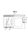
- the route verifying function 14d of the route setting unit 14 displays a route verification window 200 such as shown in Fig. 31 on the monitor 6.
- the route verifying function 14d generates a bronchial tube thinning model image 301 by thinning a bronchial tube three-dimensional image 300 based on CT image data such as shown in Fig. 32, and the route verification window 200 can display the thinning model image 301 on a three-dimensional image display area 310 instead of the coronal image 23a, axial image 23b, and sagittal image 23c, shown in Fig. 31.
- a rotate-counterclockwise button 311 and a rotate-clockwise button 312 for rotating the thinning model image 301 around the C axis are provided underneath this three-dimensional image display area 310, and the others are the same as Fig. 17.
- the pointer 210 is pointed at the starting-point position on the thinning model image 301, and the VBS image of the first insertion route at the starting-point position is displayed on the VBS image display area 23d.
- the thinning model image 301 rotates counterclockwise or clockwise around the C axis for the period corresponding to clicking.
- the VBS image on the VBS image display area 23d is an image from the fixed starting-point, so upon the thinning model image 301 rotating around the C axis, the VBS image rotates in sync with rotation thereof.
- the VBS image can be confirmed by arbitrarily rotating the VBS image within the bronchial tube.
- the pointer 210 on the thinning model image 301 can be moved to the position on an arbitrary insertion route, and in this case, as described above, while the VBS image is changing as a movie image, the VBS image of the insertion route where the pointer 210 is positioned is displayed on the VBS image display area 23d.
- the pointer 210 positioned at the starting-point position as shown in Fig. 35 moves to the end-point position as shown in Fig. 36, and at this time, the VBS image is displayed on the VBS image display area 23d as a moving image in sync with this movement of the pointer 210.
- the respective pointers 210 are displayed on the thinning model image 301.
- display of the VBS images is the same as in the case of operating the pointer 210 on an insertion route on an MPR image, and the route verification window 200 in a format shown in Fig. 37 is used for up to four insertion routes.
- the VBS display frame 220 is displayed on the route verification window 200, but this VBS display frame 220 has been described above, so description thereof will be omitted.
- an insertion support screen 51 such as shown in Fig. 39 is displayed on the monitor 7. Note that the same insertion support screen 51 as the monitor 7 is also displayed on the monitor 6.
- This insertion support screen 51 has an endoscope live image display area 52 for displaying the live image from the bronchoscope apparatus 3, a VBS image display area 53 for displaying a VBS image 53a, and a branch thumbnail VBS image area 54 for compressing the VBS image 53a at all of the branches of a route, and displaying these as reduced branch thumbnail VBS images 54(a) through 54(j), and the VBS image 53a serving as a virtual image corresponding to the branch point where the live image is positioned is displayed on the VBS image display area 53.
- the frame of the same branch thumbnail VBS image as the VBS image 53a to be displayed on the VBS image display area 53 is displayed with a thick frame or in color, so can be distinguished from the other branch thumbnail VBS images, and the user can readily recognize which branch the VBS image to be displayed on the VBS image display area 53 belongs to.
- the second embodiment is almost the same as the first embodiment, so only different points will be described, the same configurations are appended with the same reference numerals, and the description thereof will be omitted.
- the route verifying function 14d of the route setting unit 14 has a route setting simulation function.
- the route setting simulation function compares the similarities between the structure of the bronchial tube of a patient serving as the target and the past bronchial tube structure data following completion of route setting, and in the event that the CT-image-data storing unit 12 has bronchial tube structure data similar to the present target by more than a predetermined similarity, and also the VBS image storing unit 16 has operating data on the insertion support screen 51 when insertion support has a similar end-point, the route setting simulation function displays the effect, enables insertion support simulation using the bronchial tube structure data and operating data to be performed, and also allows the operator to more appropriately perform verification of a route which has been set.
- the route verifying function 14d analyzes the bronchial tube structure of the target patient stored in the CT-image-data storing unit 12 in step S101, and searches the bronchial tube structure data having a similar structure from a database made up of the past bronchial tube structure data built on the CT-image-data storing unit 12 in step S102.
- step S103 the route verifying function 14d determines whether or not there is a past bronchial tube structure data similar to that of the target patient by more than a predetermined similarity, and in the event that there is the past bronchial tube structure data, the route verifying function 14d displays the route range satisfying the condition of more than a predetermined similarity in step S104.
- Examples of a display method include, for example, route range display on each image such as:
- a matched route range 1001 and an unmatched route range 1002 are displayed with a different color on the route toward an end-point range 1000.
- the route verifying function 14d determines whether or not a simulation using a VBS image based on the past bronchial tube structure data as to the route displayed in step S105 is to be performed, and upon the route verifying function 14d performing the simulation, the route verifying function 14d performs the simulation using comparative display between the VBS image of the target patient and the past VBS image within the matched route range like the VBS image such as shown in Fig. 44 in step S106, and registers the past bronchial tube structure data into the database of the CT-image-data storing unit 12 as simulation target data, and ends the processing in step S107.
- Fig. 44 shows a display screen made up of a first VBS image display area 1010 for displaying the VBS image of the target patient (current data), a second VBS image display area 1011 for displaying similar VBS image (past data), and a slider bar 1012 for specifying the display frame of these VBS images.
Abstract
Description
- The present invention relates to an insertion support system for supporting insertion of an endoscope.
- In recent years, diagnosis using images has been widely performed; for example, diagnosis of a target portion has been performed using three-dimensional image data obtained within a subject by capturing tomograms of the subject using an X-ray CT (Computed Tomography) apparatus or the like.
- With CT apparatuses, spiral consecutive scan (helical scan) is performed regarding a three-dimensional region of a subject by consecutively forwarding the subject in the body-axial direction while consecutively rotating X-ray radiation and detection, thereby creating a three-dimensional image from consecutive sliced tomograms of the three-dimensional region.
- One example of such three-dimensional images is three-dimensional images of the bronchial tube of the lungs. The three-dimensional images of the bronchial tube are used for three-dimensionally recognizing the position of an abnormal portion where lung cancer or the like is suspected, for example. In order to confirm the abnormal portion using a biopsy, sampling of tissue samples (samples) is performed by inserting a bronchoscope and projecting a biopsy needle or biopsy forceps or the like from the tip thereof.
- With ducts within the body having multistage branches like the bronchial tubes, it is difficult for the tip of the endoscope to accurately reach a target portion in a short time when the position of the abnormal portion is close to distal ducts, so with Japanese Unexamined Patent Application Publication No. 2000-135215 and the like for example, a device for navigating a bronchoscope to the target portion has been proposed by creating a three-dimensional image of a duct within the subject based on the image data of a three-dimensional region of the subject, obtaining the route to the target point along the duct on the three-dimensional image, creating a virtual endoscopic image of the duct along the route based on the image data, and displaying the virtual endoscopic image.
- However, this conventional device presents a problem in that living tissue serving as the target portion generally has an expanse, so even if a biopsy position is specified when performing biopsy, the insertion route to the biopsy position is not determined uniquely, and multiple insertion routes can be set, but it is difficult for the conventional devices to determine the most appropriate route from the multiple insertion routes when performing insertion support.
- The present invention has been made in light of the above situations, and provides an insertion support system capable of verifying the most appropriate insertion route when performing insertion support, of the multiple insertion routes.
- An insertion support system according to the present invention comprises virtual image generating means for generating a virtual image of the body cavity path within a subject based on the image data of a three-dimensional region of the subject, route starting-point setting means for setting the starting-point of an insertion route of an endoscope to the body cavity path within the subject, region-of-interest setting means for setting the region of a portion of interest within the subject, route extracting means for extracting the multiple insertion routes to the region of the portion of interest from the starting-point, and route verifying means for verifying the multiple insertion routes extracted by the route extracting means.
- The insertion support system according to the present invention has an advantage wherein the most appropriate insertion route of multiple insertion routes can be verified when performing insertion support.
-
- Fig. 1 is a configuration diagram illustrating the configuration of a bronchial tube insertion support system according to a first embodiment of the present invention.
- Fig. 2 is a block diagram illustrating the functional configuration of the route setting unit in Fig. 1.
- Fig. 3 is a flowchart illustrating the flow of insertion support preparation processing using the insertion support device in Fig. 1.
- Fig. 4 is a first diagram illustrating the route setting screen to be developed in the processing in Fig. 3.
- Fig. 5 is a second diagram illustrating the route setting screen to be developed in the processing in Fig. 3.
- Fig. 6 is a third diagram illustrating the route setting screen to be developed in the processing in Fig. 3.
- Fig. 7 is a fourth diagram illustrating the route setting screen to be developed in the processing in Fig. 3.
- Fig. 8 is a fifth diagram illustrating the route setting screen to be developed in the processing in Fig. 3.
- Fig. 9 is a flowchart illustrating the flow of the route setting processing in Fig. 3.
- Fig. 10 is a first diagram describing the processing in Fig. 9.
- Fig. 11 is a second diagram describing the processing in Fig. 9.
- Fig. 12 is a first diagram illustrating the route setting screen to be developed in the processing in Fig. 9.
- Fig. 13 is a third diagram describing the processing in Fig. 9.
- Fig. 14 is a second diagram illustrating the route setting screen to be developed in the processing in Fig. 9.
- Fig. 15 is a fourth diagram describing the processing in Fig. 9.
- Fig. 16 is a third diagram illustrating the route setting screen to be developed in the processing in Fig. 9.
- Fig. 17 is a diagram illustrating a route verification window using an MPR image generated by the route verifying function of the route setting unit in Fig. 2.
- Fig. 18 is a first diagram describing operation of the route verification window in Fig. 17.
- Fig. 19 is a second diagram describing operation of the route verification window in Fig. 17.
- Fig. 20 is a third diagram describing operation of the route verification window in Fig. 17.
- Fig. 21 is a fourth diagram describing operation of the route verification window in Fig. 17.
- Fig. 22 is a fifth diagram describing operation of the route verification window in Fig. 17.
- Fig. 23 is a sixth diagram describing operation of the route verification window in Fig. 17.
- Fig. 24 is a seventh diagram describing operation of the route verification window in Fig. 17.
- Fig. 25 is an eighth diagram describing operation of the route verification window in Fig. 17.
- Fig. 26 is a ninth diagram describing operation of the route verification window in Fig. 17.
- Fig. 27 is a first diagram describing the VBS display frame in Fig. 26.
- Fig. 28 is a second diagram describing the VBS display frame in Fig. 26.
- Fig. 29 is a third diagram describing the VBS display frame in Fig. 26.
- Fig. 30 is a diagram describing a modification of the VBS display frame in Fig. 26.
- Fig. 31 is a diagram illustrating the route verification window using a thinning model image generated by the route verifying function of the route setting unit in Fig. 2.
- Fig. 32 is a diagram describing the thinning model image in Fig. 31.
- Fig. 33 is a first diagram describing operation of the route verification window in Fig. 31.
- Fig. 34 is a second diagram describing operation of the route verification window in Fig. 31.
- Fig. 35 is a third diagram describing operation of the route verification window in Fig. 31.
- Fig. 36 is a fourth diagram describing operation of the route verification window in Fig. 31.
- Fig. 37 is a fifth diagram describing operation of the route verification window in Fig. 31.
- Fig. 38 is a sixth diagram describing operation of the route verification window in Fig. 31.
- Fig. 39 is a diagram illustrating the insertion support screen to be developed in the processing in Fig. 2.
- Fig. 40 is a flowchart illustrating the flow of route setting simulation processing using a route verifying function according to a second embodiment of the present invention.
- Fig. 41 is a first diagram describing the route setting simulation processing in Fig. 40.
- Fig. 42 is a second diagram describing the route setting simulation processing in Fig. 40.
- Fig. 43 is a third diagram describing the route setting simulation processing in Fig. 40.
- Fig. 44 is a fourth diagram describing the route setting simulation processing in Fig. 40.
- Hereinafter, description will be made regarding embodiments of the present invention with reference to the drawings.
- As shown in Fig. 1, a bronchial tube
insertion support system 1 according to the present embodiment has abronchoscope apparatus 3 and aninsertion support device 5. - The
insertion support device 5 generates a virtual endoscopic image within a bronchial tube (hereinafter, referred to as VBS image) based on CT image data, and also synthesizes the endoscope image obtained by the bronchoscope apparatus 3 (hereinafter, referred to as live image) and the VBS image to display this on amonitor 6, thereby performing insertion support of thebronchoscope apparatus 3 to the bronchial tube. - Also, the
bronchoscope apparatus 3, though not shown in the drawing, has a bronchoscope having image capturing means, a light source for supplying illumination light to the bronchoscope, a camera control unit for subjecting an image-captured signal from the bronchoscope to signal processing, and so forth, inserts the bronchoscope in the bronchial tube within a patient to capture an image within the bronchial tube, subjects the target tissue of the end of the bronchial tube to biopsy, and also synthesizes a live image and a VBS image to display this on amonitor 7. - With the
monitor 7, aninput unit 8 made up of a touch panel is provided, and a user can operate theinput unit 8 made up of a touch panel while performing insertion procedure. - The insertion support device 5 has a CT-image-data capturing unit 11 for capturing the three-dimensional image data generated at an unshown known CT device for capturing X-ray tomograms of a patient via a portable storage medium such as a MO (Magnetic Optical disk) device, or DVD (Digital Versatile Disk) device, a CT-image-data storing unit 12 for storing CT image data captured by the CT-image-data capturing unit 11, an MPR-image generating unit 13 for generating MPR images (multistage restructuring images: coronal image, axial image, and sagittal image) based on the CT image data stored in the CT-image-data storing unit 12, a route setting unit 14 for generating a later-described route setting screen having the MPR image generated by the MPR-image generating unit to set a support route of the bronchoscope apparatus 3 to the bronchial tube (hereinafter, simply referred to as route), a VBS-image generating unit 15 serving as virtual image generating means for generating VBS images for each frame wherein the routes set by the route setting unit 14 based on the CT image data stored in the CT-image-data storing unit 12 continue, a VBS-image storing unit 16 for storing the VBS images generated by the VBS-image generating unit 15, an image processing unit 17 for inputting the image-captured signal from the bronchoscope apparatus 3 and the input signal from the input unit 8, and generating a later-described insertion support screen made up of a live image, a VBS image, and multiple thumbnail VBS images, an image display control unit 18 for displaying the route setting screen generated by the route setting unit 14 and the insertion support screen generated by the image processing unit 17 on the monitor 6, and an input device 19 made up of a keyboard and pointing device for inputting setting information to the route setting unit 14.
- The
bronchoscope apparatus 3 receives the VBS image and thumbnail VBS image from theimage processing unit 17 of theinsertion support device 5 to synthesize these with a live image, displays the screen equivalent to the insertion support screen, which theinsertion support device 5 displays on themonitor 6, on themonitor 7, and also outputs the input information from theinput unit 8 made up of the touch sensor of themonitor 7 to theimage processing unit 17 of theinsertion support device 5. - Note that the CT-image-
data storing unit 12 and the VBS-image storing unit 16 may be configured of one hard disk, and also the MPR-image generating unit 13,route setting unit 14, VBS-image generating unit 15, andimage processing unit 17 may be configured of one arithmetic processing circuit. Also, an arrangement has been made wherein the CT-image-data capturing unit 11 captures CT image data via a portable storage medium such as an MO or DVD, but in the event that a CT device or in-hospital server storing CT image data is connected to an in-hospital LAN, CT image data may be captured via the in-hospital LAN by comprising the CT-image-data capturing unit 11 using an interface circuit capable of connecting to the in-hospital LAN. - The
route setting unit 14, as shown in Fig. 2, has a route starting-point setting function 14a serving as route starting-point setting means for setting the insertion starting-point of the bronchial tube, a region-of-interest setting function 14b serving as region-of-interest setting means for setting a region of interest serving as the insertion end-point of the bronchial tube, aroute extracting function 14c serving as route extracting means for extracting an insertion route to the insertion end-point from the insertion starting-point, and aroute verifying function 14d serving as route verifying means for performing verification of the extracted insertion route. Detailed description of these functions will be given later. - Description will be made regarding operation of the present embodiment thus configured.
- As shown in Fig. 3, prior to observation and treatment using the
bronchoscope apparatus 3, theinsertion support device 5 captures the CT image data of a patient generated at the CT device using the CT-image-data capturing unit 11 in step S1, and stores the captured CT image data in the CT-image-data storing unit 12 in step S2. - In step S3, the
route setting unit 14 displays aroute setting screen 21 such as shown in Fig. 4 on themonitor 6, and the user selects patient information at a patientinformation tag screen 22 on theroute setting screen 21. According to this selection, in step S4, for example, acoronal image 23a,axial image 23b, andsagittal image 23c serving as MPR images (hereinafter, simply referred to as MPR images 23) made up of three different multistage restructuring images of the selected patient are generated, and thesecoronal image 23a,axial image 23b, andsagittal image 23c are displayed on theroute setting screen 21 in step S5. On the route setting screen 21 a VBSimage display area 23d for displaying a VBS image is provided. - Note that selection of patient information at the patient
information tag screen 22 is performed by the user inputting a patient ID for identifying a patient through theinput device 19. - Next, in step S6, upon the user selecting a route setting tag 24 (see Fig. 4) on the
route setting screen 21 through theinput device 19, a routesetting tag screen 25 such as shown in Fig. 5 is displayed on theroute setting screen 21, later-described route setting processing is performed, and the insertion support route of the bronchoscope in the bronchial tube is set. - Upon the insertion support route having been set, the VBS-
image generating unit 15 generates the VBS images for each frame wherein all of the routes set continue in step S7, and stores the generated VBS images in the VBS-image storing unit 16 in step S8. - According to the above processing in steps S1 through S8, insertion support preparation by the
insertion support device 4 is completed at the time of observation and treatment using the bronchoscope. - Now, description will be made regarding the route setting processing in the above step S6 with reference to Fig. 6 through Fig. 9.
- Upon the user selecting a route search button on the
route setting screen 21, the route setting processing in step S6 starts. Specifically, the route starting-point setting function 14a of theroute setting unit 14 displays a starting-point input-instruction window 31 for prompting the user to input the starting point of a route such as shown in Fig. 6 on theroute setting screen 21, and the user sets astarting point 71 on one tomogram of the MPR images 23 using acursor 30 on theroute setting screen 21. Upon the user setting thestarting point 71, thestarting point 71 is set on the corresponding positions of the two tomograms of the other MPR images 23, and also the VBS image at thestarting point 71 is displayed on the VBSimage display area 23d, and then a biopsy area input-instruction window 32 for prompting the user to set abiopsy area 72 serving as the end point of a route such as shown in Fig. 7 is displayed on theroute setting screen 21. - Next, according to the region-of-
interest setting function 14b of theroute setting unit 14, the user two-dimensionally traces and sets thebiopsy area 72 serving as a region of interest on any two tomograms of the MPR images 23 by operating thecursor 30 on theroute setting screen 21 in this Fig. 6. The number of thebiopsy areas 72 is not restricted to one, themultiple biopsy areas 72 can be specified, and Fig. 7 illustrates a state in which twobiopsy areas - Subsequently, upon the user completing setting of the
biopsy areas 72, theroute extracting function 14c of theroute setting unit 14 displays a routenumber setting window 33 for setting the number of routes to be searched per onebiopsy area 72 such as shown in Fig. 8 on theroute setting screen 21. Multiple approach routes to thebiopsy area 72 to be navigated are searched by setting the number of search routes per onebiopsy area 72. - That is to say, upon the user setting the staring point,
biopsy area 72, and the number of search routes through Fig. 6 through Fig. 8, theroute extracting function 14c searches the routes in accordance with processing in Fig. 9. - That is to say, as shown in Fig. 9, the number of the
biopsy areas 72 set in step S11 is detected, a number n of search routes is read in step S12, and the position of thestarting point 71 is read in step S13. - Subsequently, the center-of-gravity position of each
biopsy area 72 is extracted in step S14, r representing the radius of a sphere centered on the center-of-gravity position is set to an initial value r0 in step S15, and then the inside of the sphere having the radius r is specified as a search area in step S16. - Whether or not there is the bronchial tube within the search area is determined in step S17, and in the event that there is the bronchial tube, a route candidate wherein the position thereof is taken as an end point is determined in step S18.
- Upon the route candidate being determined, whether or not the route candidate determined in step S19 has been registered is determined, and in the event of the route candidate being unregistered, a route name based on the branch name from the starting point to the end point is generated in step S20 and this is registered as a support route.
- Subsequently, in step S21 whether or not the number of routes registered is less than the n number of routes read in step S12 is determined.
- Note that in the event that determination is made that there is no bronchial tube within the search area in step S17, or in the event that the route candidate determined in step S19 has been registered, or in the event that the number of routes registered is less than the n number of routes in step S21, the search area is enlarged by performing r + Δr in step S22, and returns to step S16.
- Upon the number of routes registered reaching the n number of routes read in step S2, in step S23 whether or not all of the biopsy areas set have been searched is determined, and in the event of all of the biopsy areas having been searched, the processing ends, and in the event of unsearched biopsy areas having been left, the center-of-gravity position of the next biopsy area is extracted in step S23, and returns to step S15.
- Specifically, as shown in Fig. 10, upon the user specifying the
biopsy area 72 at the end portion of thebronchial tube 101, the center ofgravity 103 of thebiopsy area 72 is extracted. - Subsequently, as shown in Fig. 11, the circle centered on this center of
gravity 103 is taken as asearch area 104, thesearch area 104 is enlarged until the bronchial tube is positioned within thesearch area 104, the point where the bronchial tube is positioned first within thesearch area 104 is taken as anend point 105, afirst route candidate 106 connecting thestarting point 71 and thisend point 105 as shown in Fig. 12 is determined, and in the event of thisfirst route candidate 106 having been unregistered, this is registered as a first support route. The route name at this time is named based on a branch name which this route passes through. - Upon the first support route being determined, as shown in Fig. 13, the radius of the
search area 104 centered on the center ofgravity 103 is increased to enlarge thesearch area 104, the point where the bronchial tube is positioned next within thesearch area 104 is taken as anend point 107, asecond route candidate 108 connecting thestarting point 71 and thisend point 107 as shown in Fig. 14 is determined, and in the event of thissecond route candidate 108 having been unregistered, this is registered as a second support route. In Fig. 14, thesecond route candidate 108 is different from the first support route in Fig. 12, so thesecond route candidate 108 becomes the second support route. The route name at this time is also named based on a branch name which this route passes through. - With the present embodiment, the number of routes is three, so in the same way, upon the second support route being determined, as shown in Fig. 15, the radius of the
search area 104 centered on the center ofgravity 103 is further increased to enlarge thesearch area 104, the point where the bronchial tube is positioned next within thesearch area 104 is taken as anend point 109, athird route candidate 110 connecting thestarting point 71 and thisend point 109 as shown in Fig. 16 is determined, and in the event of thisthird route candidate 110 having been unregistered, this is registered as a third support route. In Fig. 16, thethird route candidate 110 is different from the first and second support routes, so thethird route candidate 110 becomes the third support route. The route name at this time is also named based on a branch name which this route passes through. - Thus, the same number of support routes as the specified number of routes can be set. All of the
biopsy areas 72 are subjected to the above processing, thereby setting the same number of support routes as the number of routes specified for each of thebiopsy areas 72. - Next, of the multiple support routes having been set, description will be made regarding selection of the most appropriate support route using the
route verifying function 14d of theroute setting unit 14. - Upon a verification start signal being input from the
input device 19, theroute verifying function 14d of theroute setting unit 14 displays aroute verification window 200 such as shown in Fig. 17 on themonitor 6. Theroute verification window 200 has acoronal image 23a, anaxial image 23b, asagittal image 23c, serving as MPR images, a VBSimage display area 23d for displaying a VBS image,checkboxes 201 for specifying the multiple support routes set, and areproduction button 202 for reproducing the VBS image to be displayed on the VBSimage display area 23d as a moving image along a support route. On thecoronal image 23a,axial image 23b, andsagittal image 23c of thisroute verification window 200, the multiple support routes which have been set are displayed, and in the case of Fig. 17, three support routes are displayed. - Upon the user selecting the first support route of the three support routes at the
checkboxes 201 by operating theinput device 19 for example, as shown in Fig. 18, theroute verifying function 14d displays apointer 210 on the starting-point position of the first support route on thecoronal image 23a,axial image 23b, andsagittal image 23c, and also displays the VBS image of the first support route position where thispointer 210 is positioned on the VBSimage display area 23d. Note that thepointer 210 is capable of moving on the first support route alone, and character data "1" indicating that this pointer is the pointer of the first support route is also displayed near thepointer 210. - Upon the user moving the
pointer 210 toward an arbitrary position on thecoronal image 23a along the first support route by operating theinput device 19 for example, as shown in Fig. 19, the VBS image to be displayed on the VBSimage display area 23d is changed to the VBS image at the position where the movedpointer 210 is positioned on the position of the first support route. Note that transition is made from the VBS image in Fig. 18 to the VBS image in Fig. 19, as a moving image of the VBS image as thepointer 210 moves. - Also, as shown in Fig. 20 for example, upon the user clicking the
reproduction button 202 using theinput device 19 in a state wherein thepointer 210 is pointed at the starting-point position of the first support route, thepointer 210 moves from the starting-point position to the end-point position along the support route, while displaying the VBS image on the VBSimage display area 23d as a moving image, and finally the VBS image to be displayed on the VBSimage display area 23d becomes the VBS image at the end-point position as shown in Fig. 21. - Note that in the event that the
pointer 210 is pointed at an arbitrary position of the first support route, upon the user clicking thereproduction button 202, thepointer 210 moves from that position to the end-point position along the support route, while displaying the VBS image on the VBSimage display area 23d as a moving image, and finally the VBS image to be displayed on the VBSimage display area 23d becomes the VBS image at the end-point position as shown in Fig. 21. - Thus, the VBS images on the first support route can be confirmed, so that verification can be made regarding whether or not the first support route is a suitable route.
- Applying these processes to the second support route and the third support route enables the most appropriate route to be verified and selected.
- Also, with the
route verification window 200, multiple support routes can be verified simultaneously. That is to say, as shown in Fig. 22, for example, upon the user checking all of the three support routes at thecheckboxes 201, thepointer 210 is pointed at the starting-point position of the support routes on thecoronal image 23a,axial image 23b, andsagittal image 23c, but the starting-point positions of the three support routes are the same, so the number of thepointers 210 to be displayed is only one. At this time, however, character data "1", "2", and "3" which indicate the first through third support route pointers are also displayed near thepointer 210. - Also, with the
route verification window 200 in Fig. 22, three of a VBS image display area 23d1, VBS image display area 23d2, and VBS image display area 23d3 are provided for displaying the VBS image of each route instead of the VBSimage display area 23d. On the VBS image display area 23d1, VBS image display area 23d2, and VBS image display area 23d3, the VBS image at the position where thepointer 210 is positioned on each route is displayed. In Fig. 22, thepointer 210 on each route is positioned at the starting-point position, so the VBS images to be displayed on the first-insertion-route VBS image display area 23d1, the second-insertion-route VBS image display area 23d2, and the third-insertion-route VBS image display area 23d3 are the same, and the VBS image at the starting-point position is displayed. - Subsequently, in this state, upon the user clicking the character data "3" near the
pointer 210 for example so as to move thepointer 210 along the third insertion route, as shown in Fig. 23, the thirdinsertion route pointer 210 is pointed on the third insertion route, and also the VBS image where the thirdinsertion route pointer 210 is positioned is displayed on the VBS image display area 23d3. At this time, on the VBS image display area 23d1, and the VBS image display area 23d2 the VBS image at the starting-point position is displayed without any change. - These character-data clicking operations are enabled on each insertion route, and performing such an operation on an insertion route displays the VBS image where the corresponding
insertion route pointer 210 is positioned on the VBS image display area corresponding to the insertion route where the operation is performed. As described above, the VBS image makes transition as a moving image as thepointer 210 moves. - Also, as shown in Fig. 24, upon the user clicking the
reproduction button 202, therespective pointers 210 move along all of the insertion routes, while displaying the VBS images as a moving image on the first-insertion-route VBS image display area 23d1, second-insertion-route VBS image display area 23d2, and third-insertion-route VBS image display area 23d3, and finally the VBS images to be displayed on the first-insertion-route VBS image display area 23d1, second-insertion-route VBS image display area 23d2, and third-insertion-route VBS image display area 23d3 become the VBS image at the end-point position, as shown in Fig. 21. - As shown in Fig. 25, in the event of four insertion routes, a fourth-insertion-route VBS image display area 23d4 is displayed, but the actions at that time are the same as those in Fig. 22 through Fig. 24.
- Also, in the event of five insertion routes or more, when displaying the VBS images simultaneously, the VBS images are displayed too much small, so as shown in Fig. 26, a
VBS display frame 220 is displayed in theroute verification window 200. - As shown in Fig. 27, this
VBS display frame 220 hascheckboxes 221 for specifying an arbitrary support route within six support routes for example, and a VBSimage display portion 222 made up of VBS image display areas for displaying VBS images in the case in which the support routes selected at thecheckboxes 221 are four or less. For example, upon the user selecting the first support route, third support route, fourth support route, and sixth support route at thecheckboxes 221, on the upper left of each VBS image display area of the VBSimage display portion 222 the number of the corresponding support route is displayed, and on each VBS image display area the VBS image where thepointer 210 on each support route is positioned is displayed. The display method of VBS images is the same as that in Fig. 22 through Fig. 24. - Also, upon the user selecting all of the six support routes at the
checkboxes 221, as shown in Fig. 28 and Fig. 29, for example, ascroll bar 223 is displayed on the VBSimage display portion 222. The number of the VBS image display areas to be displayed on the VBSimage display portion 222 is restricted to four, but the VBS images of the six VBS image display areas can be confirmed sequentially by operating thescroll bar 223. Fig. 28 illustrates a state in which the VBS images on the first through fourth insertion routes can be displayed, and Fig. 29 illustrates a state in which the VBS images on the third through sixth insertion routes can be displayed. - Note that instead of the
checkboxes 221, an arrangement may be made wherein, as shown in Fig. 30, upon the user operating theinput device 19, a pop-upwindow 224 is displayed on theVBS display frame 220, and the user can select an insertion route on the pop-upwindow 224, and in this case, restricting the number of selections to four or less enables the display size of the VBS images to be set to a confirmable size. - Also, upon the user inputting a route display modifying signal from the
input device 19, theroute verifying function 14d of theroute setting unit 14 according to the present embodiment displays aroute verification window 200 such as shown in Fig. 31 on themonitor 6. - The
route verifying function 14d generates a bronchial tube thinningmodel image 301 by thinning a bronchial tube three-dimensional image 300 based on CT image data such as shown in Fig. 32, and theroute verification window 200 can display the thinningmodel image 301 on a three-dimensionalimage display area 310 instead of thecoronal image 23a,axial image 23b, andsagittal image 23c, shown in Fig. 31. - A rotate-
counterclockwise button 311 and a rotate-clockwise button 312 for rotating the thinningmodel image 301 around the C axis are provided underneath this three-dimensionalimage display area 310, and the others are the same as Fig. 17. - As shown in Fig. 33, upon the user selecting the first insertion route at the
checkboxes 201 for example, thepointer 210 is pointed at the starting-point position on the thinningmodel image 301, and the VBS image of the first insertion route at the starting-point position is displayed on the VBSimage display area 23d. - At this time, upon the user clicking the rotate
button 311 or rotate-clockwise button 312, the thinningmodel image 301 rotates counterclockwise or clockwise around the C axis for the period corresponding to clicking. The VBS image on the VBSimage display area 23d is an image from the fixed starting-point, so upon the thinningmodel image 301 rotating around the C axis, the VBS image rotates in sync with rotation thereof. Thus, the VBS image can be confirmed by arbitrarily rotating the VBS image within the bronchial tube. - Also, as shown in Fig. 34, the
pointer 210 on the thinningmodel image 301 can be moved to the position on an arbitrary insertion route, and in this case, as described above, while the VBS image is changing as a movie image, the VBS image of the insertion route where thepointer 210 is positioned is displayed on the VBSimage display area 23d. - Similarly, upon the user clicking the
reproduction button 202, for example, thepointer 210 positioned at the starting-point position as shown in Fig. 35 moves to the end-point position as shown in Fig. 36, and at this time, the VBS image is displayed on the VBSimage display area 23d as a moving image in sync with this movement of thepointer 210. - Further, as shown in Fig. 37, upon the user selecting three insertion routes at the
checkboxes 201 for example, therespective pointers 210 are displayed on the thinningmodel image 301. Note that display of the VBS images is the same as in the case of operating thepointer 210 on an insertion route on an MPR image, and theroute verification window 200 in a format shown in Fig. 37 is used for up to four insertion routes. - When the number of insertion routes is five or more, as shown in Fig. 38, the
VBS display frame 220 is displayed on theroute verification window 200, but thisVBS display frame 220 has been described above, so description thereof will be omitted. - Thus, when starting bronchial tube endoscopy under the insertion support by the
insertion support device 5 with the most appropriate support route selected by the virtualimage verifying function 14d, aninsertion support screen 51 such as shown in Fig. 39 is displayed on themonitor 7. Note that the sameinsertion support screen 51 as themonitor 7 is also displayed on themonitor 6. - This
insertion support screen 51 has an endoscope liveimage display area 52 for displaying the live image from thebronchoscope apparatus 3, a VBSimage display area 53 for displaying aVBS image 53a, and a branch thumbnailVBS image area 54 for compressing theVBS image 53a at all of the branches of a route, and displaying these as reduced branch thumbnail VBS images 54(a) through 54(j), and theVBS image 53a serving as a virtual image corresponding to the branch point where the live image is positioned is displayed on the VBSimage display area 53. - The frame of the same branch thumbnail VBS image as the
VBS image 53a to be displayed on the VBSimage display area 53 is displayed with a thick frame or in color, so can be distinguished from the other branch thumbnail VBS images, and the user can readily recognize which branch the VBS image to be displayed on the VBSimage display area 53 belongs to. - The second embodiment is almost the same as the first embodiment, so only different points will be described, the same configurations are appended with the same reference numerals, and the description thereof will be omitted.
- The
route verifying function 14d of theroute setting unit 14 according to the second embodiment has a route setting simulation function. The route setting simulation function compares the similarities between the structure of the bronchial tube of a patient serving as the target and the past bronchial tube structure data following completion of route setting, and in the event that the CT-image-data storing unit 12 has bronchial tube structure data similar to the present target by more than a predetermined similarity, and also the VBSimage storing unit 16 has operating data on theinsertion support screen 51 when insertion support has a similar end-point, the route setting simulation function displays the effect, enables insertion support simulation using the bronchial tube structure data and operating data to be performed, and also allows the operator to more appropriately perform verification of a route which has been set. - Specifically, as shown in Fig. 40, the
route verifying function 14d analyzes the bronchial tube structure of the target patient stored in the CT-image-data storing unit 12 in step S101, and searches the bronchial tube structure data having a similar structure from a database made up of the past bronchial tube structure data built on the CT-image-data storing unit 12 in step S102. - Subsequently, in step S103, the
route verifying function 14d determines whether or not there is a past bronchial tube structure data similar to that of the target patient by more than a predetermined similarity, and in the event that there is the past bronchial tube structure data, theroute verifying function 14d displays the route range satisfying the condition of more than a predetermined similarity in step S104. Examples of a display method include, for example, route range display on each image such as: - (1) On an MPR image such as shown in Fig. 41
- (2) On a thinning model image such as shown in Fig. 42
- (3) On a volume data image such as shown in Fig. 43
- Note that on each image in Fig. 41 through Fig. 43 a matched
route range 1001 and anunmatched route range 1002 are displayed with a different color on the route toward an end-point range 1000. - Subsequently, the
route verifying function 14d determines whether or not a simulation using a VBS image based on the past bronchial tube structure data as to the route displayed in step S105 is to be performed, and upon theroute verifying function 14d performing the simulation, theroute verifying function 14d performs the simulation using comparative display between the VBS image of the target patient and the past VBS image within the matched route range like the VBS image such as shown in Fig. 44 in step S106, and registers the past bronchial tube structure data into the database of the CT-image-data storing unit 12 as simulation target data, and ends the processing in step S107. - Note that Fig. 44 shows a display screen made up of a first VBS
image display area 1010 for displaying the VBS image of the target patient (current data), a second VBSimage display area 1011 for displaying similar VBS image (past data), and aslider bar 1012 for specifying the display frame of these VBS images. - The present invention is not restricted to the above embodiments, and various modifications, alternations, and the like can be made without departing from the essence of the present invention.
Claims (7)
- An insertion support system comprising:virtual image generating means for generating a virtual image of the body cavity path within a subject based on the image data of a three-dimensional region of the subject;route starting-point setting means for setting the starting-point of an insertion route of an endoscope to the body cavity path within the subject;region-of-interest setting means for setting the region of a portion of interest within the subject;route extracting means for extracting the multiple insertion routes to the region of the portion of interest from the starting-point; androute verifying means for verifying the multiple insertion routes extracted by the route extracting means.
- The insertion support system according to Claim 1, wherein the route verifying means comprise:position specifying means for specifying an arbitrary position on the insertion route extracted by the route extracting means; anddisplay means for displaying the virtual image in the position specified by the position specifying means.
- The insertion support system according to Claim 2, comprising position moving means for moving the position specified by the position specifying means.
- The insertion support system according to Claim 2, wherein the route extracting means extracts the multiple insertion routes to the position of the body cavity path positioned near the region of interest.
- The insertion support system according to Claim 2, wherein the display means displays the insertion route extracted by the route extracting means on a multistage surface restructuring image based on the image data of the three-dimensional region.
- The insertion support system according to Claim 2, wherein the display means displays the insertion route extracted by the route extracting means on the three-dimensional restructuring image of the body cavity path within the subject based on the image data of the three-dimensional region.
- An insertion support system comprising:virtual image generating means for generating a virtual image of the body cavity path within a subject based on the image data of a three-dimensional region of the subject;route starting-point setting means for setting the starting-point of an insertion route of an endoscope to the body cavity path within the subject;route end-point setting means for setting the end-point of an insertion route of an endoscope to the body cavity path within the subject;route extracting means for extracting the multiple insertion routes to the end-point from the starting-point; androute verifying means for verifying the multiple insertion routes extracted by the route extracting means.
Applications Claiming Priority (2)
| Application Number | Priority Date | Filing Date | Title |
|---|---|---|---|
| JP2003374929A JP3847744B2 (en) | 2003-11-04 | 2003-11-04 | Insertion support system |
| PCT/JP2004/016232 WO2005041762A1 (en) | 2003-11-04 | 2004-11-01 | Insert support system |
Publications (3)
| Publication Number | Publication Date |
|---|---|
| EP1681012A1 true EP1681012A1 (en) | 2006-07-19 |
| EP1681012A4 EP1681012A4 (en) | 2010-02-24 |
| EP1681012B1 EP1681012B1 (en) | 2012-02-15 |
Family
ID=34544233
Family Applications (1)
| Application Number | Title | Priority Date | Filing Date |
|---|---|---|---|
| EP04799438A Expired - Fee Related EP1681012B1 (en) | 2003-11-04 | 2004-11-01 | Insert support system |
Country Status (5)
| Country | Link |
|---|---|
| US (1) | US7929014B2 (en) |
| EP (1) | EP1681012B1 (en) |
| JP (1) | JP3847744B2 (en) |
| CN (1) | CN100413458C (en) |
| WO (1) | WO2005041762A1 (en) |
Cited By (3)
| Publication number | Priority date | Publication date | Assignee | Title |
|---|---|---|---|---|
| EP2779004A1 (en) * | 2013-03-15 | 2014-09-17 | Covidien LP | Pathway planning system and method |
| US9459770B2 (en) | 2013-03-15 | 2016-10-04 | Covidien Lp | Pathway planning system and method |
| US9925009B2 (en) | 2013-03-15 | 2018-03-27 | Covidien Lp | Pathway planning system and method |
Families Citing this family (30)
| Publication number | Priority date | Publication date | Assignee | Title |
|---|---|---|---|---|
| CN101248442A (en) * | 2005-07-20 | 2008-08-20 | 什拉加·洛特姆 | Method and device for image quality accreditation, hands on CME, and for control and analysis of accreditation at the enterprise level |
| US7518619B2 (en) * | 2005-11-07 | 2009-04-14 | General Electric Company | Method and apparatus for integrating three-dimensional and two-dimensional monitors with medical diagnostic imaging workstations |
| IL181470A (en) * | 2006-02-24 | 2012-04-30 | Visionsense Ltd | Method and system for navigating within a flexible organ of the body of a patient |
| US8672836B2 (en) * | 2007-01-31 | 2014-03-18 | The Penn State Research Foundation | Method and apparatus for continuous guidance of endoscopy |
| JP5123615B2 (en) * | 2007-08-31 | 2013-01-23 | オリンパスメディカルシステムズ株式会社 | Endoscope insertion support device |
| US20090181104A1 (en) * | 2007-12-14 | 2009-07-16 | Gino Rigotti | Breast reconstruction or augmentation using computer-modeled deposition of processed adipose tissue |
| US7905595B2 (en) * | 2008-04-28 | 2011-03-15 | Crt Technology, Inc. | System and method to treat and prevent loss of visual acuity |
| JP4810622B2 (en) * | 2009-04-20 | 2011-11-09 | オリンパスメディカルシステムズ株式会社 | In-subject inspection system |
| CN102883651B (en) * | 2010-01-28 | 2016-04-27 | 宾夕法尼亚州研究基金会 | Can be applicable to the global registration system and method based on image that bronchoscope guides |
| US10580325B2 (en) * | 2010-03-24 | 2020-03-03 | Simbionix Ltd. | System and method for performing a computerized simulation of a medical procedure |
| CN103079461A (en) * | 2010-08-31 | 2013-05-01 | 富士胶片株式会社 | Medical treatment information display device and method, and program |
| JP6228202B2 (en) * | 2012-08-13 | 2017-11-08 | コーニンクレッカ フィリップス エヌ ヴェKoninklijke Philips N.V. | Tubular structure tracking |
| JP6245801B2 (en) * | 2012-12-10 | 2017-12-13 | 東芝メディカルシステムズ株式会社 | Image display apparatus and medical image diagnostic apparatus |
| CN111449669B (en) | 2014-07-02 | 2023-04-18 | 柯惠有限合伙公司 | System and method for detecting trachea |
| US9770216B2 (en) | 2014-07-02 | 2017-09-26 | Covidien Lp | System and method for navigating within the lung |
| JP6534193B2 (en) | 2014-07-02 | 2019-06-26 | コヴィディエン リミテッド パートナーシップ | Real-time automatic registration feedback |
| US20160000414A1 (en) | 2014-07-02 | 2016-01-07 | Covidien Lp | Methods for marking biopsy location |
| US9754367B2 (en) | 2014-07-02 | 2017-09-05 | Covidien Lp | Trachea marking |
| US9603668B2 (en) | 2014-07-02 | 2017-03-28 | Covidien Lp | Dynamic 3D lung map view for tool navigation inside the lung |
| WO2016004030A1 (en) | 2014-07-02 | 2016-01-07 | Covidien Lp | System and method for segmentation of lung |
| US11227427B2 (en) | 2014-08-11 | 2022-01-18 | Covidien Lp | Treatment procedure planning system and method |
| JP6975131B2 (en) * | 2015-07-23 | 2021-12-01 | コーニンクレッカ フィリップス エヌ ヴェKoninklijke Philips N.V. | Endoscopic guidance from an interactive planar slice of a volume image |
| US10986990B2 (en) | 2015-09-24 | 2021-04-27 | Covidien Lp | Marker placement |
| US10709352B2 (en) | 2015-10-27 | 2020-07-14 | Covidien Lp | Method of using lung airway carina locations to improve ENB registration |
| EP3454734B1 (en) | 2016-05-11 | 2024-04-17 | Affera, Inc. | Anatomical model generation |
| WO2017197294A1 (en) * | 2016-05-12 | 2017-11-16 | Affera, Inc. | Three-dimensional cardiac representation |
| JP6797557B2 (en) * | 2016-05-17 | 2020-12-09 | キヤノンメディカルシステムズ株式会社 | Medical image diagnostic equipment, medical image processing equipment and image display program |
| US10321878B2 (en) * | 2016-12-22 | 2019-06-18 | Biosense Webster (Israel) Ltd. | Pulmonary vein display in two dimensions |
| US11224392B2 (en) | 2018-02-01 | 2022-01-18 | Covidien Lp | Mapping disease spread |
| US11532244B2 (en) | 2020-09-17 | 2022-12-20 | Simbionix Ltd. | System and method for ultrasound simulation |
Citations (2)
| Publication number | Priority date | Publication date | Assignee | Title |
|---|---|---|---|---|
| EP1466552A1 (en) * | 2002-07-31 | 2004-10-13 | Olympus Corporation | Endoscope |
| EP1681011A1 (en) * | 2003-10-31 | 2006-07-19 | Olympus Corporation | Insertion support system |
Family Cites Families (12)
| Publication number | Priority date | Publication date | Assignee | Title |
|---|---|---|---|---|
| US5611025A (en) * | 1994-11-23 | 1997-03-11 | General Electric Company | Virtual internal cavity inspection system |
| US5638819A (en) * | 1995-08-29 | 1997-06-17 | Manwaring; Kim H. | Method and apparatus for guiding an instrument to a target |
| US5702348A (en) * | 1996-07-24 | 1997-12-30 | Vision-Sciences, Inc. | Disposable endoscopic sheath support and positioning assembly |
| JP3878259B2 (en) * | 1996-11-13 | 2007-02-07 | 東芝医用システムエンジニアリング株式会社 | Medical image processing device |
| US6346940B1 (en) * | 1997-02-27 | 2002-02-12 | Kabushiki Kaisha Toshiba | Virtualized endoscope system |
| JP2000135215A (en) * | 1998-10-30 | 2000-05-16 | Ge Yokogawa Medical Systems Ltd | Conduit guiding method and device thereof and radiation tomographic equipment |
| US6652453B2 (en) * | 1999-03-03 | 2003-11-25 | Vincent A. Smith | Portable video laryngoscope |
| US6356940B1 (en) * | 1999-05-26 | 2002-03-12 | Brian Robert Short | Method and system of electronically logging remote user dietary information, and generating and automatically sending suggested dietary modifications |
| JP2002306403A (en) * | 2001-04-18 | 2002-10-22 | Olympus Optical Co Ltd | Endoscope |
| EP1507491A1 (en) * | 2002-05-28 | 2005-02-23 | Emphasys Medical, Inc. | Implantable bronchial isolation devices and lung treatment methods |
| JP4245880B2 (en) * | 2002-08-30 | 2009-04-02 | オリンパス株式会社 | Endoscope device |
| US7473219B1 (en) * | 2003-03-07 | 2009-01-06 | Glenn Joshua P | Flexible fiber optic bronchoscope one-way valve |
-
2003
- 2003-11-04 JP JP2003374929A patent/JP3847744B2/en not_active Expired - Lifetime
-
2004
- 2004-11-01 WO PCT/JP2004/016232 patent/WO2005041762A1/en active Application Filing
- 2004-11-01 CN CNB200480032338XA patent/CN100413458C/en active Active
- 2004-11-01 EP EP04799438A patent/EP1681012B1/en not_active Expired - Fee Related
-
2006
- 2006-04-28 US US11/414,674 patent/US7929014B2/en active Active
Patent Citations (2)
| Publication number | Priority date | Publication date | Assignee | Title |
|---|---|---|---|---|
| EP1466552A1 (en) * | 2002-07-31 | 2004-10-13 | Olympus Corporation | Endoscope |
| EP1681011A1 (en) * | 2003-10-31 | 2006-07-19 | Olympus Corporation | Insertion support system |
Non-Patent Citations (1)
| Title |
|---|
| See also references of WO2005041762A1 * |
Cited By (7)
| Publication number | Priority date | Publication date | Assignee | Title |
|---|---|---|---|---|
| EP2779004A1 (en) * | 2013-03-15 | 2014-09-17 | Covidien LP | Pathway planning system and method |
| US9459770B2 (en) | 2013-03-15 | 2016-10-04 | Covidien Lp | Pathway planning system and method |
| US9639666B2 (en) | 2013-03-15 | 2017-05-02 | Covidien Lp | Pathway planning system and method |
| US9925009B2 (en) | 2013-03-15 | 2018-03-27 | Covidien Lp | Pathway planning system and method |
| US10262416B2 (en) | 2013-03-15 | 2019-04-16 | Covidien Lp | Pathway planning system and method |
| US11200983B2 (en) | 2013-03-15 | 2021-12-14 | Covidien Lp | Pathway planning system and method |
| US11804308B2 (en) | 2013-03-15 | 2023-10-31 | Covidien Lp | Pathway planning system and method |
Also Published As
| Publication number | Publication date |
|---|---|
| JP3847744B2 (en) | 2006-11-22 |
| EP1681012A4 (en) | 2010-02-24 |
| CN100413458C (en) | 2008-08-27 |
| EP1681012B1 (en) | 2012-02-15 |
| US7929014B2 (en) | 2011-04-19 |
| JP2005137455A (en) | 2005-06-02 |
| US20060203089A1 (en) | 2006-09-14 |
| CN1874717A (en) | 2006-12-06 |
| WO2005041762A1 (en) | 2005-05-12 |
Similar Documents
| Publication | Publication Date | Title |
|---|---|---|
| US7929014B2 (en) | Insertion support system | |
| US7659912B2 (en) | Insertion support system for producing imaginary endoscopic image and supporting insertion of bronchoscope | |
| US20060195033A1 (en) | Insertion support system for specifying a location of interest as an arbitrary region and also appropriately setting a navigation leading to the specified region | |
| US8509877B2 (en) | Endoscope insertion support system and endoscope insertion support method | |
| JP3930423B2 (en) | Endoscope device | |
| JP6072008B2 (en) | User-operated on-the-fly route planning | |
| US20050261550A1 (en) | System, apparatus, and method for supporting insertion of endoscope | |
| WO2004010857A1 (en) | Endoscope | |
| JP4022114B2 (en) | Endoscope device | |
| JP4245880B2 (en) | Endoscope device | |
| JP4022192B2 (en) | Insertion support system | |
| JP4776954B2 (en) | Endoscope insertion support device | |
| US11056149B2 (en) | Medical image storage and reproduction apparatus, method, and program | |
| JP4445792B2 (en) | Insertion support system | |
| JP4546064B2 (en) | Insertion simulation device | |
| JP4160487B2 (en) | Insertion support system | |
| JP4573517B2 (en) | Insertion support system | |
| JP4575143B2 (en) | Insertion support system | |
| JP4354353B2 (en) | Insertion support system | |
| JP2005304936A (en) | Multi planar reconstruction image generator |
Legal Events
| Date | Code | Title | Description |
|---|---|---|---|
| PUAI | Public reference made under article 153(3) epc to a published international application that has entered the european phase |
Free format text: ORIGINAL CODE: 0009012 |
|
| 17P | Request for examination filed |
Effective date: 20060426 |
|
| AK | Designated contracting states |
Kind code of ref document: A1 Designated state(s): DE FR GB |
|
| DAX | Request for extension of the european patent (deleted) | ||
| RBV | Designated contracting states (corrected) |
Designated state(s): DE FR GB |
|
| A4 | Supplementary search report drawn up and despatched |
Effective date: 20100126 |
|
| 17Q | First examination report despatched |
Effective date: 20110112 |
|
| RIC1 | Information provided on ipc code assigned before grant |
Ipc: A61B 1/00 20060101AFI20110714BHEP |
|
| GRAP | Despatch of communication of intention to grant a patent |
Free format text: ORIGINAL CODE: EPIDOSNIGR1 |
|
| GRAS | Grant fee paid |
Free format text: ORIGINAL CODE: EPIDOSNIGR3 |
|
| GRAA | (expected) grant |
Free format text: ORIGINAL CODE: 0009210 |
|
| AK | Designated contracting states |
Kind code of ref document: B1 Designated state(s): DE FR GB |
|
| REG | Reference to a national code |
Ref country code: GB Ref legal event code: FG4D |
|
| REG | Reference to a national code |
Ref country code: DE Ref legal event code: R096 Ref document number: 602004036544 Country of ref document: DE Effective date: 20120412 |
|
| PLBE | No opposition filed within time limit |
Free format text: ORIGINAL CODE: 0009261 |
|
| STAA | Information on the status of an ep patent application or granted ep patent |
Free format text: STATUS: NO OPPOSITION FILED WITHIN TIME LIMIT |
|
| 26N | No opposition filed |
Effective date: 20121116 |
|
| REG | Reference to a national code |
Ref country code: DE Ref legal event code: R097 Ref document number: 602004036544 Country of ref document: DE Effective date: 20121116 |
|
| GBPC | Gb: european patent ceased through non-payment of renewal fee |
Effective date: 20121101 |
|
| REG | Reference to a national code |
Ref country code: FR Ref legal event code: ST Effective date: 20130731 |
|
| PG25 | Lapsed in a contracting state [announced via postgrant information from national office to epo] |
Ref country code: FR Free format text: LAPSE BECAUSE OF NON-PAYMENT OF DUE FEES Effective date: 20121130 Ref country code: GB Free format text: LAPSE BECAUSE OF NON-PAYMENT OF DUE FEES Effective date: 20121101 |
|
| PGFP | Annual fee paid to national office [announced via postgrant information from national office to epo] |
Ref country code: DE Payment date: 20181120 Year of fee payment: 15 |
|
| REG | Reference to a national code |
Ref country code: DE Ref legal event code: R119 Ref document number: 602004036544 Country of ref document: DE |
|
| PG25 | Lapsed in a contracting state [announced via postgrant information from national office to epo] |
Ref country code: DE Free format text: LAPSE BECAUSE OF NON-PAYMENT OF DUE FEES Effective date: 20200603 |