EP1400910A2 - Computer aided acquisition of medical images - Google Patents
Computer aided acquisition of medical images Download PDFInfo
- Publication number
- EP1400910A2 EP1400910A2 EP03255639A EP03255639A EP1400910A2 EP 1400910 A2 EP1400910 A2 EP 1400910A2 EP 03255639 A EP03255639 A EP 03255639A EP 03255639 A EP03255639 A EP 03255639A EP 1400910 A2 EP1400910 A2 EP 1400910A2
- Authority
- EP
- European Patent Office
- Prior art keywords
- image data
- images
- imaging
- cad
- image
- Prior art date
- Legal status (The legal status is an assumption and is not a legal conclusion. Google has not performed a legal analysis and makes no representation as to the accuracy of the status listed.)
- Withdrawn
Links
Images


Classifications
-
- A—HUMAN NECESSITIES
- A61—MEDICAL OR VETERINARY SCIENCE; HYGIENE
- A61B—DIAGNOSIS; SURGERY; IDENTIFICATION
- A61B6/00—Apparatus for radiation diagnosis, e.g. combined with radiation therapy equipment
- A61B6/54—Control of apparatus or devices for radiation diagnosis
- A61B6/542—Control of apparatus or devices for radiation diagnosis involving control of exposure
-
- A—HUMAN NECESSITIES
- A61—MEDICAL OR VETERINARY SCIENCE; HYGIENE
- A61B—DIAGNOSIS; SURGERY; IDENTIFICATION
- A61B6/00—Apparatus for radiation diagnosis, e.g. combined with radiation therapy equipment
- A61B6/02—Devices for diagnosis sequentially in different planes; Stereoscopic radiation diagnosis
- A61B6/03—Computerised tomographs
- A61B6/032—Transmission computed tomography [CT]
-
- A—HUMAN NECESSITIES
- A61—MEDICAL OR VETERINARY SCIENCE; HYGIENE
- A61B—DIAGNOSIS; SURGERY; IDENTIFICATION
- A61B6/00—Apparatus for radiation diagnosis, e.g. combined with radiation therapy equipment
- A61B6/52—Devices using data or image processing specially adapted for radiation diagnosis
- A61B6/5211—Devices using data or image processing specially adapted for radiation diagnosis involving processing of medical diagnostic data
- A61B6/5229—Devices using data or image processing specially adapted for radiation diagnosis involving processing of medical diagnostic data combining image data of a patient, e.g. combining a functional image with an anatomical image
- A61B6/5235—Devices using data or image processing specially adapted for radiation diagnosis involving processing of medical diagnostic data combining image data of a patient, e.g. combining a functional image with an anatomical image combining images from the same or different ionising radiation imaging techniques, e.g. PET and CT
-
- A—HUMAN NECESSITIES
- A61—MEDICAL OR VETERINARY SCIENCE; HYGIENE
- A61B—DIAGNOSIS; SURGERY; IDENTIFICATION
- A61B6/00—Apparatus for radiation diagnosis, e.g. combined with radiation therapy equipment
- A61B6/52—Devices using data or image processing specially adapted for radiation diagnosis
- A61B6/5211—Devices using data or image processing specially adapted for radiation diagnosis involving processing of medical diagnostic data
- A61B6/5229—Devices using data or image processing specially adapted for radiation diagnosis involving processing of medical diagnostic data combining image data of a patient, e.g. combining a functional image with an anatomical image
- A61B6/5247—Devices using data or image processing specially adapted for radiation diagnosis involving processing of medical diagnostic data combining image data of a patient, e.g. combining a functional image with an anatomical image combining images from an ionising-radiation diagnostic technique and a non-ionising radiation diagnostic technique, e.g. X-ray and ultrasound
-
- A—HUMAN NECESSITIES
- A61—MEDICAL OR VETERINARY SCIENCE; HYGIENE
- A61B—DIAGNOSIS; SURGERY; IDENTIFICATION
- A61B6/00—Apparatus for radiation diagnosis, e.g. combined with radiation therapy equipment
- A61B6/54—Control of apparatus or devices for radiation diagnosis
- A61B6/545—Control of apparatus or devices for radiation diagnosis involving automatic set-up of acquisition parameters
-
- G—PHYSICS
- G06—COMPUTING; CALCULATING OR COUNTING
- G06T—IMAGE DATA PROCESSING OR GENERATION, IN GENERAL
- G06T7/00—Image analysis
- G06T7/0002—Inspection of images, e.g. flaw detection
- G06T7/0012—Biomedical image inspection
-
- Y—GENERAL TAGGING OF NEW TECHNOLOGICAL DEVELOPMENTS; GENERAL TAGGING OF CROSS-SECTIONAL TECHNOLOGIES SPANNING OVER SEVERAL SECTIONS OF THE IPC; TECHNICAL SUBJECTS COVERED BY FORMER USPC CROSS-REFERENCE ART COLLECTIONS [XRACs] AND DIGESTS
- Y10—TECHNICAL SUBJECTS COVERED BY FORMER USPC
- Y10S—TECHNICAL SUBJECTS COVERED BY FORMER USPC CROSS-REFERENCE ART COLLECTIONS [XRACs] AND DIGESTS
- Y10S378/00—X-ray or gamma ray systems or devices
- Y10S378/901—Computer tomography program or processor
Definitions
- the present invention relates generally to imaging procedures. Particularly, the present invention relates to a method for improving computer aided detection or diagnosis by utilizing a computer aided processing technique.
- CAD Computer aided diagnosis
- screening mammography and evaluation of other disease states or medical or physiological events is typically based upon various types of analysis of a series of collected images.
- the collected images are analyzed by utilizing the pathologies that are highlighted by a CAD algorithm.
- the results are generally viewed by radiologists for final diagnosis.
- certain subsequent imaging procedures may become feasible or may be recognized as desirable due to the improved management of data volume.
- Computed tomography is generally a diagnostic procedure in which cross-sectional images or slices are made by an X-ray system.
- the CT scanning procedure combines the use of a computer system and a rotating X-ray device to create detailed cross sectional images or "slices" of a patient's organs and other body parts.
- the imaging capabilities are physically similar to those of X-ray systems.
- MRI, ultrasound, PET, and other modalities similarly are adapted to imaging certain tissues or anatomies, and provide advantages for the different CAD algorithm employed with images they produce.
- Each imaging modality is based upon unique physics and image processing techniques.
- a CT system measures the attenuation of X-ray beams passed through a patient from numerous angles, and then, based upon these measurements, a computer is able to reconstruct images of the portions of a patient's body responsible for the radiation attenuation.
- these images are based upon separate examination of a series of continuous cross sections.
- a virtual 3-D image may be produced by a CT examination.
- a CT system does not actually directly provide an image, but rather numerical values of tissue density.
- the image based upon the reconstructed data is typically displayed on a cathode ray tube, and may be printed or reproduced on film.
- CT scanners operate by projecting fan shaped X-ray beams from an X-ray source that is collimated and passes through the object, such as a patient, that is then detected by a detector element.
- the data is then used to produce a useful image.
- the detector element produces data based on the attenuation of the X-ray beams, and the data are processed by computer analysis.
- the locations of pathologies may then be highlighted by the CAD algorithm, and thus brought to a human observer's attention.
- the results may then be reviewed by a radiologist or other physician for final diagnosis.
- Each imaging modality may provide unique advantages over other modalities for certain types of disease or physiological condition detection.
- CT scanning provides advantages over other types of techniques in diagnosing disease particularly because it illustrates the shape and exact location of organs, soft tissues, and bones any slice of the body.
- CT scans may help doctors distinguish between a simple cyst, for example, and a solid tumor, and thus evaluate abnormalities more accurately.
- other imaging modalities are similarly best suited to imaging other physiological features of interest, and to corresponding CAD algorithms.
- the present technique provides an improved method for useful medical images for diagnosing patients that responds to such needs.
- the technique makes use of initial CAD information to guide additional data acquisition with or without additional human operator assistance.
- a computer may automatically direct the imaging system to re-acquire additional images at the suspected location, or may instruct or suggest that an operator do so.
- a method for processing an image generated by an imaging system.
- the method includes acquiring a first series of images from a first imaging system.
- the first series of images is then processed in accordance with a CAD algorithm.
- a second series of images is then acquired based upon the results of the CAD algorithm.
- an imaging system includes a first image data acquisition system configured to acquire medical images, and a computer system.
- the computer system is coupled to the image data acquisition system and is configured to generate a first series of images from image data acquired by the acquisition system.
- the computer system is further configured to process the first series of images via a CAD algorithm.
- the computer system is configured, as well, to prescribe acquisition of a second series of images based upon results of the CAD algorithm.
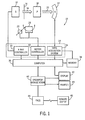
- Fig. 1 illustrates diagrammatically an imaging system 10 for acquiring and processing image data.
- system 10 is a computed tomography (CT) system designed both to acquire original image data, and to process the image data for display and analysis in accordance with the present technique.
- CT computed tomography
- imaging system 10 includes a source of X-ray radiation 12 positioned adjacent to a collimator 14.
- the source of X-ray radiation source 12 is typically an X-ray tube.
- Collimator 14 permits a stream of radiation 16 to pass into a region in which a subject, such as a human patient 18 is positioned. A portion of the radiation 20 passes through or around the subject and impacts a detector array, represented generally at reference numeral 22. Detector elements of the array produce electrical signals that represent the intensity of the incident X-ray beam. These signals are acquired and processed to reconstruct an image of the features within the subject.
- Source 12 is controlled by a system controller 24 which furnishes both power and control signals for CT examination sequences.
- detector 22 is coupled to the system controller 24, which commands acquisition of the signals generated in the detector 22.
- the system controller 24 may also execute various signal processing and filtration functions, such as for initial adjustment of dynamic ranges, interleaving of digital image data, and so forth.
- system controller 24 commands operation of the imaging system to execute examination protocols and to process acquired data.
- system controller 24 also includes signal processing circuitry, typically based upon a general purpose or application-specific digital computer, associated memory circuitry for storing programs and routines executed by the computer, as well as configuration parameters and image data, interface circuits, and so forth.
- system controller 24 is coupled to a rotational subsystem 26 and linear positioning subsystem 28.
- the rotational subsystem 26 enables the X-ray source 12, collimator 14 and the detector 22 to be rotated around the patient 18.
- the rotational subsystem 26 may include a gantry.
- the system controller 24 may be utilized to operate the gantry.
- the linear positioning subsystem 28 enables the patient 18, or more specifically a patient table, to be displaced linearly.
- the patient table may be linearly moved within the gantry to generate images of particular areas of the patient 18.
- the source of radiation may be controlled by an X-ray controller 30 disposed within the system controller 24.
- the X-ray controller 30 is configured to provide power and timing signals to the X-ray source 12.
- a motor controller 32 may be utilized to control the movement of the rotational subsystem 26 and the linear positioning subsystem 28.
- system controller 24 is also illustrated comprising a data acquisition system 34.
- the detector 22 is coupled to the system controller 24, and more particularly to the data acquisition system 34.
- the data acquisition system 34 receives data collected by readout electronics of the detector 22.
- the data acquisition system 34 typically receives sampled analog signals from the detector 22 and coverts the data to digital signals for subsequent processing by a computer 36.
- the computer 36 is typically coupled to the system controller 24.
- the data collected by the data acquisition system 34 may be transmitted to the computer 36 and moreover, to a memory 38. It should be understood that any type of memory to store a large amount of data may be utilized by such an exemplary system 10.
- the computer 36 is configured to receive commands and scanning parameters from an operator via an operator workstation 40 typically equipped with a keyboard and other input devices. An operator may control the system 10 via the input devices. Thus, the operator may observe the reconstructed image and other data relevant to the system from computer 36, initiate imaging, and so forth.
- a display 42 coupled to the operator workstation 40 may be utilized to observe the reconstructed image and to control imaging. Additionally, the scanned image may also be printed on to a printer 43 which may be coupled to the computer 36 and the operator workstation 40. Further, the operator workstation 40 may also be coupled to a picture archiving and communications system (PACS) 44. It should be noted that PACS 44 may be coupled to a remote system 46, radiology department information system (RIS), hospital information system (HIS) or to an internal or external network, so that others at different locations may gain access to the image and to the image data.
- RIS radiology department information system
- HIS hospital information system
- the computer 36 and operator workstation 46 may be coupled to other output devices which may include standard or special purpose computer monitors and associated processing circuitry.
- One or more operator workstations 40 may be further linked in the system for outputting system parameters, requesting examinations, viewing images, and so forth.
- displays, printers, workstations, and similar devices supplied within the system may be local to the data acquisition components, or may be remote from these components, such as elsewhere within an institution or hospital, or in an entirely different location, linked to the image acquisition system via one or more configurable networks, such as the Internet, virtual private networks, and so forth.
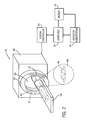
- an exemplary imaging system utilized in a present embodiment may be a CT scanning system 50.
- the CT scanning system 50 is illustrated with a frame 52 and a gantry 54 that has an aperture 56.
- the aperture 56 may typically be 60 cm to 70 cm in diameter.
- a patient table 58 is illustrated positioned in the aperture 56 of the frame 52 and the gantry 54.
- the patient table 58 is adapted so that a patient 18 may recline comfortably during the examination process.
- the patient table 58 is configured to be displaced linearly by the linear positioning subsystem 28 (see Fig. 1).
- the gantry 54 is illustrated with the source of radiation 12, typically an X-ray tube which emits X-ray radiation from a focal point 62.
- the stream of radiation is directed towards a particular region of the patient 18. It should be noted that the particular region of the patient 18 is typically chosen by an operator so that the most useful scan of a region may be imaged.
- X-ray source 12 projects an X-ray beam from the focal point 62 and toward detector array 22.
- the detector 22 is generally formed by a plurality of detector elements which sense the X-rays that pass through and around a subject of interest, such as particular body parts, for instance the liver, pancreas and so on. Each detector element produces an electrical signal that represents the intensity of the X-ray beam at the position of the element at the time the beam strikes the detector.
- the gantry 54 is rotated around the subject of interest so that a plurality of radiographic views may be collected by the computer 36.
- an image or slice is acquired which may incorporate, in certain modes, less or more than 360 degrees of projection, to formulate an image).
- the image is collimated to a desired thickness, typically between 0.5 mm and 10 mm using either lead shutters in front of the X-ray source 12 and different detector apertures 22.
- the collimator 14 typically defines the size and shape of the X-ray beam that emerges from the X-ray source 12.
- the detector 22 collects data of the attenuated X-ray beams. Data collected from the detector 22 then undergo pre-processing and calibration to condition the data to represent the line integrals of the attenuation coefficients of the scanned objects. The processed data, commonly called projections, are then filtered and backprojected to formulate an image of the scanned area.
- the computer 36 is typically used to control the entire CT system 10. The main computer that controls the operation of the system may be adapted to control features enabled by the system controller 24. Further, the operator workstation 40 is coupled to the computer 36 as well as to a display, so that the reconstructed image may be viewed.
- the image produced by the system of Figs. 1 and 2 reveals internal features of a patient.
- the image 64 may be displayed to show these features, such as indicated at reference numeral 66 in Fig. 2.
- a radiologist or physician would consider a hard copy of display of the image 64 to discern characteristic features of interest.
- Such features might include lesions, sizes and shapes of particular anatomies or organs, and other features which would be discernable in the image based upon the skill and knowledge of the individual practitioner.
- CAD algorithms may offer the potential for identifying, or at least localizing, certain features of interest, such as anatomical anomalies.
- the particular CAD algorithm is commonly selected based upon the type of feature to be identified, and upon the imaging modality used to create the image data.
- the CAD technique may employ segmentation algorithms, which identify the features of interest by reference to known or anticipated image characteristics, such as edges, identifiable structures, boundaries, changes or transitions in colors or intensities, changes or transitions in spectrographic information, and so forth.
- Current CAD algorithms generally offer the potential for identifying these features only. Subsequent processing and data acquisition is, then, entirely at the discretion and based upon the expertise of the practitioner.
- CAD algorithms may be considered as including several parts or modules, all of which may be implemented in the present technique.
- the CAD algorithm may include modules such as accessing image data, segmenting data or images, feature selection or extraction, classification, training, and visualization.
- the CAD processing may be performed on an acquisition projection data set prior to reconstruction, on two-dimensional reconstructed data (both in axial and scout modes), on three-dimensional reconstructed data (volume data or multiplanar reformats), or a suitable combination of such formats.
- the acquired projection data set may have a number of one-dimensional projections for two-dimensional scans or a number of two-dimensional projections for three-dimensional scans.
- segmentation, feature selection, classification prior to visualization may be performed.
- the data on which the CAD algorithm is implemented may be raw image acquisition system information, or may be partially or completely processed data.
- the data may originate from a tomographic data source, or may be diagnostic tomographic data (such as raw data in projection or Radon domain in CT imaging, single or multiple reconstructed two-dimensional images, or three-dimensional reconstructed volumetric image data).
- the segmentation portion of the CAD algorithm may identify a particular region of interest based upon calculated features in the tomographic data.
- the region of interest can be determined in a number of manners, using an entire data set or using part of a data set, such as a candidate mass region in a specific area.
- the particular segmentation technique may depend upon the anatomies to be identified, and may typically be based upon iterative thresholding, K-means segmentation, edge detection, edge linking, curve fitting, curve smoothing, two- and three-dimensional morphological filtering, region growing, fuzzy clustering, image/volume measurements, heuristics, knowledge-based rules, decision trees, neural networks, and so forth.
- the segmentation may be at least partially manual. Automated segmentation may also use prior knowledge such as shape and size of a mass to automatically delineate an area of interest.
- the feature extraction aspect of the CAD algorithm involves performing computations on the data which comprises the desired images.
- Multiple feature measures can be extracted from the image-based data using region of interest statistics, such as shape, size, density, and curvature.
- region of interest statistics such as shape, size, density, and curvature.
- features such as location, shape, or size of feature projections in a view or location may be used, such as to provide consistency between views.
- the classification aspects of the CAD algorithm may be, again, partially or fully manual or automated.
- the classification may be used to specifically identify regions of interest, such as by classification as normal or abnormal anatomies or lesions.
- Bayesian classifiers, neural networks, rule-based methods or fuzzy logic techniques, among others, can be used for classification.
- more than one CAD algorithm can be employed in parallel. Such parallel operation may involve performing CAD operations individually on portions of the image data, and combining the results of all CAD operations (logically by "and", "or” operations or both).
- CAD operations to detect multiple disease states or anatomical features of interest may be performed in series or in parallel.
- Prior to classification of masses for anatomies using the CAD algorithm prior knowledge from training may be incorporated.
- the training phase may involve the computation of several candidate features on known samples of normal and abnormal lesions or other features of interest.
- a feature selection algorithm may then be employed to sort through the candidate features and select only the useful ones and remove those that provide no information, or redundant information. This decision is based upon classification results with different combinations of candidate features.
- the feature selection algorithm may also be used to reduce the dimensionality for practical reasons of processing, storage and data transmission. Thus, optimal discrimination may be performed between features or anatomies identified by the CAD algorithm.
- the visualization aspect of the CAD algorithm permits reconstruction of useful images for review by human or machine observers.
- various types of images may be presented to the attending physician or to any other person needing such information, based upon any or all of the processing and modules performed by the CAD algorithm:
- the visualization may include two- or three-dimension renderings, superposition of markers, color or intensity variations, and so forth.
- the present technique offers the potential for further enhancing the automation offered by CAD techniques by enabling either further processing image data or further acquisition of image data.
- various parameters employed in post-processing of the acquired image data may be altered so as to render the reconstructed image more revealing or useful in identifying, localizing and diagnosing a physiological condition.
- such parameters may include contrast, spatial resolution (e.g. zoom), color, and so forth.
- the post-processing based upon the results of initial CAD evaluation may include mathematical evaluations such as segmentation, registration, computation of areas or volumes, and so forth.
- the "post-processing" may also involve the use of different reconstruction algorithms or different reconstruction parameters to generate images.
- filter kernels Soft, Standard, Detail, Bone, Edge, Lung, etc.
- Different filter kernels enhance different desired features in the image.
- Other reconstruction parameters such as reconstruction field-of-view, matrix size, targeting locations, etc. can also be modified to produce additional images based on the initial CAD results.
- the initial CAD evaluation may also enable the automatic acquisition of subsequent images so as to enable a complete useful set of information to be gathered during a single patient session.
- the subsequent processing may be in order due, for example, to particular features which appear in images initially acquired but are not adequately shown.
- the subsequent acquisition may include acquisition of data from other regions of the patient's body, at different orientations with respect to tissues of interest, at different resolution levels, and so forth.
- entirely different acquired data may be desired based upon the initial CAD evaluation, such as data acquired via an entirely different modality system.
- Fig. 3 represents a flow chart of exemplary steps in carrying out a processing routine based upon CAD analysis.
- the technique summarized in Fig. 3 begins at step 68 where initial data acquisition is performed.
- this data acquisition may be based upon any suitable imaging modality, typically selected in accordance with the particular anatomy to the imaged and the analysis to be performed.
- imaging modality typically selected in accordance with the particular anatomy to the imaged and the analysis to be performed.
- the modality may be coupled with particular settings, also typically dictated by the physics of the system, to provide higher or lower contrast images, volume rendering, sensitivity or insensitivity to specific tissues or components, and so forth.
- the image acquisition may be coupled with the use of contrast agents or other markers used to target or highlight particular features or areas of interest.
- the image data acquisition of step 68 is typically initiated by an operator interfacing with the system via the operator workstation 40 (see Fig. 2).
- Readout electronics detect signals generated by virtue of the impact radiation on the scanner detector, and the system processes these signals to produce useful image data.
- the initial image is formed.
- the formation of the image at step 70 may include reconstruction and display of the image, or simply processing of the image data.
- a reconstructed image may be useful by a physician or operator of the system to guide in the subsequent processing or image data acquisition steps. In other situations, it may be desirable to actually reconstruct and display the image, but the image data is nevertheless analyzed as described below.
- Step 70 will also typically include storage of the image data for subsequent processing.
- a CAD algorithm is carried out on the acquired image data.
- the CAD algorithm will typically be selected in accordance with the imaging modality and with the particular data type and anatomy represented in the image.
- the CAD analysis may identify various features of interest, including disease states, lesions, or any other physiological feature of interest.
- a target region is selected as summarized in step 74 in Fig. 3.
- the target region may be larger or smaller than a similar region of the initial image, or may be of a different or adjacent region.
- the target region selected at step 74 may provide for greater spatial resolution (e.g. zoom-in) of a potential lesion.
- the target region is preferably selected automatically based upon the output of the CAD analysis performed at step 72. Where, for example, the CAD analysis indicates that subsequent processing may reveal additional details in an image, a target region corresponding to the location of such details will be selected at step 74.
- additional processing may be in order as summarized at step 76 in Fig. 3.
- Such additional processing may include enhancement of certain features in the image, contrast of certain features, edge or structure detection, reprocessing of spatial resolutions (e.g. zooming in or zooming out), or any other suitable processing steps that may be performed upon the acquired image data.
- the additional processing at step 76 may also include automatic segmentation, calculation of sizes or volumes of features of interest, and so forth.
- the additional processing at step 76 may also include automatic selection of optimal parameters used in the reconstruction and produce additional images based on the optimal parameters. If such additional processing is desired, the processing is performed and a subsequent or additional image data set may be generated as indicated at step 78.
- This image data set may be stored separately for display or review.
- the image data set will differ from the original processed data by the subsequent processing programmed at step 76.
- the procedure advances to step 80 where some or all of the reconstructed images may be presented to physicians or radiologists.
- initial images may be reconstructed and the CAD algorithm applied to the image data as described herein, the analysis may be partially or fully performed without such initial visualization.
- some or all of the CAD algorithm analysis may take place in Radon space.
- Ultimate useful image reconstruction may include visualizations of initial images, enhanced images, or both.
- the results of the CAD analysis may, where desired, even guide the type of image reconstruction performed, such as from Radon space in the CT imaging example.
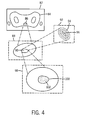
- Fig. 4 An initial image 82 is acquired that illustrates features 84 potentially of interest.
- the features may include specific regions or targets 86 of interest.
- Subsequent processing then, may be performed as summarized above to render a subsequent image 88 in which the target 86 is reprocessed, such as for more detailed or analytical rendering. Even within such regions, additional processing may be performed through similar steps to gain additional information on the features of interest.
- a particular feature 90 is reprocessed, such as through segmentation, to render a subsequent image 92 in which limits 94 of a core object 96 are identified.
- Additional further processing may be performed, such as indicated at reference numeral 98, to render additional images or image data, such as to further increase spatial resolution of a region 100 containing a feature 102 of interest.
- various processing steps based upon sequential CAD analysis may be different from one another.
- several different types of post-processing of the image data may be performed. Again, these processes are prescribed as a result of the CAD analysis performed on the acquired image data.
- Fig. 5 summarizes exemplary steps in a process in which additional post-processing and/or further data acquisition may be performed.
- the method of Fig. 5 begin at step 104 where a computer aided processing and acquisition algorithm (CAPA) requests information from a desired imaging modality.
- CAA computer aided processing and acquisition algorithm
- the algorithm may be initiated so as to prescribe a CT scan of a particular anatomy of interest.
- the CAPA processing denoted generally by reference numeral 106 then begins.
- step 104 may include all of the steps summarized above with reference to Fig. 3.
- an imaging system modality A such as a CT imaging system
- a different modality system may be called into play and employed for the subsequent image data acquisition summarized in Fig. 5.
- Fig. 5 may also be considered to summarize a more general case in which the subsequent image data acquisition sequence is carried out on an imaging system of the same general modality, but with different settings. That is, the process 106 may be performed on the same general type of imaging system, or even the same imaging system, with different settings as determined desirable as a result of the initial CAD analysis.
- a image data may be acquired from an X-ray system and the image data analyzed to identify a feature of potential interest. Images may be reconstructed based on the X-ray image data. Subsequent image acquisition may then be ordered via a CT system to provide a better view of the particular identified feature. One or more images may then be reconstructed based on the CT image data. As noted above, the actual image reconstruction based on the initial data may be optional, or at least distinct from the analysis performed by the CAD algorithm and the subsequent acquisition of the second image data.
- the subsequent data acquisition begins at step 108 where new initial data is acquired.
- this data acquisition will depend upon the nature of the modality B system, the parameter settings desired to image the features of interest, as well as other parameters dictated by the tissue and the like.
- the image is formed from the acquired data which may be reconstructed for display or simply stored and analyzed.
- a CAD routine is performed on the newly-acquired image data. Again, the CAD routine executed at step 112 will typically be specific to the modality B, its settings, and the features to be imaged or identified.
- a preliminary target is identified, similar to the identification of a target region at step 74 summarized above with reference to Fig. 3.
- the result from this step may be compared against the initial CAD result to provide complementary information.
- the process may continue with further CAD analysis of the subsequent image, as noted above with respect to Fig. 4.
- step 116 even further image data acquisition may be performed as summarized at decision block 120. If such additional data acquisition is in order, this can be performed as indicated at step 122, and the entire process may return to step 108 or step 112 for even further image data acquisition and analysis. If the image data acquisition and analysis on modality B is terminated, images may be reconstructed and presented to attending physicians, clinicians, or radiologist as summarized at step 124. Also in accordance with the more general case of Fig. 5, additional data acquisition prescribed at step 122 may be performed on the same or even further modality systems, such as a modality C as indicated at step 126.
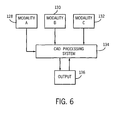
- Fig. 6 The system and inter-system scheme enabled by the processing summarized in Fig. 5 is illustrated diagrammatically in Fig. 6.
- several modality systems 128, 130 and 132 may be used to acquire and process image data.
- the modality systems may be similar to one another or may be entirely different and distinct, based upon their own specific physics and imaging principles.
- the modalities may include such systems as CT imaging systems, MRI systems, PET systems, ultrasound systems, nuclear medicine systems, and so forth.
- Input from a first modality is then used as a basis for CAD analysis in a CAD processing system represented generally at reference numeral 134 in Fig. 6.
- the CAD processing system may be an integral part of the modality imaging system, or may be separate and distinct, even remote from the imaging system. Based upon the CAD analysis performed by this system, subsequent processing may be performed on the same image data set, or additional image data may be acquired from the same modality or from other modality systems which are more suited to imaging or analysis of the features of interest. Results of the CAD analysis and imaging sequences may be displayed or summarized via various output devices 136, such as screen displays, printers, photographic reproduction equipment, and so forth.
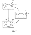
- FIG. 7 This overall system structure enables a great variety of image acquisition, processing and analysis techniques to be implemented as summarized generally in Fig. 7.
- an initial image 138 is acquired and analyzed including features of interest 140.
- subsequent images 142 and 146 may be acquired and analyzed to show the features of interest 144 and 148, either presented in a similar manner or in an entirely different manner, depending upon the processing, image acquisition, and analysis and display desired.
Abstract

Description
- The present invention relates generally to imaging procedures. Particularly, the present invention relates to a method for improving computer aided detection or diagnosis by utilizing a computer aided processing technique.
- Computer aided diagnosis (CAD), such as screening mammography and evaluation of other disease states or medical or physiological events, is typically based upon various types of analysis of a series of collected images. The collected images are analyzed by utilizing the pathologies that are highlighted by a CAD algorithm. The results are generally viewed by radiologists for final diagnosis. As can be appreciated by those skilled in the art, certain subsequent imaging procedures may become feasible or may be recognized as desirable due to the improved management of data volume.
- It should be noted that computer aided CAD may be utilized in any imaging modality, such as computed tomography (CT), magnetic resonance imaging (MRI), X-ray systems, ultrasound systems, positron emission tomography (PET), and so forth. CAD algorithms in certain of these modalities may provide advantages over those in other modalities, depending upon the imaging capabilities of the modality, the tissue being imaged, and so forth. Computed tomography, for example, is generally a diagnostic procedure in which cross-sectional images or slices are made by an X-ray system. The CT scanning procedure combines the use of a computer system and a rotating X-ray device to create detailed cross sectional images or "slices" of a patient's organs and other body parts. The imaging capabilities are physically similar to those of X-ray systems. MRI, ultrasound, PET, and other modalities similarly are adapted to imaging certain tissues or anatomies, and provide advantages for the different CAD algorithm employed with images they produce.
- Each imaging modality is based upon unique physics and image processing techniques. For example, a CT system measures the attenuation of X-ray beams passed through a patient from numerous angles, and then, based upon these measurements, a computer is able to reconstruct images of the portions of a patient's body responsible for the radiation attenuation. As will be appreciated by those skilled in the art, these images are based upon separate examination of a series of continuous cross sections. Thus, a virtual 3-D image may be produced by a CT examination. It should be pointed out that a CT system does not actually directly provide an image, but rather numerical values of tissue density. The image based upon the reconstructed data is typically displayed on a cathode ray tube, and may be printed or reproduced on film.
- Continuing with the example of CT imaging, CT scanners operate by projecting fan shaped X-ray beams from an X-ray source that is collimated and passes through the object, such as a patient, that is then detected by a detector element. The data is then used to produce a useful image. Thus, the detector element produces data based on the attenuation of the X-ray beams, and the data are processed by computer analysis. The locations of pathologies may then be highlighted by the CAD algorithm, and thus brought to a human observer's attention. The results may then be reviewed by a radiologist or other physician for final diagnosis.
- Each imaging modality may provide unique advantages over other modalities for certain types of disease or physiological condition detection. For example, CT scanning provides advantages over other types of techniques in diagnosing disease particularly because it illustrates the shape and exact location of organs, soft tissues, and bones any slice of the body. Further, CT scans may help doctors distinguish between a simple cyst, for example, and a solid tumor, and thus evaluate abnormalities more accurately. As mentioned above, other imaging modalities are similarly best suited to imaging other physiological features of interest, and to corresponding CAD algorithms.
- Existing techniques for computerized diagnosis of physiological features suffer from certain serious drawbacks. For example, the output of the CAD analysis is generally fairly interactive, requiring assessment and evaluation by a seasoned practitioner. Due to time constraints and the availability of such persons, a patient is often called upon to report for certain types of examination, with further examinations needing to be scheduled, when appropriate, based upon the review of the CAD analysis. That is to say, patients often must return for additional tests on the same or a different modality imaging system in order to properly evaluate and diagnose potential conditions. The resulting procedure is not only time-consuming for the patient and for the physician, but ultimately results in the entire process extending over a considerable period of time. Additional appointments for subsequent imaging can also result in considerable expense both for the patient, for hospitals and clinics, and for insurance carriers. There is a need, therefore, for improved technique for guiding subsequent image data acquisition based upon analysis by a CAD algorithm. There is a particular need for a technique which would allow additional data to be prescribed and acquired both from the same or from the same type of imaging system as used in initial evaluations, and from other modality systems, where appropriate.
- The present technique provides an improved method for useful medical images for diagnosing patients that responds to such needs. The technique makes use of initial CAD information to guide additional data acquisition with or without additional human operator assistance. Thus, once a feature of interest is identified by the CAD algorithm a computer may automatically direct the imaging system to re-acquire additional images at the suspected location, or may instruct or suggest that an operator do so.
- In accordance with one embodiment of the invention, a method is provided for processing an image generated by an imaging system. The method includes acquiring a first series of images from a first imaging system. The first series of images is then processed in accordance with a CAD algorithm. A second series of images is then acquired based upon the results of the CAD algorithm.
- In accordance with another aspect of the invention, an imaging system includes a first image data acquisition system configured to acquire medical images, and a computer system. The computer system is coupled to the image data acquisition system and is configured to generate a first series of images from image data acquired by the acquisition system. The computer system is further configured to process the first series of images via a CAD algorithm. The computer system is configured, as well, to prescribe acquisition of a second series of images based upon results of the CAD algorithm.
- The invention will now be described in greater detail, by way of example, with reference to the drawings, in which:-
- Fig. 1 is a diagrammatical view of an exemplary imaging system in the form of a CT imaging system for use in producing processed images in accordance with aspects of the present technique;
- Fig. 2 is another diagrammatical view of a physical implementation of the CT system of Fig. 1;
- Fig. 3 is a flow chart illustrating exemplary steps in logic for carrying out subsequent image data processing based upon CAD analysis of acquired image data;
- Fig. 4 is a diagrammatical representation of a series of processed images resulting from post-processing based upon CAD analysis;
- Fig. 5 is a flow chart illustrating exemplary steps in logic for acquiring and processing subsequent image data, including data from different modality imaging systems, based upon results of CAD analysis;
- Fig. 6 is a diagrammatical representation of certain functional components of a CAD-based image data acquisition and processing scheme; and
- Fig. 7 is a diagrammatical representation of a series of processed images acquired in succession based upon results of CAD analysis of initial image data.
-
- Fig. 1 illustrates diagrammatically an
imaging system 10 for acquiring and processing image data. In the illustrated embodiment,system 10 is a computed tomography (CT) system designed both to acquire original image data, and to process the image data for display and analysis in accordance with the present technique. In the embodiment illustrated in Fig. 1,imaging system 10 includes a source ofX-ray radiation 12 positioned adjacent to acollimator 14. In this exemplary embodiment, the source ofX-ray radiation source 12 is typically an X-ray tube. -
Collimator 14 permits a stream ofradiation 16 to pass into a region in which a subject, such as ahuman patient 18 is positioned. A portion of theradiation 20 passes through or around the subject and impacts a detector array, represented generally atreference numeral 22. Detector elements of the array produce electrical signals that represent the intensity of the incident X-ray beam. These signals are acquired and processed to reconstruct an image of the features within the subject. -
Source 12 is controlled by asystem controller 24 which furnishes both power and control signals for CT examination sequences. Moreover,detector 22 is coupled to thesystem controller 24, which commands acquisition of the signals generated in thedetector 22. Thesystem controller 24 may also execute various signal processing and filtration functions, such as for initial adjustment of dynamic ranges, interleaving of digital image data, and so forth. In general,system controller 24 commands operation of the imaging system to execute examination protocols and to process acquired data. In the present context,system controller 24 also includes signal processing circuitry, typically based upon a general purpose or application-specific digital computer, associated memory circuitry for storing programs and routines executed by the computer, as well as configuration parameters and image data, interface circuits, and so forth. - In the embodiment illustrated in Fig. 1,
system controller 24 is coupled to arotational subsystem 26 andlinear positioning subsystem 28. Therotational subsystem 26 enables theX-ray source 12,collimator 14 and thedetector 22 to be rotated around thepatient 18. It should be noted that therotational subsystem 26 may include a gantry. Thus, thesystem controller 24 may be utilized to operate the gantry. Thelinear positioning subsystem 28 enables thepatient 18, or more specifically a patient table, to be displaced linearly. Thus, the patient table may be linearly moved within the gantry to generate images of particular areas of thepatient 18. - Additionally, as will be appreciated by those skilled in the art, the source of radiation may be controlled by an
X-ray controller 30 disposed within thesystem controller 24. Particularly, theX-ray controller 30 is configured to provide power and timing signals to theX-ray source 12. Amotor controller 32 may be utilized to control the movement of therotational subsystem 26 and thelinear positioning subsystem 28. - Further, the
system controller 24 is also illustrated comprising a data acquisition system 34. In this exemplary embodiment, thedetector 22 is coupled to thesystem controller 24, and more particularly to the data acquisition system 34. The data acquisition system 34 receives data collected by readout electronics of thedetector 22. The data acquisition system 34 typically receives sampled analog signals from thedetector 22 and coverts the data to digital signals for subsequent processing by acomputer 36. - The
computer 36 is typically coupled to thesystem controller 24. The data collected by the data acquisition system 34 may be transmitted to thecomputer 36 and moreover, to amemory 38. It should be understood that any type of memory to store a large amount of data may be utilized by such anexemplary system 10. Also thecomputer 36 is configured to receive commands and scanning parameters from an operator via anoperator workstation 40 typically equipped with a keyboard and other input devices. An operator may control thesystem 10 via the input devices. Thus, the operator may observe the reconstructed image and other data relevant to the system fromcomputer 36, initiate imaging, and so forth. - A
display 42 coupled to theoperator workstation 40 may be utilized to observe the reconstructed image and to control imaging. Additionally, the scanned image may also be printed on to aprinter 43 which may be coupled to thecomputer 36 and theoperator workstation 40. Further, theoperator workstation 40 may also be coupled to a picture archiving and communications system (PACS) 44. It should be noted thatPACS 44 may be coupled to aremote system 46, radiology department information system (RIS), hospital information system (HIS) or to an internal or external network, so that others at different locations may gain access to the image and to the image data. - It should be further noted that the
computer 36 andoperator workstation 46 may be coupled to other output devices which may include standard or special purpose computer monitors and associated processing circuitry. One ormore operator workstations 40 may be further linked in the system for outputting system parameters, requesting examinations, viewing images, and so forth. In general, displays, printers, workstations, and similar devices supplied within the system may be local to the data acquisition components, or may be remote from these components, such as elsewhere within an institution or hospital, or in an entirely different location, linked to the image acquisition system via one or more configurable networks, such as the Internet, virtual private networks, and so forth. - Referring generally to Fig. 2, an exemplary imaging system utilized in a present embodiment may be a
CT scanning system 50. TheCT scanning system 50 is illustrated with aframe 52 and agantry 54 that has anaperture 56. Theaperture 56 may typically be 60 cm to 70 cm in diameter. Further, a patient table 58 is illustrated positioned in theaperture 56 of theframe 52 and thegantry 54. The patient table 58 is adapted so that a patient 18 may recline comfortably during the examination process. Additionally, the patient table 58 is configured to be displaced linearly by the linear positioning subsystem 28 (see Fig. 1). Thegantry 54 is illustrated with the source ofradiation 12, typically an X-ray tube which emits X-ray radiation from afocal point 62. The stream of radiation is directed towards a particular region of thepatient 18. It should be noted that the particular region of thepatient 18 is typically chosen by an operator so that the most useful scan of a region may be imaged. - In typical operation, X-ray
source 12 projects an X-ray beam from thefocal point 62 and towarddetector array 22. Thedetector 22 is generally formed by a plurality of detector elements which sense the X-rays that pass through and around a subject of interest, such as particular body parts, for instance the liver, pancreas and so on. Each detector element produces an electrical signal that represents the intensity of the X-ray beam at the position of the element at the time the beam strikes the detector. Furthermore, thegantry 54 is rotated around the subject of interest so that a plurality of radiographic views may be collected by thecomputer 36. Thus, an image or slice is acquired which may incorporate, in certain modes, less or more than 360 degrees of projection, to formulate an image). The image is collimated to a desired thickness, typically between 0.5 mm and 10 mm using either lead shutters in front of theX-ray source 12 anddifferent detector apertures 22. The collimator 14 (see Fig. 1) typically defines the size and shape of the X-ray beam that emerges from theX-ray source 12. - Thus, as the
X-ray source 12 and thedetector 22 rotate, thedetector 22 collects data of the attenuated X-ray beams. Data collected from thedetector 22 then undergo pre-processing and calibration to condition the data to represent the line integrals of the attenuation coefficients of the scanned objects. The processed data, commonly called projections, are then filtered and backprojected to formulate an image of the scanned area. As mentioned above, thecomputer 36 is typically used to control theentire CT system 10. The main computer that controls the operation of the system may be adapted to control features enabled by thesystem controller 24. Further, theoperator workstation 40 is coupled to thecomputer 36 as well as to a display, so that the reconstructed image may be viewed. - Once reconstructed, the image produced by the system of Figs. 1 and 2 reveals internal features of a patient. As illustrated generally in Fig. 2, the image 64 may be displayed to show these features, such as indicated at
reference numeral 66 in Fig. 2. In traditional approaches to diagnosis of medical conditions, such as disease states, and more generally of medical events, a radiologist or physician would consider a hard copy of display of the image 64 to discern characteristic features of interest. Such features might include lesions, sizes and shapes of particular anatomies or organs, and other features which would be discernable in the image based upon the skill and knowledge of the individual practitioner. - The present technique implements certain of these capabilities by CAD algorithms. As will be appreciated by those skilled in the art, CAD algorithms may offer the potential for identifying, or at least localizing, certain features of interest, such as anatomical anomalies. The particular CAD algorithm is commonly selected based upon the type of feature to be identified, and upon the imaging modality used to create the image data. The CAD technique may employ segmentation algorithms, which identify the features of interest by reference to known or anticipated image characteristics, such as edges, identifiable structures, boundaries, changes or transitions in colors or intensities, changes or transitions in spectrographic information, and so forth. Current CAD algorithms generally offer the potential for identifying these features only. Subsequent processing and data acquisition is, then, entirely at the discretion and based upon the expertise of the practitioner.
- CAD algorithms may be considered as including several parts or modules, all of which may be implemented in the present technique. In general, the CAD algorithm may include modules such as accessing image data, segmenting data or images, feature selection or extraction, classification, training, and visualization. Moreover, the CAD processing may be performed on an acquisition projection data set prior to reconstruction, on two-dimensional reconstructed data (both in axial and scout modes), on three-dimensional reconstructed data (volume data or multiplanar reformats), or a suitable combination of such formats. The acquired projection data set may have a number of one-dimensional projections for two-dimensional scans or a number of two-dimensional projections for three-dimensional scans. Using the acquired or reconstructed data, segmentation, feature selection, classification prior to visualization may be performed. These basic processes can be done in parallel, or in various combinations.
- The data on which the CAD algorithm is implemented may be raw image acquisition system information, or may be partially or completely processed data. The data may originate from a tomographic data source, or may be diagnostic tomographic data (such as raw data in projection or Radon domain in CT imaging, single or multiple reconstructed two-dimensional images, or three-dimensional reconstructed volumetric image data).
- The segmentation portion of the CAD algorithm may identify a particular region of interest based upon calculated features in the tomographic data. The region of interest can be determined in a number of manners, using an entire data set or using part of a data set, such as a candidate mass region in a specific area. The particular segmentation technique may depend upon the anatomies to be identified, and may typically be based upon iterative thresholding, K-means segmentation, edge detection, edge linking, curve fitting, curve smoothing, two- and three-dimensional morphological filtering, region growing, fuzzy clustering, image/volume measurements, heuristics, knowledge-based rules, decision trees, neural networks, and so forth. Alternatively, the segmentation may be at least partially manual. Automated segmentation may also use prior knowledge such as shape and size of a mass to automatically delineate an area of interest.
- The feature extraction aspect of the CAD algorithm involves performing computations on the data which comprises the desired images. Multiple feature measures can be extracted from the image-based data using region of interest statistics, such as shape, size, density, and curvature. For projection space data, features such as location, shape, or size of feature projections in a view or location may be used, such as to provide consistency between views.
- The classification aspects of the CAD algorithm may be, again, partially or fully manual or automated. In particular, the classification may be used to specifically identify regions of interest, such as by classification as normal or abnormal anatomies or lesions. Bayesian classifiers, neural networks, rule-based methods or fuzzy logic techniques, among others, can be used for classification. It should be noted that more than one CAD algorithm can be employed in parallel. Such parallel operation may involve performing CAD operations individually on portions of the image data, and combining the results of all CAD operations (logically by "and", "or" operations or both). In addition, CAD operations to detect multiple disease states or anatomical features of interest may be performed in series or in parallel.
- Prior to classification of masses for anatomies using the CAD algorithm, prior knowledge from training may be incorporated. The training phase may involve the computation of several candidate features on known samples of normal and abnormal lesions or other features of interest. A feature selection algorithm may then be employed to sort through the candidate features and select only the useful ones and remove those that provide no information, or redundant information. This decision is based upon classification results with different combinations of candidate features. The feature selection algorithm may also be used to reduce the dimensionality for practical reasons of processing, storage and data transmission. Thus, optimal discrimination may be performed between features or anatomies identified by the CAD algorithm.
- The visualization aspect of the CAD algorithm permits reconstruction of useful images for review by human or machine observers. Thus, various types of images may be presented to the attending physician or to any other person needing such information, based upon any or all of the processing and modules performed by the CAD algorithm: The visualization may include two- or three-dimension renderings, superposition of markers, color or intensity variations, and so forth.
- The present technique offers the potential for further enhancing the automation offered by CAD techniques by enabling either further processing image data or further acquisition of image data. In the case of processing, various parameters employed in post-processing of the acquired image data may be altered so as to render the reconstructed image more revealing or useful in identifying, localizing and diagnosing a physiological condition. In particular, such parameters may include contrast, spatial resolution (e.g. zoom), color, and so forth. Moreover, the post-processing based upon the results of initial CAD evaluation may include mathematical evaluations such as segmentation, registration, computation of areas or volumes, and so forth. The "post-processing" may also involve the use of different reconstruction algorithms or different reconstruction parameters to generate images. For example, based on initial CAD results, different filter kernels (Soft, Standard, Detail, Bone, Edge, Lung, etc.) may be used to produce additional images from the original scan. Different filter kernels enhance different desired features in the image. Other reconstruction parameters, such as reconstruction field-of-view, matrix size, targeting locations, etc. can also be modified to produce additional images based on the initial CAD results.
- The initial CAD evaluation may also enable the automatic acquisition of subsequent images so as to enable a complete useful set of information to be gathered during a single patient session. The subsequent processing may be in order due, for example, to particular features which appear in images initially acquired but are not adequately shown. Thus, the subsequent acquisition may include acquisition of data from other regions of the patient's body, at different orientations with respect to tissues of interest, at different resolution levels, and so forth. Moreover, entirely different acquired data may be desired based upon the initial CAD evaluation, such as data acquired via an entirely different modality system.
- Fig. 3 represents a flow chart of exemplary steps in carrying out a processing routine based upon CAD analysis. The technique summarized in Fig. 3 begins at
step 68 where initial data acquisition is performed. As noted above, this data acquisition may be based upon any suitable imaging modality, typically selected in accordance with the particular anatomy to the imaged and the analysis to be performed. By way of example, those skilled in the art will recognize that the physical limitation of certain imaging modalities render them more suitable for imaging soft tissues as opposed to bone or other more dense tissue or objects. Moreover, the modality may be coupled with particular settings, also typically dictated by the physics of the system, to provide higher or lower contrast images, volume rendering, sensitivity or insensitivity to specific tissues or components, and so forth. Finally, the image acquisition may be coupled with the use of contrast agents or other markers used to target or highlight particular features or areas of interest. In a CT system, for example, the image data acquisition ofstep 68 is typically initiated by an operator interfacing with the system via the operator workstation 40 (see Fig. 2). Readout electronics detect signals generated by virtue of the impact radiation on the scanner detector, and the system processes these signals to produce useful image data. - At
step 70 of Fig. 3, the initial image is formed. The formation of the image atstep 70 may include reconstruction and display of the image, or simply processing of the image data. In general, a reconstructed image may be useful by a physician or operator of the system to guide in the subsequent processing or image data acquisition steps. In other situations, it may be desirable to actually reconstruct and display the image, but the image data is nevertheless analyzed as described below.Step 70 will also typically include storage of the image data for subsequent processing. - At
step 72, a CAD algorithm is carried out on the acquired image data. As noted above, the CAD algorithm will typically be selected in accordance with the imaging modality and with the particular data type and anatomy represented in the image. The CAD analysis may identify various features of interest, including disease states, lesions, or any other physiological feature of interest. Based upon the analysis, a target region is selected as summarized instep 74 in Fig. 3. The target region may be larger or smaller than a similar region of the initial image, or may be of a different or adjacent region. By way or example, the target region selected atstep 74 may provide for greater spatial resolution (e.g. zoom-in) of a potential lesion. The target region is preferably selected automatically based upon the output of the CAD analysis performed atstep 72. Where, for example, the CAD analysis indicates that subsequent processing may reveal additional details in an image, a target region corresponding to the location of such details will be selected atstep 74. - Based upon the target selection of
step 74 and upon the CAD analysis performed atstep 72, additional processing may be in order as summarized atstep 76 in Fig. 3. Such additional processing may include enhancement of certain features in the image, contrast of certain features, edge or structure detection, reprocessing of spatial resolutions (e.g. zooming in or zooming out), or any other suitable processing steps that may be performed upon the acquired image data. The additional processing atstep 76 may also include automatic segmentation, calculation of sizes or volumes of features of interest, and so forth. The additional processing atstep 76 may also include automatic selection of optimal parameters used in the reconstruction and produce additional images based on the optimal parameters. If such additional processing is desired, the processing is performed and a subsequent or additional image data set may be generated as indicated atstep 78. This image data set may be stored separately for display or review. The image data set will differ from the original processed data by the subsequent processing programmed atstep 76. Following a generation of the additional image atstep 78, or if no additional processing is in order atstep 76, the procedure advances to step 80 where some or all of the reconstructed images may be presented to physicians or radiologists. - It should be noted that, as mentioned above, while initial images may be reconstructed and the CAD algorithm applied to the image data as described herein, the analysis may be partially or fully performed without such initial visualization. Thus, in case of CT image data, some or all of the CAD algorithm analysis may take place in Radon space. Ultimate useful image reconstruction may include visualizations of initial images, enhanced images, or both. The results of the CAD analysis may, where desired, even guide the type of image reconstruction performed, such as from Radon space in the CT imaging example.
- The foregoing process is summarized diagrammatically in Fig. 4. As shown in Fig. 4, an
initial image 82 is acquired that illustrates features 84 potentially of interest. In particular, the features may include specific regions or targets 86 of interest. Subsequent processing, then, may be performed as summarized above to render asubsequent image 88 in which thetarget 86 is reprocessed, such as for more detailed or analytical rendering. Even within such regions, additional processing may be performed through similar steps to gain additional information on the features of interest. By way of example, in the diagram of Fig. 4, aparticular feature 90 is reprocessed, such as through segmentation, to render asubsequent image 92 in which limits 94 of acore object 96 are identified. Additional further processing may be performed, such as indicated atreference numeral 98, to render additional images or image data, such as to further increase spatial resolution of aregion 100 containing afeature 102 of interest. It should be noted that the various processing steps based upon sequential CAD analysis may be different from one another. Thus, through the series ofimages - As noted above, the present technique allows for both processing and acquisition of image data based upon CAD analysis. Fig. 5 summarizes exemplary steps in a process in which additional post-processing and/or further data acquisition may be performed. The method of Fig. 5 begin at
step 104 where a computer aided processing and acquisition algorithm (CAPA) requests information from a desired imaging modality. In the foregoing example of a CT system, for example, the algorithm may be initiated so as to prescribe a CT scan of a particular anatomy of interest. The CAPA processing, denoted generally byreference numeral 106 then begins. It should be noted thatstep 104 may include all of the steps summarized above with reference to Fig. 3. That is, an imaging system modality A, such as a CT imaging system, may be used to acquire information, perform initial CAD analysis, reprocess or analyze the image data, and so forth. Where subsequent data acquisition appears to be in order, such as due to the particular anatomy of interest, the imaging capabilities and limitations of the modality system used to acquire the initial information, and so forth, a different modality system may be called into play and employed for the subsequent image data acquisition summarized in Fig. 5. It should also be noted that, as a general matter, Fig. 5 may also be considered to summarize a more general case in which the subsequent image data acquisition sequence is carried out on an imaging system of the same general modality, but with different settings. That is, theprocess 106 may be performed on the same general type of imaging system, or even the same imaging system, with different settings as determined desirable as a result of the initial CAD analysis. - By way of example, a image data may be acquired from an X-ray system and the image data analyzed to identify a feature of potential interest. Images may be reconstructed based on the X-ray image data. Subsequent image acquisition may then be ordered via a CT system to provide a better view of the particular identified feature. One or more images may then be reconstructed based on the CT image data. As noted above, the actual image reconstruction based on the initial data may be optional, or at least distinct from the analysis performed by the CAD algorithm and the subsequent acquisition of the second image data.
- This procedure is illustrated generally in Fig. 5. As summarized in Fig. 5, the subsequent data acquisition begins at
step 108 where new initial data is acquired. As noted above, this data acquisition will depend upon the nature of the modality B system, the parameter settings desired to image the features of interest, as well as other parameters dictated by the tissue and the like. Atstep 110 the image is formed from the acquired data which may be reconstructed for display or simply stored and analyzed. At step 112 a CAD routine is performed on the newly-acquired image data. Again, the CAD routine executed atstep 112 will typically be specific to the modality B, its settings, and the features to be imaged or identified. At step 114 a preliminary target is identified, similar to the identification of a target region atstep 74 summarized above with reference to Fig. 3. The result from this step may be compared against the initial CAD result to provide complementary information. Atstep 116 it is determined whether additional processing is desired, and if so, an additional subsequent image data sets are generated based upon such processing as indicated atstep 118. The process may continue with further CAD analysis of the subsequent image, as noted above with respect to Fig. 4. - To complete the general case summarized in Fig. 5, following the additional processing, if any, resulting at
step 116, even further image data acquisition may be performed as summarized atdecision block 120. If such additional data acquisition is in order, this can be performed as indicated atstep 122, and the entire process may return to step 108 or step 112 for even further image data acquisition and analysis. If the image data acquisition and analysis on modality B is terminated, images may be reconstructed and presented to attending physicians, clinicians, or radiologist as summarized atstep 124. Also in accordance with the more general case of Fig. 5, additional data acquisition prescribed atstep 122 may be performed on the same or even further modality systems, such as a modality C as indicated atstep 126. - The system and inter-system scheme enabled by the processing summarized in Fig. 5 is illustrated diagrammatically in Fig. 6. As shown at Fig. 6,
several modality systems reference numeral 134 in Fig. 6. The CAD processing system may be an integral part of the modality imaging system, or may be separate and distinct, even remote from the imaging system. Based upon the CAD analysis performed by this system, subsequent processing may be performed on the same image data set, or additional image data may be acquired from the same modality or from other modality systems which are more suited to imaging or analysis of the features of interest. Results of the CAD analysis and imaging sequences may be displayed or summarized viavarious output devices 136, such as screen displays, printers, photographic reproduction equipment, and so forth. - This overall system structure enables a great variety of image acquisition, processing and analysis techniques to be implemented as summarized generally in Fig. 7. In the representation of Fig. 7, an
initial image 138 is acquired and analyzed including features ofinterest 140. Where the image, however, would complimented by image data acquired through different system settings or through a different modality system,subsequent images interest 144 and 148, either presented in a similar manner or in an entirely different manner, depending upon the processing, image acquisition, and analysis and display desired. - For the sake of good order, various aspects of the invention are set out in the following clauses:-
- 1. A method for acquiring an image on an imaging system comprising the
acts of:
- (a) accessing at least first image data from a first imaging system;
- (b) processing the first image data in accordance with a CAD algorithm; and
- (c) acquiring at least second image data based upon results of the CAD algorithm.
- 2. The method of clause 1, wherein the second image data is acquired from the first imaging system.
- 3. The method of clause 1, wherein the second image data is acquired from a second imaging system.
- 4. The method of clause 3, wherein the first and second imaging systems are of different imaging modalities.
- 5. The method of clause 3, wherein at least one of the first and second imaging systems is a CT system.
- 6. The method of clause 1, wherein the first imaging system is a CT system.
- 7. The method of clause 1, wherein the second image data is acquired on the first imaging system but with a different system configuration than that used for acquiring the first image data.
- 8. The method of clause 1, further comprising displaying a prescription for acquisition of the second image data.
- 9. The method of clause 1, wherein the second image data is acquired without operator intervention.
- 10. An imaging system comprising:
- a first image data acquisition system configured to acquire medical images; and
- a computer system coupled to the image data acquisition system and configured to generate a first series of images from image data acquired by the acquisition system to process series of images via a CAD algorithm, and to prescribe acquisition of a second series of images based upon results of the CAD algorithm.
- 11. The imaging system of
clause 10, wherein the second series of images is acquired from the first image data acquisition system. - 12. The imaging system of
clause 10, further comprising a second image data acquisition system, wherein the second series of images is acquired from the second image data acquisition system. - 13. The imaging system of
clause 12, wherein the first and second image data acquisition systems are of different imaging modalities. - 14. The imaging system of
clause 12, wherein at least one of the first and second image data acquisition systems is a CT system. - 15. The imaging system of
clause 10, wherein the first image data acquisition system is a CT system. - 16. The imaging system of
clause 10, wherein the second series of images is acquired on the first image data acquisition system but with a different image configuration than that used for acquiring the first series of images. - 17. The imaging system of
clause 10, wherein the second series of images is acquired without operator intervention. - 18. The imaging system of
clause 10, wherein the computer system is configured to propose the prescribed acquisition of the second series of images in an operator interface of the first image data acquisition system. - 19. A system for generating medical images comprising:
- an X-ray source;
- a detector configured to receive radiation from the X-ray source and to generate image data based thereon;
- a computer system coupled to the detector and configured to analyze the image data in accordance with a CAD algorithm and to prescribe acquisition of additional image data based upon results of the CAD algorithm.
- 20. The system of clause 19, wherein the additional image data is prescribed to be acquired from the detector.
- 21. The system of clause 19, further comprising a second image data acquisition system, wherein the additional image data prescribed to be acquired from the second image data acquisition system.
- 22. The system of clause 19, wherein X-ray source and detector are part of a CT imaging system.
- 23. The system of clause 19, wherein the additional image data are acquired from the detector but with a different image configuration than that used for acquiring the image data.
- 24. The system of clause 19, wherein the additional image data are acquired without operator intervention.
- 25. The system of clause 19, wherein the computer system is configured to prescribe acquisition of the additional image data via an operator interface of the first image data acquisition system.
- 26. An imaging system comprising:
- first means for acquiring medical images; and
- means for analyzing acquired medical images by generating a first series of images from acquired image data, processing the first series of images via a CAD algorithm, and to prescribing acquisition of a second series of images based upon results of the CAD algorithm.
- 27. The imaging system of
clause 26, wherein the second series of images is acquired from the first means for acquiring medical images. - 28. The imaging system of
clause 26, further comprising second means for acquiring medical images, wherein the second series of images is prescribed to be acquired from the second means for acquiring medical images. - 29. The imaging system of
clause 28, wherein the first and second means for acquiring medical images are of different imaging modalities. - 30. The imaging system of
clause 28, wherein at least one of the first and second means for acquiring medical images is a CT system. - 31. The imaging system of
clause 26, wherein the first means for acquiring medical images is a CT system. - 32. The imaging system of
clause 26, wherein the second series of images is prescribed to be acquired on the first means for acquiring medical images. - 33. The imaging system of
clause 26, wherein the second series of images is acquired without operator intervention. - 34. A computer program for acquiring medical image data, the program
comprising:
- a machine readable medium; and
- a computer program stored on the medium and including routines for acquiring a first series of images from a first imaging system; processing the first series of images in accordance with a CAD algorithm; and acquiring a second series of images based upon results of the CAD algorithms.
- 35 The computer program of clause 34, wherein the second series of images is acquired from the first imaging system.
- 36. The computer program of clause 34, wherein the second series of images is acquired from a second imaging system.
- 37. The computer program of
clause 36, wherein the first and second imaging systems are of different imaging modalities. - 38. The computer program of clause 3, wherein at least one of the first and second imaging systems is a CT system.
- 39. The computer program of clause 34, wherein the first imaging system is a CT system.
- 40. The computer program of clause 34, wherein the second series of images is acquired on the first imaging system but with a different system configuration than that used for acquiring the first series of images.
- 41. The computer program of clause 34, wherein the second series of images is acquired without operator intervention.
-
Claims (10)
- A method for acquiring an image on an imaging system (10) comprising the acts of:(a) accessing (68, 108) at least first image data (82, 138) from a first imaging system (128);(b) processing (72, 112) the first image data (82, 138) in accordance with a CAD algorithm; and(c) acquiring (118, 122) at least second image data (98, 142, 146) based upon results of the CAD algorithm.
- The method of claim 1, wherein the second image data (98) is acquired from the first imaging system (128).
- The method of claim 1, wherein the second image data (142, 146) is acquired from a second imaging system (130, 132).
- The method of claim 3, wherein the first (128) and second (130, 132) imaging systems are of different imaging modalities.
- The method of claim 3, wherein at least one of the first (128) and second (130, 132) imaging systems is a CT system.
- An imaging system (10) comprising:a first image data acquisition system (34) configured to acquire (68, 108) medical images (64); anda computer system (36) coupled to the image data acquisition system (34) and configured to generate a first series of images (82, 138) from image data acquired (68, 108) by the acquisition system (34) to process (72, 112) series of images via a CAD algorithm, and to prescribe acquisition (76, 116) of a second series of images (98, 142, 146) based upon results of the CAD algorithm.
- The imaging system (10) of claim 6, wherein the second series (98, 142, 146) of images is acquired from the first image data acquisition system (34).
- The imaging system (10) of claim 6, further comprising a second image data acquisition system (34), wherein the second series of images (98, 142, 146) is acquired from the second image data acquisition system (34).
- The imaging system (10) of claim 8, wherein the first and second image data acquisition systems (34) are of different imaging modalities (128, 130, 132).
- The imaging system (10) of claim 8, wherein at least one of the first and second image data acquisition systems (34) is a CT system (50).
Applications Claiming Priority (2)
| Application Number | Priority Date | Filing Date | Title |
|---|---|---|---|
| US242975 | 1988-09-12 | ||
| US10/242,975 US6574304B1 (en) | 2002-09-13 | 2002-09-13 | Computer aided acquisition of medical images |
Publications (2)
| Publication Number | Publication Date |
|---|---|
| EP1400910A2 true EP1400910A2 (en) | 2004-03-24 |
| EP1400910A3 EP1400910A3 (en) | 2006-06-14 |
Family
ID=22916855
Family Applications (1)
| Application Number | Title | Priority Date | Filing Date |
|---|---|---|---|
| EP03255639A Withdrawn EP1400910A3 (en) | 2002-09-13 | 2003-09-10 | Computer aided acquisition of medical images |
Country Status (4)
| Country | Link |
|---|---|
| US (2) | US6574304B1 (en) |
| EP (1) | EP1400910A3 (en) |
| JP (1) | JP2004105728A (en) |
| IL (1) | IL157220A0 (en) |
Cited By (5)
| Publication number | Priority date | Publication date | Assignee | Title |
|---|---|---|---|---|
| US7860283B2 (en) | 2006-10-25 | 2010-12-28 | Rcadia Medical Imaging Ltd. | Method and system for the presentation of blood vessel structures and identified pathologies |
| US7873194B2 (en) | 2006-10-25 | 2011-01-18 | Rcadia Medical Imaging Ltd. | Method and system for automatic analysis of blood vessel structures and pathologies in support of a triple rule-out procedure |
| US7940970B2 (en) | 2006-10-25 | 2011-05-10 | Rcadia Medical Imaging, Ltd | Method and system for automatic quality control used in computerized analysis of CT angiography |
| US7940977B2 (en) | 2006-10-25 | 2011-05-10 | Rcadia Medical Imaging Ltd. | Method and system for automatic analysis of blood vessel structures to identify calcium or soft plaque pathologies |
| US8103074B2 (en) | 2006-10-25 | 2012-01-24 | Rcadia Medical Imaging Ltd. | Identifying aorta exit points from imaging data |
Families Citing this family (133)
| Publication number | Priority date | Publication date | Assignee | Title |
|---|---|---|---|---|
| US7327862B2 (en) | 2001-04-30 | 2008-02-05 | Chase Medical, L.P. | System and method for facilitating cardiac intervention |
| US7526112B2 (en) | 2001-04-30 | 2009-04-28 | Chase Medical, L.P. | System and method for facilitating cardiac intervention |
| US6985145B2 (en) * | 2001-11-09 | 2006-01-10 | Nextengine, Inc. | Graphical interface for manipulation of 3D models |
| US7058210B2 (en) * | 2001-11-20 | 2006-06-06 | General Electric Company | Method and system for lung disease detection |
| US6678399B2 (en) * | 2001-11-23 | 2004-01-13 | University Of Chicago | Subtraction technique for computerized detection of small lung nodules in computer tomography images |
| JP2003175027A (en) * | 2001-12-10 | 2003-06-24 | Hitachi Medical Corp | X-ray ct system |
| WO2004008964A1 (en) * | 2002-07-22 | 2004-01-29 | Compumed, Inc. | Method, code, and system for assaying joint deformity |
| US6574304B1 (en) * | 2002-09-13 | 2003-06-03 | Ge Medical Systems Global Technology Company, Llc | Computer aided acquisition of medical images |
| US20040068167A1 (en) * | 2002-09-13 | 2004-04-08 | Jiang Hsieh | Computer aided processing of medical images |
| US6748044B2 (en) * | 2002-09-13 | 2004-06-08 | Ge Medical Systems Global Technology Company, Llc | Computer assisted analysis of tomographic mammography data |
| US7260249B2 (en) * | 2002-09-27 | 2007-08-21 | Confirma Incorporated | Rules-based approach for processing medical images |
| US7244230B2 (en) * | 2002-11-08 | 2007-07-17 | Siemens Medical Solutions Usa, Inc. | Computer aided diagnostic assistance for medical imaging |
| US8565372B2 (en) | 2003-11-26 | 2013-10-22 | Hologic, Inc | System and method for low dose tomosynthesis |
| US8571289B2 (en) | 2002-11-27 | 2013-10-29 | Hologic, Inc. | System and method for generating a 2D image from a tomosynthesis data set |
| US7123684B2 (en) | 2002-11-27 | 2006-10-17 | Hologic, Inc. | Full field mammography with tissue exposure control, tomosynthesis, and dynamic field of view processing |
| US7831296B2 (en) * | 2002-11-27 | 2010-11-09 | Hologic, Inc. | X-ray mammography with tomosynthesis |
| US10638994B2 (en) | 2002-11-27 | 2020-05-05 | Hologic, Inc. | X-ray mammography with tomosynthesis |
| US7616801B2 (en) | 2002-11-27 | 2009-11-10 | Hologic, Inc. | Image handling and display in x-ray mammography and tomosynthesis |
| US7577282B2 (en) | 2002-11-27 | 2009-08-18 | Hologic, Inc. | Image handling and display in X-ray mammography and tomosynthesis |
| US20040122707A1 (en) * | 2002-12-18 | 2004-06-24 | Sabol John M. | Patient-driven medical data processing system and method |
| US20040122709A1 (en) * | 2002-12-18 | 2004-06-24 | Avinash Gopal B. | Medical procedure prioritization system and method utilizing integrated knowledge base |
| US20040122704A1 (en) * | 2002-12-18 | 2004-06-24 | Sabol John M. | Integrated medical knowledge base interface system and method |
| US20040122787A1 (en) * | 2002-12-18 | 2004-06-24 | Avinash Gopal B. | Enhanced computer-assisted medical data processing system and method |
| US7490085B2 (en) * | 2002-12-18 | 2009-02-10 | Ge Medical Systems Global Technology Company, Llc | Computer-assisted data processing system and method incorporating automated learning |
| US20040122705A1 (en) * | 2002-12-18 | 2004-06-24 | Sabol John M. | Multilevel integrated medical knowledge base system and method |
| US20040122708A1 (en) * | 2002-12-18 | 2004-06-24 | Avinash Gopal B. | Medical data analysis method and apparatus incorporating in vitro test data |
| US20040122702A1 (en) * | 2002-12-18 | 2004-06-24 | Sabol John M. | Medical data processing system and method |
| US20040122706A1 (en) * | 2002-12-18 | 2004-06-24 | Walker Matthew J. | Patient data acquisition system and method |
| US20040122719A1 (en) * | 2002-12-18 | 2004-06-24 | Sabol John M. | Medical resource processing system and method utilizing multiple resource type data |
| US20040122703A1 (en) * | 2002-12-19 | 2004-06-24 | Walker Matthew J. | Medical data operating model development system and method |
| EP1593087A4 (en) * | 2003-01-30 | 2006-10-04 | Chase Medical Lp | A method and system for image processing and contour assessment |
| JP3936298B2 (en) * | 2003-02-14 | 2007-06-27 | 株式会社日立メディコ | X-ray CT system |
| US7304644B2 (en) * | 2003-03-12 | 2007-12-04 | Siemens Medical Solutions Usa, Inc. | System and method for performing a virtual endoscopy |
| US7450983B2 (en) * | 2003-03-18 | 2008-11-11 | University Of Cincinnati | Automated brain MRI and CT prescriptions in Talairach space |
| DE602004032540D1 (en) * | 2003-06-17 | 2011-06-16 | Univ Brown | METHOD AND DEVICE FOR MODEL-BASED DETECTION OF A STRUCTURE IN PROJECTION DATA |
| US7658714B2 (en) * | 2003-10-31 | 2010-02-09 | Siemens Medical Solutions Usa, Inc. | Intelligent ultrasound examination storage system |
| US8768026B2 (en) | 2003-11-26 | 2014-07-01 | Hologic, Inc. | X-ray imaging with x-ray markers that provide adjunct information but preserve image quality |
| US7447341B2 (en) * | 2003-11-26 | 2008-11-04 | Ge Medical Systems Global Technology Company, Llc | Methods and systems for computer aided targeting |
| US20070014452A1 (en) * | 2003-12-01 | 2007-01-18 | Mitta Suresh | Method and system for image processing and assessment of a state of a heart |
| US9470801B2 (en) | 2004-01-13 | 2016-10-18 | Spectrum Dynamics Llc | Gating with anatomically varying durations |
| US7968851B2 (en) | 2004-01-13 | 2011-06-28 | Spectrum Dynamics Llc | Dynamic spect camera |
| US7072435B2 (en) * | 2004-01-28 | 2006-07-04 | Ge Medical Systems Global Technology Company, Llc | Methods and apparatus for anomaly detection |
| US7333643B2 (en) | 2004-01-30 | 2008-02-19 | Chase Medical, L.P. | System and method for facilitating cardiac intervention |
| US7668285B2 (en) * | 2004-02-16 | 2010-02-23 | Kabushiki Kaisha Toshiba | X-ray computed tomographic apparatus and image processing apparatus |
| US7657060B2 (en) * | 2004-03-31 | 2010-02-02 | Microsoft Corporation | Stylization of video |
| US7142633B2 (en) * | 2004-03-31 | 2006-11-28 | General Electric Company | Enhanced X-ray imaging system and method |
| US7680308B2 (en) * | 2004-05-11 | 2010-03-16 | Dale Richard B | Medical imaging-quality assessment and improvement system (QAISys) |
| DE102004025685A1 (en) * | 2004-05-26 | 2005-12-22 | Siemens Ag | Computer tomography imaging procedure measures series of layer images and reconstructs image in two stages of different quality |
| EP1778957A4 (en) | 2004-06-01 | 2015-12-23 | Biosensors Int Group Ltd | Radioactive-emission-measurement optimization to specific body structures |
| US8774355B2 (en) * | 2004-06-30 | 2014-07-08 | General Electric Company | Method and apparatus for direct reconstruction in tomosynthesis imaging |
| JP2008505704A (en) | 2004-07-09 | 2008-02-28 | フィッシャー イメイジング コーポレイション | Breast screening method in fusion mammography |
| US7693729B2 (en) * | 2004-07-28 | 2010-04-06 | Cornell Research Foundation, Inc. | System and method for conducting a clinical trial study |
| US20060026040A1 (en) * | 2004-07-28 | 2006-02-02 | Reeves Anthony P | System and method for providing remote analysis of medical data |
| JP2006034785A (en) * | 2004-07-29 | 2006-02-09 | Ge Medical Systems Global Technology Co Llc | X-ray ct image processing method, and x-ray ct apparatus |
| US20060059145A1 (en) * | 2004-09-02 | 2006-03-16 | Claudia Henschke | System and method for analyzing medical data to determine diagnosis and treatment |
| US20090083075A1 (en) * | 2004-09-02 | 2009-03-26 | Cornell University | System and method for analyzing medical data to determine diagnosis and treatment |
| US20060079753A1 (en) * | 2004-09-27 | 2006-04-13 | Michael Gurley | Pre-acquisition identification of region for image acquisition time optimization for radiation imaging systems |
| US7433086B2 (en) * | 2004-09-27 | 2008-10-07 | General Electric Company | Edge detection and correcting system and method |
| JP2008515513A (en) * | 2004-10-06 | 2008-05-15 | コーニンクレッカ フィリップス エレクトロニクス エヌ ヴィ | Computed tomography method |
| US9943274B2 (en) | 2004-11-09 | 2018-04-17 | Spectrum Dynamics Medical Limited | Radioimaging using low dose isotope |
| US9316743B2 (en) * | 2004-11-09 | 2016-04-19 | Biosensors International Group, Ltd. | System and method for radioactive emission measurement |
| US7518114B2 (en) * | 2004-11-10 | 2009-04-14 | General Electric Company | Method and system for imaging a patient |
| US7736313B2 (en) * | 2004-11-22 | 2010-06-15 | Carestream Health, Inc. | Detecting and classifying lesions in ultrasound images |
| US7869563B2 (en) | 2004-11-26 | 2011-01-11 | Hologic, Inc. | Integrated multi-mode mammography/tomosynthesis x-ray system and method |
| US20060136417A1 (en) * | 2004-12-17 | 2006-06-22 | General Electric Company | Method and system for search, analysis and display of structured data |
| US20060136259A1 (en) * | 2004-12-17 | 2006-06-22 | General Electric Company | Multi-dimensional analysis of medical data |
| EP1841362A2 (en) * | 2005-01-10 | 2007-10-10 | Koninklijke Philips Electronics N.V. | Lung lesion detection during tomographic heart screening |
| US20060210131A1 (en) * | 2005-03-15 | 2006-09-21 | Wheeler Frederick W Jr | Tomographic computer aided diagnosis (CAD) with multiple reconstructions |
| US20070011024A1 (en) * | 2005-07-08 | 2007-01-11 | Dale Richard B | Business method - global data center for quality assessment and improvement system (GDC-QAISys) |
| US20070052700A1 (en) * | 2005-09-07 | 2007-03-08 | Wheeler Frederick W | System and method for 3D CAD using projection images |
| US20070078873A1 (en) * | 2005-09-30 | 2007-04-05 | Avinash Gopal B | Computer assisted domain specific entity mapping method and system |
| US20070076929A1 (en) * | 2005-10-05 | 2007-04-05 | General Electric Company | System and method for automatic post processing image generation |
| US10008184B2 (en) | 2005-11-10 | 2018-06-26 | Hologic, Inc. | System and method for generating a 2D image using mammography and/or tomosynthesis image data |
| US7606445B2 (en) * | 2005-11-30 | 2009-10-20 | General Electric Company | Methods and systems for ultrasound inspection |
| JP5554927B2 (en) | 2006-02-15 | 2014-07-23 | ホロジック, インコーポレイテッド | Breast biopsy and needle localization using tomosynthesis system |
| JP2007275312A (en) * | 2006-04-06 | 2007-10-25 | Terarikon Inc | Three-dimensional image display device with preprocessor based on analysis protocol |
| US8626263B2 (en) | 2006-04-13 | 2014-01-07 | General Electric Company | Methods and apparatus for relative perfusion and/or viability |
| WO2007136968A2 (en) * | 2006-05-19 | 2007-11-29 | Koninklijke Philips Electronics, N.V. | Error adaptive functional imaging |
| EP2029011B1 (en) * | 2006-06-02 | 2015-08-19 | Koninklijke Philips N.V. | Multi-modal imaging system and workstation with support for structured hypothesis testing |
| EP1913868A1 (en) * | 2006-10-19 | 2008-04-23 | Esaote S.p.A. | System for determining diagnostic indications |
| US9275451B2 (en) | 2006-12-20 | 2016-03-01 | Biosensors International Group, Ltd. | Method, a system, and an apparatus for using and processing multidimensional data |
| DE102007013566B4 (en) * | 2007-03-21 | 2017-02-23 | Siemens Healthcare Gmbh | Method for image data acquisition and medical modality |
| CN102512195B (en) * | 2007-05-24 | 2015-04-01 | 皇家飞利浦电子股份有限公司 | Small animal imaging capsule and bed system |
| GB2449686A (en) * | 2007-06-01 | 2008-12-03 | Siemens Medical Solutions | Processing medical scan data using both general purpose and task specific reconstruction methods |
| US7983460B2 (en) * | 2007-06-08 | 2011-07-19 | General Electric Company | Method and system for performing high temporal resolution bolus detection using CT image projection data |
| US20090024440A1 (en) * | 2007-07-18 | 2009-01-22 | Siemens Medical Solutions Usa, Inc. | Automated Workflow Via Learning for Image Processing, Documentation and Procedural Support Tasks |
| US8131033B2 (en) * | 2007-07-25 | 2012-03-06 | Sectra Ab | Sensitivity lens for assessing uncertainty in image visualizations of data sets, related methods and computer products |
| US20090100105A1 (en) * | 2007-10-12 | 2009-04-16 | 3Dr Laboratories, Llc | Methods and Systems for Facilitating Image Post-Processing |
| WO2009050676A1 (en) * | 2007-10-17 | 2009-04-23 | Koninklijke Philips Electronics N.V. | Pathology-related magnetic resonance imaging |
| JP5667066B2 (en) * | 2008-11-05 | 2015-02-12 | コーニンクレッカ フィリップス エヌ ヴェ | Automatic sequential planning of MR scan |
| US8786873B2 (en) | 2009-07-20 | 2014-07-22 | General Electric Company | Application server for use with a modular imaging system |
| WO2011043838A1 (en) | 2009-10-08 | 2011-04-14 | Hologic, Inc . | Needle breast biopsy system and method of use |
| CN102665562A (en) | 2009-11-20 | 2012-09-12 | 皇家飞利浦电子股份有限公司 | Imaging based virus detection |
| US8548118B2 (en) * | 2009-12-21 | 2013-10-01 | General Electric Company | Apparatus and method for spectral projection imaging with fast KV switching |
| US8243882B2 (en) | 2010-05-07 | 2012-08-14 | General Electric Company | System and method for indicating association between autonomous detector and imaging subsystem |
| DE102010043975B4 (en) * | 2010-11-16 | 2021-07-29 | Siemens Healthcare Gmbh | Procedure for reducing the radiation dose used as part of an imaging X-ray examination and computer system |
| US20120133600A1 (en) | 2010-11-26 | 2012-05-31 | Hologic, Inc. | User interface for medical image review workstation |
| US9171128B2 (en) * | 2011-01-07 | 2015-10-27 | Edda Technology, Inc. | System and methods for quantitative image analysis platform over the internet for clinical trials |
| KR20120102447A (en) * | 2011-03-08 | 2012-09-18 | 삼성전자주식회사 | Method and apparatus for diagnostic |
| EP2684157B1 (en) | 2011-03-08 | 2017-12-13 | Hologic Inc. | System and method for dual energy and/or contrast enhanced breast imaging for screening, diagnosis and biopsy |
| RU2013148017A (en) | 2011-03-29 | 2015-05-10 | Конинклейке Филипс Н.В. | OBTAINING AN IMAGE AND / OR MODULE FOR RECOMMENDING PARAMETERS RELATING TO AN IMAGE |
| DE102011076776A1 (en) * | 2011-05-31 | 2012-12-06 | Siemens Aktiengesellschaft | Method for image data acquisition |
| WO2013052824A1 (en) * | 2011-10-05 | 2013-04-11 | Cireca Theranostics, Llc | Method and system for analyzing biological specimens by spectral imaging |
| EP2782505B1 (en) | 2011-11-27 | 2020-04-22 | Hologic, Inc. | System and method for generating a 2d image using mammography and/or tomosynthesis image data |
| WO2013123091A1 (en) | 2012-02-13 | 2013-08-22 | Hologic, Inc. | System and method for navigating a tomosynthesis stack using synthesized image data |
| US8971605B2 (en) * | 2012-08-23 | 2015-03-03 | General Electric Company | System and method for correcting for metal artifacts using multi-energy computed tomography |
| EP2967479B1 (en) | 2013-03-15 | 2018-01-31 | Hologic Inc. | Tomosynthesis-guided biopsy in prone |
| JP2015114696A (en) * | 2013-12-09 | 2015-06-22 | 株式会社東芝 | Medical information system and medical information providing method |
| ES2943561T3 (en) | 2014-02-28 | 2023-06-14 | Hologic Inc | System and method for generating and visualizing tomosynthesis image blocks |
| DE102014204467A1 (en) * | 2014-03-11 | 2015-09-17 | Siemens Medical Solutions Usa, Inc. | Transfer validated CAD training data to changed MR contrasts |
| WO2015183753A1 (en) * | 2014-05-30 | 2015-12-03 | Zonare Medical Systems, Inc. | Systems and methods for contextual imaging workflow |
| US20160364527A1 (en) * | 2015-06-12 | 2016-12-15 | Merge Healthcare Incorporated | Methods and Systems for Automatically Analyzing Clinical Images and Determining when Additional Imaging May Aid a Diagnosis |
| CN108472002A (en) * | 2015-12-17 | 2018-08-31 | 皇家飞利浦有限公司 | Method and apparatus for medical image analysis |
| US11076820B2 (en) | 2016-04-22 | 2021-08-03 | Hologic, Inc. | Tomosynthesis with shifting focal spot x-ray system using an addressable array |
| US11455754B2 (en) | 2017-03-30 | 2022-09-27 | Hologic, Inc. | System and method for synthesizing low-dimensional image data from high-dimensional image data using an object grid enhancement |
| CN110662489A (en) | 2017-03-30 | 2020-01-07 | 豪洛捷公司 | System and method for targeted object enhancement to generate synthetic breast tissue images |
| GB201705911D0 (en) | 2017-04-12 | 2017-05-24 | Kheiron Medical Tech Ltd | Abstracts |
| US11403483B2 (en) | 2017-06-20 | 2022-08-02 | Hologic, Inc. | Dynamic self-learning medical image method and system |
| CA3067824A1 (en) | 2017-06-26 | 2019-01-03 | The Research Foundation For The State University Of New York | System, method, and computer-accessible medium for virtual pancreatography |
| WO2019035064A1 (en) | 2017-08-16 | 2019-02-21 | Hologic, Inc. | Techniques for breast imaging patient motion artifact compensation |
| EP3449835B1 (en) | 2017-08-22 | 2023-01-11 | Hologic, Inc. | Computed tomography system and method for imaging multiple anatomical targets |
| US10832808B2 (en) | 2017-12-13 | 2020-11-10 | International Business Machines Corporation | Automated selection, arrangement, and processing of key images |
| JP6648099B2 (en) * | 2017-12-25 | 2020-02-14 | キヤノンメディカルシステムズ株式会社 | Tenant type medical information system and program |
| JP6983704B2 (en) * | 2018-03-19 | 2021-12-17 | 株式会社ミツトヨ | Measurement plan generation method and equipment for X-ray CT for measurement |
| HUE058687T2 (en) | 2018-06-14 | 2022-09-28 | Kheiron Medical Tech Ltd | Immediate workup |
| US11090017B2 (en) | 2018-09-13 | 2021-08-17 | Hologic, Inc. | Generating synthesized projection images for 3D breast tomosynthesis or multi-mode x-ray breast imaging |
| FI20195977A1 (en) * | 2019-11-15 | 2021-05-16 | Disior Oy | Arrangement and method for provision of enhanced two-dimensional imaging data |
| EP3832689A3 (en) | 2019-12-05 | 2021-08-11 | Hologic, Inc. | Systems and methods for improved x-ray tube life |
| US11756240B2 (en) * | 2020-02-28 | 2023-09-12 | Shanghai United Imaging Intelligence Co., Ltd. | Plugin and dynamic image modality reconstruction interface device |
| US11471118B2 (en) | 2020-03-27 | 2022-10-18 | Hologic, Inc. | System and method for tracking x-ray tube focal spot position |
| US11786191B2 (en) | 2021-05-17 | 2023-10-17 | Hologic, Inc. | Contrast-enhanced tomosynthesis with a copper filter |
| EP4145464A1 (en) | 2021-09-07 | 2023-03-08 | Siemens Healthcare GmbH | Decision module and method for image-based operational decision support |
| EP4145457A1 (en) | 2021-09-07 | 2023-03-08 | Siemens Healthcare GmbH | Method and system for image-based operational decision support |
Citations (1)
| Publication number | Priority date | Publication date | Assignee | Title |
|---|---|---|---|---|
| WO2002043801A2 (en) | 2000-11-24 | 2002-06-06 | U-Systems, Inc. | Method and system for ultrasound breast cancer screening |
Family Cites Families (11)
| Publication number | Priority date | Publication date | Assignee | Title |
|---|---|---|---|---|
| JPH03284249A (en) * | 1990-03-30 | 1991-12-13 | Toshiba Corp | X-ray ct apparatus |
| JP3499248B2 (en) * | 1991-04-24 | 2004-02-23 | 株式会社東芝 | CT device |
| US5537485A (en) * | 1992-07-21 | 1996-07-16 | Arch Development Corporation | Method for computer-aided detection of clustered microcalcifications from digital mammograms |
| US6434262B2 (en) * | 1993-09-29 | 2002-08-13 | Shih-Ping Wang | Computer-aided diagnosis system and method |
| US6266435B1 (en) * | 1993-09-29 | 2001-07-24 | Shih-Ping Wang | Computer-aided diagnosis method and system |
| US5671294A (en) * | 1994-09-15 | 1997-09-23 | The United States Of America As Represented By The Secretary Of The Navy | System and method for incorporating segmentation boundaries into the calculation of fractal dimension features for texture discrimination |
| US5799100A (en) * | 1996-06-03 | 1998-08-25 | University Of South Florida | Computer-assisted method and apparatus for analysis of x-ray images using wavelet transforms |
| US5987345A (en) * | 1996-11-29 | 1999-11-16 | Arch Development Corporation | Method and system for displaying medical images |
| US6453058B1 (en) * | 1999-06-07 | 2002-09-17 | Siemens Corporate Research, Inc. | Computer-assisted diagnosis method using correspondence checking and change detection of salient features in digital images |
| JP3495327B2 (en) * | 2000-11-20 | 2004-02-09 | 株式会社東芝 | Image acquisition devices, databases and workstations |
| US6574304B1 (en) * | 2002-09-13 | 2003-06-03 | Ge Medical Systems Global Technology Company, Llc | Computer aided acquisition of medical images |
-
2002
- 2002-09-13 US US10/242,975 patent/US6574304B1/en not_active Expired - Lifetime
-
2003
- 2003-05-15 US US10/439,103 patent/US6687329B1/en not_active Expired - Lifetime
- 2003-08-04 IL IL15722003A patent/IL157220A0/en unknown
- 2003-09-10 EP EP03255639A patent/EP1400910A3/en not_active Withdrawn
- 2003-09-12 JP JP2003320678A patent/JP2004105728A/en active Pending
Patent Citations (1)
| Publication number | Priority date | Publication date | Assignee | Title |
|---|---|---|---|---|
| WO2002043801A2 (en) | 2000-11-24 | 2002-06-06 | U-Systems, Inc. | Method and system for ultrasound breast cancer screening |
Cited By (5)
| Publication number | Priority date | Publication date | Assignee | Title |
|---|---|---|---|---|
| US7860283B2 (en) | 2006-10-25 | 2010-12-28 | Rcadia Medical Imaging Ltd. | Method and system for the presentation of blood vessel structures and identified pathologies |
| US7873194B2 (en) | 2006-10-25 | 2011-01-18 | Rcadia Medical Imaging Ltd. | Method and system for automatic analysis of blood vessel structures and pathologies in support of a triple rule-out procedure |
| US7940970B2 (en) | 2006-10-25 | 2011-05-10 | Rcadia Medical Imaging, Ltd | Method and system for automatic quality control used in computerized analysis of CT angiography |
| US7940977B2 (en) | 2006-10-25 | 2011-05-10 | Rcadia Medical Imaging Ltd. | Method and system for automatic analysis of blood vessel structures to identify calcium or soft plaque pathologies |
| US8103074B2 (en) | 2006-10-25 | 2012-01-24 | Rcadia Medical Imaging Ltd. | Identifying aorta exit points from imaging data |
Also Published As
| Publication number | Publication date |
|---|---|
| US6687329B1 (en) | 2004-02-03 |
| IL157220A0 (en) | 2004-02-19 |
| JP2004105728A (en) | 2004-04-08 |
| US6574304B1 (en) | 2003-06-03 |
| EP1400910A3 (en) | 2006-06-14 |
Similar Documents
| Publication | Publication Date | Title |
|---|---|---|
| US6574304B1 (en) | Computer aided acquisition of medical images | |
| EP1398722A2 (en) | Computer aided processing of medical images | |
| US7447341B2 (en) | Methods and systems for computer aided targeting | |
| US7177453B2 (en) | Method and apparatus for partitioning a volume | |
| US6748044B2 (en) | Computer assisted analysis of tomographic mammography data | |
| US7212661B2 (en) | Image data navigation method and apparatus | |
| JP5138910B2 (en) | 3D CAD system and method using projected images | |
| JP5438267B2 (en) | Method and system for identifying regions in an image | |
| US20060210131A1 (en) | Tomographic computer aided diagnosis (CAD) with multiple reconstructions | |
| US8244010B2 (en) | Image processing device and a control method and control program thereof | |
| US20060239524A1 (en) | Dedicated display for processing and analyzing multi-modality cardiac data | |
| US7627152B2 (en) | Image-based indicia obfuscation system and method | |
| JP2008521468A (en) | Digital medical image analysis | |
| EP2116974B1 (en) | Statistics collection for lesion segmentation | |
| JP5048233B2 (en) | Method and system for anatomical shape detection in a CAD system | |
| CN112004471A (en) | System and method for imaging system shortcut mode | |
| US7596255B2 (en) | Image navigation system and method | |
| EP2206084B1 (en) | Image processing with computer aided detection and/or diagnosis | |
| CN112005313A (en) | System and method for deploying deep learning applications to imaging systems |
Legal Events
| Date | Code | Title | Description |
|---|---|---|---|
| PUAI | Public reference made under article 153(3) epc to a published international application that has entered the european phase |
Free format text: ORIGINAL CODE: 0009012 |
|
| AK | Designated contracting states |
Kind code of ref document: A2 Designated state(s): AT BE BG CH CY CZ DE DK EE ES FI FR GB GR HU IE IT LI LU MC NL PT RO SE SI SK TR |
|
| AX | Request for extension of the european patent |
Extension state: AL LT LV MK |
|
| PUAL | Search report despatched |
Free format text: ORIGINAL CODE: 0009013 |
|
| AK | Designated contracting states |
Kind code of ref document: A3 Designated state(s): AT BE BG CH CY CZ DE DK EE ES FI FR GB GR HU IE IT LI LU MC NL PT RO SE SI SK TR |
|
| AX | Request for extension of the european patent |
Extension state: AL LT LV MK |
|
| RIC1 | Information provided on ipc code assigned before grant |
Ipc: G06T 7/00 20060101AFI20060509BHEP |
|
| 17P | Request for examination filed |
Effective date: 20061214 |
|
| AKX | Designation fees paid |
Designated state(s): DE NL |
|
| 17Q | First examination report despatched |
Effective date: 20090826 |
|
| STAA | Information on the status of an ep patent application or granted ep patent |
Free format text: STATUS: THE APPLICATION IS DEEMED TO BE WITHDRAWN |
|
| 18D | Application deemed to be withdrawn |
Effective date: 20130123 |