EP1125548A1 - Triggered flow measurement - Google Patents
Triggered flow measurement Download PDFInfo
- Publication number
- EP1125548A1 EP1125548A1 EP01850022A EP01850022A EP1125548A1 EP 1125548 A1 EP1125548 A1 EP 1125548A1 EP 01850022 A EP01850022 A EP 01850022A EP 01850022 A EP01850022 A EP 01850022A EP 1125548 A1 EP1125548 A1 EP 1125548A1
- Authority
- EP
- European Patent Office
- Prior art keywords
- liquid
- time
- indicator
- point
- catheter
- Prior art date
- Legal status (The legal status is an assumption and is not a legal conclusion. Google has not performed a legal analysis and makes no representation as to the accuracy of the status listed.)
- Granted
Links
Images

Classifications
-
- A—HUMAN NECESSITIES
- A61—MEDICAL OR VETERINARY SCIENCE; HYGIENE
- A61B—DIAGNOSIS; SURGERY; IDENTIFICATION
- A61B5/00—Measuring for diagnostic purposes; Identification of persons
- A61B5/02—Detecting, measuring or recording pulse, heart rate, blood pressure or blood flow; Combined pulse/heart-rate/blood pressure determination; Evaluating a cardiovascular condition not otherwise provided for, e.g. using combinations of techniques provided for in this group with electrocardiography or electroauscultation; Heart catheters for measuring blood pressure
- A61B5/026—Measuring blood flow
- A61B5/0275—Measuring blood flow using tracers, e.g. dye dilution
- A61B5/028—Measuring blood flow using tracers, e.g. dye dilution by thermo-dilution
Definitions
- the present invention relates to measurement of flow in blood vessel by thermo-dilution.
- it relates to an improved method of triggering such measurement in order to improve the measurements.
- 09/073,061 relates to a method of flow measurements by thermo-dilution, wherein the time measurements are triggered by a pressure pulse detected as a result of the injection of a bolus dose of saline.
- the general theory described therein fully applies to the present invention, and therefore the entire disclosure thereof is incorporated herein.
- thermodilution principle in the coronary sinus was introduced by Ganz (Ganz et al, "Measurement of coronary sinus blood flow by continuous thermodilution in man, Circulation 44:181-195, 1971).
- a small catheter is introduced deeply into the coronary sinus and cold saline is delivered at its tip. Theoretically, flow can be calculated from the changes in blood temperature, registered by a thermistor close to the outlet of the coronary sinus.
- thermo-dilution involves injecting a known amount of cooled liquid, e.g. physiological saline in a blood vessel. After injection the temperature is continuously recorded with a temperature sensor attached to the tip of a guide wire that is inserted in the vessel. A temperature change due to the cold liquid passing the measurement site, i.e. the location of the sensor, will be a function of the flow.
- cooled liquid e.g. physiological saline
- the latter is the simpler way, and may be carried out by measuring the width at half height of the temperature change profile in the two situations indicated, and forming a ratio between these quantities.
- Another way of obtaining a ratio would be to measure the transit time from injection and until the cold liquid passes the sensor, in rest condition and in work condition respectively.
- the former method i.e. the utilization of the volume flow parameter as such, requires integration of the temperature profile over time in accordance with the equations given below wherein
- the latter method i.e. determination of the transit time requires an accurate time measurement, in view of the relatively small distances in question, about 10 cm or less from injection to measurement site.
- the flow F may be obtained as follows, which is a derivation for a similar technique, namely the indicator dilution technique. This is based on a rapidly injected amount of some kind of indicator, the concentration of which is measured.
- the flow through a branching vascular bed is constant and equals F, and that a certain well-known amount M of indicator is injected into this bed at site A (se Fig. 7).
- M concentration of indicator
- c(t) concentration of indicator at B
- the graphic representation of indicator concentration as a fucntion of time is called the indicator dilution curve.
- h(t) is introduced which is the fraction of indicator, passing per unit of time at a measurement site at time t.
- h(t) is the distribution function of transit times of the indicator particles. If it is assumed that that flow of the indicator is representative for flow of the total fluid (complete mixing), h(t) is also the distribution function of transit times of all fluid particles.
- the fraction of fluid particles requiring times between t i and t i+1 to pass the measurement site, is h(t i ) ⁇ t by definition, and because the rate at which the fluid particles pass at the measurement site, equals F, the rate at which the particles making up dV i pass at the measurement site is F ⁇ h(t i ) ⁇ t.
- the mean transit time (T mn ) can now be calculated easily from the indicator or thermo dilution curve in the following way.
- the number of indicator particles passing between t i and t i+1 equals the number of particles c(t i ) ⁇ F passing per unit of time, multiplied by the length of the time interval, ⁇ t, in other words: c(t i ) ⁇ F ⁇ t. Therefore, the total (summed) transit time of all these indicator particles together equals t i ⁇ c(t i ) ⁇ F ⁇ ⁇ t.
- the total transit time of all indicator particles together, by integration, is and the mean transit time of the indicator particles can be obtained by dividing equation 3.8 by the total number of particles M, resulting in:
- Equation 3.11 describes how mean transit time T mn can be calculated from the indicator dilution curve c(t). Because in the assessment of myocardial perfusion, using contrast agent as the indicator, the amount of injected contrast agent is unknown and changing because of the necessary leakage of the contrast agent into the aorta and the unknown and changing distribution of contrast agent over the different branches of the coronary arterial tree, use of T mn is advantageous because no knowledge about the amount of injected indicator is necessary.
- thermo-dilution a previous problem acknowledged in connection with thermo-dilution can be used to an advantage for triggering purposes. Namely, when a bolus does of cold saline is injected into a catheter where a wire carrying the sensor unit and electrical leads for signal transmission is located, the lead resistance will be instantly affected by the cold saline by a change in the resistivity. This is a problem in that the change must be compensated for in order to arrive at a correct output signal.
- the resistivity change is recorded as a resistance variation curve, and various parts of the recorded curve, or the entire curve, can be mathematically processed to give as a result a starting point for the determination for a transit time of the injected liquid. In this way the accuracy in the time measurement is significantly improved.
- the method of flow determination according to the invention is advantageous in that it is independent
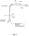
- the system comprises a hollow guide catheter insertable into the body of a patient, the distal end of which functions as an outlet for liquid to be passed therethrough.
- the catheter is located at a point in region in the artery system where it is desired to know the flow.
- a wire is inserted, the distal end of which carries a sensor unit having a temperature sensor and optionally a pressure sensor.
- Other additional sensors are also conceivable, e.g. pH sensors, ion selective sensors etc.
- the wire is extended past the distal end of the catheter such that the sensor unit is located at a relatively small distance, e.g. 10 cm, from the catheter outlet.
- the wire can be inserted as above and positioned in an appropriate position, and then a second catheter is passed over the wire, inside the guide catheter and the distal end of this second catheter is positioned in the artery system where it is desired to know the flow.
- the first catheter will thereby only be used for guiding.
- This alternative approach can be used if the vessel tree is fairly complex with many narrow blood vessels, such that it can be difficult to position a catheter without the help of the wire.
- the guide catheter (or the second catheter in the alternative) is provided at the proximal end with an inlet for saline.
- a Luer® lock is provided in order that a syringe easily be connected.
- the sensor unit is coupled to a control unit for the processing of the signals from the sensor unit, said signals being transferred via electrical leads running along the wire.
- the catheter When the above-mentioned catheter has been positioned appropriately, it will become filled with blood because of the prevailing pressure difference between the interior of the body and the ambient atmosphere. I.e. the pressure inside the vessel is slightly higher than the atmospheric pressure externally of the body, P body -P outside > 0.
- the operator fills a syringe with a suitable amount of cold saline, say 20°C.
- the volume to be expelled by the syringe is preferably equal to the volume inside the catheter from the inlet point up to the outlet plus the bolus-dose to be expelled into the flowing blood.
- the volume of a catheter is commonly about 3 ml, and a suitable bolus-dose could be e.g. 1-3 ml, although the exact volumes will of course differ from case to case.
- the sensor is connected via the electrical leads to a detection unit which has the capability of switching between measurement of cable resistance and detecting the signal from the sensor.
- the operator connects the syringe to the inlet port and begins injecting the cold saline at a relatively low rate, such that the time to fill the guide catheter all the way up to the outlet will typically take 1-15, preferably 10-15 seconds, although this can vary substantially from case to case outside this interval.
- the volume of the catheter is known and thus when the operator has expelled a volume corresponding to the catheter volume during the mentioned time period, he will more rapidly expel the last dose, say during 0,5 seconds, although this time is not strictly critical.
- the detection unit operates according to the method disclosed in the previously mentioned U.S. provisional 60/136,401.
- the compensation disclosed therein is based on a switching between measurements of the sensor signal and of the resistance of the leads so as to enable compensation of changes in lead resistance.
- the resistivity of the electrical leads will instantly be changed but this will be compensated for such that the detection unit will always deliver a readout of a constant temperature inside the blood vessel at the point of location of the sensor.
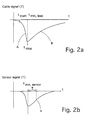
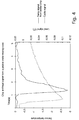
- the change in resistance of the leads will not be recorded during the initial phase of filling the catheter with saline, but immediately prior to or at the same time as the operator injects the last bolus-dose into the catheter, the recording of lead signal will be initiated and monitored and also the sensor signal will be recorded and monitored simultaneously. Because of the rapid injection of the last volume segment of cold saline (at point t start in Fig. 2a; the bolus ends at t stop ), the cable resistivity will abruptly change since it will experience more cold liquid during a shorter period of time and this will be reflected in a drop in the readout signal as shown in figure 2a.
- the sensor being located at a relatively short distance from the catheter outlet, say approximately 10 cm, although this distance is not strictly critical, will be subjected to the cooler bolus-dose of saline a short period of time after it has been expelled from the outlet of the catheter, of the order of a fraction of a second up to a few seconds.
- a sensor signal is schematically shown in Fig. 2b, and this signal is recorded and used as the basis for determining the starting point of time measurement.
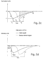
- a calculation as recited under the background of the invention can be performed on the basis of the sensor signal, i.e. by numeric integration, or by fitting the entire signal from the sensor element to a mathematical function, e.g. Log Normal, Gamma, and then use this function to calculate the point c in Fig. 2d, wherein c is the center of mass of the curve defined by the sensor signal.
- a combination of numeric integration and curve fitting can be used. In the latter case the curve fitting is performed at the portion of the curve approaching the base line, after the cut off point D (see Fig. 2c).
- One way is to register the onset of resistivity reduction.
- the derivative of the curve may be calculated, and if the derivative exceeds a preset value, time measurment is triggered.
- Another way is to use the peak value as a starting point for time measurement. Again the derivative, or preferably the second derivative, is calculated and the change in sign is detected.
- a further usable point is to take the average of the two values, e.g. (t start - t stop )/2.
- the mentioned part B' of the sensor signal curve will entirely or partly be fitted to a mathematical function, e.g. e -t/ ⁇ , which is an exponential function.
- a mathematical function e.g. e -t/ ⁇
- ⁇ of the exponential function can be determined.
- T can be calculated by fitting the sensor element signal from the point P s in Fig. 2c up to a point D, where D is the cut-off point, e.g. 10% of the peak value (at P s ).
- T mn (t stop -t start )/2 + t min, sensor - t stop + ⁇
- Fig. 3 and 4 respectively measurement data on a patient are shown for a hyperemic condition and a resting condition respectively.
- the distance is shorter i.e. the flow is higher, than in the resting condition.
- the time constant for the increasing portion is slower for the resting condition than under hypermia.
- CFR can be obtained by measuring the mean transit time, T mn for a bolus dose of cold liquid by employing the response curve from the lead resistance measurements and a temperature sensor respectively.
- the center of mass is located at position x.
Abstract
Description
- The present invention relates to measurement of flow in blood vessel by thermo-dilution. In particular it relates to an improved method of triggering such measurement in order to improve the measurements.
- Devices and methods of flow measurements are disclosed in US serial No. 09/073,061, 09/117,416, all assigned to Radi Medical Systems AB, Sweden.
- In particular 09/073,061 relates to a method of flow measurements by thermo-dilution, wherein the time measurements are triggered by a pressure pulse detected as a result of the injection of a bolus dose of saline. The general theory described therein fully applies to the present invention, and therefore the entire disclosure thereof is incorporated herein.
- Nevertheless, the discussion therein is repeated below for ease of understanding.
- Application of the thermodilution principle in the coronary sinus was introduced by Ganz (Ganz et al, "Measurement of coronary sinus blood flow by continuous thermodilution in man, Circulation 44:181-195, 1971). A small catheter is introduced deeply into the coronary sinus and cold saline is delivered at its tip. Theoretically, flow can be calculated from the changes in blood temperature, registered by a thermistor close to the outlet of the coronary sinus. An advantage of this method is that only right heart catheterization is required.
- The principle of thermo-dilution involves injecting a known amount of cooled liquid, e.g. physiological saline in a blood vessel. After injection the temperature is continuously recorded with a temperature sensor attached to the tip of a guide wire that is inserted in the vessel. A temperature change due to the cold liquid passing the measurement site, i.e. the location of the sensor, will be a function of the flow.
- There are various methods of evaluating the temperature signal for diagnostic purposes. Either one may attempt to calculate the volume flow, or one may use a relative measure, where the flow in a "rest condition" is compared with a "work condition", induced by medicaments.
- The latter is the simpler way, and may be carried out by measuring the width at half height of the temperature change profile in the two situations indicated, and forming a ratio between these quantities.
- Another way of obtaining a ratio would be to measure the transit time from injection and until the cold liquid passes the sensor, in rest condition and in work condition respectively.
- The former method, i.e. the utilization of the volume flow parameter as such, requires integration of the temperature profile over time in accordance with the equations given below
 wherein
- V is the volume of injected liquid
- Tr,m is the measured temperature at rest condition
- Tr,l is the temperature of injected liquid at rest condition
- T0 is the temperature of the blood, i.e. 37°C
- Tw,m is the measured temperature at work condition
- Tw,l is the temperature of injected liquid at work condition
- Q is the volume flow
-
- These quantities may than be used directly for assessment of the condition of the coronary vessels and the myocardium of the patient, or they may be ratioed as previously to obtain a CFR, i.e. CFR = Qwork/Qrest.
- The latter method, i.e. determination of the transit time requires an accurate time measurement, in view of the relatively small distances in question, about 10 cm or less from injection to measurement site.
- E.g. in order to obtain a correct measurement, the time has to be measured with some accuracy. Using a simple stop watch, which is a common means of timing, is far too inaccurate for obtaining reliable transit times.
- The flow F may be obtained as follows, which is a derivation for a similar technique, namely the indicator dilution technique. This is based on a rapidly injected amount of some kind of indicator, the concentration of which is measured.
- Suppose that the flow through a branching vascular bed is constant and equals F, and that a certain well-known amount M of indicator is injected into this bed at site A (se Fig. 7). After some time, the first particles of indicator will arrive at the measuring site B. The concentration of indicator at B, called c(t), will increase for some time, reach a peak and decrease again. The graphic representation of indicator concentration as a fucntion of time is called the indicator dilution curve.
- Consider M as a large number of indicator particles (or molecules). The number of particles passing at B during the time interval Δt, teween ti and ti+1, equals the number of particles per unit time multiplied by the length f the time interval, in other words: c(ti)· F · Δt (Fig. 8).
- Because all particles pass at B between t = 0 and t = ∞, this means that:or
 or
or and it is the last expression which is used in most methods to calculate systemic flow as outlined above. Essential features of this approach is that the amount M of injected indicator should be known whereas no knowledge about the volume of the vascular compartment is needed.
- The calculation of volume is more complex. For this purpose, the function h(t) is introduced which is the fraction of indicator, passing per unit of time at a measurement site at time t. In other words, h(t) is the distribution function of transit times of the indicator particles. If it is assumed that that flow of the indicator is representative for flow of the total fluid (complete mixing), h(t) is also the distribution function of transit times of all fluid particles. Suppose the total volume of fluid is made up of a very large number of volume elements dVi which are defined in such a way that dVi contains all fluid particles present in the system at t=0, with transit times between ti and ti+1. The fraction of fluid particles requiring times between ti and ti+1 to pass the measurement site, is h(ti) Δt by definition, and because the rate at which the fluid particles pass at the measurement site, equals F, the rate at which the particles making up dVi pass at the measurement site is F ·h(ti) ·Δt. The total volume of dVi equals the time ti, required for all particles segments in dVi to pass at the measurement site multiplied by the rate at which they leave. In other words:

- The integral in the equation above represents the mean transit time Tmn, which is the average time, needed by one particle to travel from an injection site to a measurement site. Therefore:
- The mean transit time (Tmn) can now be calculated easily from the indicator or thermo dilution curve in the following way. When looking at the hatched rectangle in Fig. 8, it can be seen that the number of indicator particles passing between ti and ti+1, equals the number of particles c(ti) ·F passing per unit of time, multiplied by the length of the time interval, Δt, in other words: c(ti) ·F ·Δt. Therefore, the total (summed) transit time of all these indicator particles together equals ti · c(ti) · F · Δt. The total transit time of all indicator particles together, by integration, isand the mean transit time of the indicator particles can be obtained by dividing equation 3.8 by the total number of particles M, resulting in:


- By substitution of equation 3.3 in 3.10, Tmn is obtained:

- Equation 3.11 describes how mean transit time Tmn can be calculated from the indicator dilution curve c(t). Because in the assessment of myocardial perfusion, using contrast agent as the indicator, the amount of injected contrast agent is unknown and changing because of the necessary leakage of the contrast agent into the aorta and the unknown and changing distribution of contrast agent over the different branches of the coronary arterial tree, use of Tmn is advantageous because no knowledge about the amount of injected indicator is necessary.
- Although the above derivation was made for the mentioned indicator dilution technique, the result is the same for thermo-dilution since the same distribution function may be employed, and the skilled man will easily adjust the equations accordingly.
- The prior art pressure pulse triggering of the time measurements, although improving the method considerably, has some drawbacks. I.a. the sensitivity in the pressure measurement may not be adequate, the magnitude of the pulse being quite low, and therefore the accuracy may be negatively influenced.
- Thus, there is a need for an improved triggering of the measurement.
- The inventors have realized that a previous problem acknowledged in connection with thermo-dilution can be used to an advantage for triggering purposes. Namely, when a bolus does of cold saline is injected into a catheter where a wire carrying the sensor unit and electrical leads for signal transmission is located, the lead resistance will be instantly affected by the cold saline by a change in the resistivity. This is a problem in that the change must be compensated for in order to arrive at a correct output signal.
- However, this compensation can be done, and is one of the issues discussed in our pending Swedish application 9901962-2, corresponding to US provisional 60/136,401.
- Thus, in accordance with the present invention, the resistivity change is recorded as a resistance variation curve, and various parts of the recorded curve, or the entire curve, can be mathematically processed to give as a result a starting point for the determination for a transit time of the injected liquid. In this way the accuracy in the time measurement is significantly improved.
- The method of flow determination according to the invention is advantageous in that it is independent
- of the injected amount of bolus liquid
- of temperature of the injected liquid, so long as detectable signals are obtained
-
- Fig. 1 is an overview that shows a system wherein the novel method is performed;
- Figs. 2a-c are graphs illustrating the resistivity profiles of the electrical leads during measurement;
- Fig. 3 is a graph showing measurements on a patient during hyperemia;
- Fig. 4 is a graph showing measurements on a patient during a resting period;
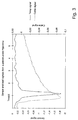
- Fig. 5 is a graph showing the correlation between measurement data on patients according to the invention and a reference method;
- Fig. 6 is a graph showing the correlation between another set of patient data according to the invention and a reference method;
- Fig. 7 illustrates an indicator dilution curve obtained in a vascular network;
- Fig. 8 illustrates calculation of flow in indicator dilution; and
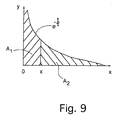
- Fig. 9 illustrates the derivation of center of mass.
-
- In fig. 1 there is disclosed a system suitable for implementation of the present invention. The system comprises a hollow guide catheter insertable into the body of a patient, the distal end of which functions as an outlet for liquid to be passed therethrough. The catheter is located at a point in region in the artery system where it is desired to know the flow. Inside the catheter a wire is inserted, the distal end of which carries a sensor unit having a temperature sensor and optionally a pressure sensor. Other additional sensors are also conceivable, e.g. pH sensors, ion selective sensors etc. The wire is extended past the distal end of the catheter such that the sensor unit is located at a relatively small distance, e.g. 10 cm, from the catheter outlet.
- Alternatively, the wire can be inserted as above and positioned in an appropriate position, and then a second catheter is passed over the wire, inside the guide catheter and the distal end of this second catheter is positioned in the artery system where it is desired to know the flow. The first catheter will thereby only be used for guiding. This alternative approach can be used if the vessel tree is fairly complex with many narrow blood vessels, such that it can be difficult to position a catheter without the help of the wire.
- The guide catheter (or the second catheter in the alternative) is provided at the proximal end with an inlet for saline. Suitably a Luer® lock is provided in order that a syringe easily be connected. The sensor unit is coupled to a control unit for the processing of the signals from the sensor unit, said signals being transferred via electrical leads running along the wire.
- The method according to the invention will now be described in some detail with reference to the figures.
- When the above-mentioned catheter has been positioned appropriately, it will become filled with blood because of the prevailing pressure difference between the interior of the body and the ambient atmosphere. I.e. the pressure inside the vessel is slightly higher than the atmospheric pressure externally of the body, Pbody-Poutside > 0. When the wire carrying the sensor has been inserted and the sensor appropriately located at the point of measurement, the operator fills a syringe with a suitable amount of cold saline, say 20°C. The volume to be expelled by the syringe is preferably equal to the volume inside the catheter from the inlet point up to the outlet plus the bolus-dose to be expelled into the flowing blood. The volume of a catheter is commonly about 3 ml, and a suitable bolus-dose could be e.g. 1-3 ml, although the exact volumes will of course differ from case to case.
- The sensor is connected via the electrical leads to a detection unit which has the capability of switching between measurement of cable resistance and detecting the signal from the sensor.
- The operator connects the syringe to the inlet port and begins injecting the cold saline at a relatively low rate, such that the time to fill the guide catheter all the way up to the outlet will typically take 1-15, preferably 10-15 seconds, although this can vary substantially from case to case outside this interval. The volume of the catheter is known and thus when the operator has expelled a volume corresponding to the catheter volume during the mentioned time period, he will more rapidly expel the last dose, say during 0,5 seconds, although this time is not strictly critical.
- The detection unit operates according to the method disclosed in the previously mentioned U.S. provisional 60/136,401. The compensation disclosed therein is based on a switching between measurements of the sensor signal and of the resistance of the leads so as to enable compensation of changes in lead resistance. Thus, when the operator begins injecting the cold saline of course the resistivity of the electrical leads will instantly be changed but this will be compensated for such that the detection unit will always deliver a readout of a constant temperature inside the blood vessel at the point of location of the sensor.
- For the purpose of the invention the change in resistance of the leads will not be recorded during the initial phase of filling the catheter with saline, but immediately prior to or at the same time as the operator injects the last bolus-dose into the catheter, the recording of lead signal will be initiated and monitored and also the sensor signal will be recorded and monitored simultaneously. Because of the rapid injection of the last volume segment of cold saline (at point tstart in Fig. 2a; the bolus ends at tstop), the cable resistivity will abruptly change since it will experience more cold liquid during a shorter period of time and this will be reflected in a drop in the readout signal as shown in figure 2a. The sensor being located at a relatively short distance from the catheter outlet, say approximately 10 cm, although this distance is not strictly critical, will be subjected to the cooler bolus-dose of saline a short period of time after it has been expelled from the outlet of the catheter, of the order of a fraction of a second up to a few seconds. A sensor signal is schematically shown in Fig. 2b, and this signal is recorded and used as the basis for determining the starting point of time measurement.
- If it can be assumed that the actual injection of the bolus-dose into the blood-flow will not affect the measurement of the flow at the measurement point, then a calculation as recited under the background of the invention can be performed on the basis of the sensor signal, i.e. by numeric integration, or by fitting the entire signal from the sensor element to a mathematical function, e.g. Log Normal, Gamma, and then use this function to calculate the point c in Fig. 2d, wherein c is the center of mass of the curve defined by the sensor signal. Also a combination of numeric integration and curve fitting can be used. In the latter case the curve fitting is performed at the portion of the curve approaching the base line, after the cut off point D (see Fig. 2c).
- However, of course also the starting point for the integration must be determined, e.g. t=0. This point in time can be determined in different ways, using the recorded resistance variation curve.
- One way is to register the onset of resistivity reduction. Here the derivative of the curve may be calculated, and if the derivative exceeds a preset value, time measurment is triggered.
- Another way is to use the peak value as a starting point for time measurement. Again the derivative, or preferably the second derivative, is calculated and the change in sign is detected.
- A further usable point is to take the average of the two values, e.g. (tstart - tstop)/2.
- In an alternative embodiment the same "triggering" of the time measurement can be used (by "triggering" we mean for the purposes of this invention, the determination of a starting point for the time measurement, or put in other words the determination of t=0 for the purpose of integration).
- In this alternative embodiment only the increasing part of the sensor signal (indicated with B' will be used). For this purpose the mentioned part B' of the sensor signal curve will entirely or partly be fitted to a mathematical function, e.g. e-t/τ, which is an exponential function. The simplest way of doing this is to take the logarithm of the measurement data at this part and to plot this against time. From the slope of the linear portion of that plot the time constant, τ of the exponential function can be determined. The point on said curve portion B' of Fig. 2b, corresponding to the point on the time axis at tmin, sensor + τ will be center of mass of the exponential curve, which is the point up to which Tmn will be calculated from t=0. Strictly mathematically, 0,7τ should be used for the identification of the center of mass, but for the purpose of this application the approximation to T is adequate. T can be calculated by fitting the sensor element signal from the point Ps in Fig. 2c up to a point D, where D is the cut-off point, e.g. 10% of the peak value (at Ps).
- If we assume that t=0 is set to be equal to the point between tstart and tstop, e.g. (tstop-tstart)/2, then the total mean transit time Tmn will be sum
- The terms of this sum are illustrated in Fig. 2c as t1, t2 and t3 respectively, and thus
Of the above possible approaches to the determination of Tmn, the method discussed in conection with Fi.g 2d is the most "correct" in a mathematical sense. However, the initial flank will very easily be affected by the injection, and the curve fitting may therefore be incorrect. - The other method (Fig. 2c), where only the portion after the peak is fitted to a curve is more independent of the injection, because the injection stopped before any calculations are performed on the curve.
- In Fig. 3 and 4 respectively measurement data on a patient are shown for a hyperemic condition and a resting condition respectively. As can be clearly seen in these figures there is a difference in the time between the minimum of the cable signal and the minimum of the temperature sensor response signal for the two cases, where in the hyperemic state the distance is shorter i.e. the flow is higher, than in the resting condition. It is also clearly visible that the time constant for the increasing portion is slower for the resting condition than under hypermia.
- The CFR is calculated as CFR = Tmn, rest/Tmn, hyper
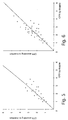
- Finally in figures 5 and 6 respectively the method according to the invention has been qualitativly evaluated against a reference method which is a determination of CFR by a doppler-technique. In this case however, it should be born in mind that also the doppler-technique has its limitations and is not entirely accurate.
- As disclosed previously in this application, CFR can be obtained by measuring the mean transit time, Tmn for a bolus dose of cold liquid by employing the response curve from the lead resistance measurements and a temperature sensor respectively.
- For the calculation of Tmn, the time constant τ of an exponential function e-t/τ is calculated.
- It is also discovered by the inventors that T itself is correlated to the flow in a coronary vessel, and therefore T itself can be used to determine a value of CFR, namely as
- In this case the center of mass is located at position x. The center of mass is found where area of A1 = area of A2.
 and
and and
and
Claims (13)
- A method of triggering a time measurement in a system for the measurement of a transit time of a finite amount of an indicator first liquid, injected in a flow of a second liquid in the course of a thermo-dilution measurement, wherein said flow of liquid has a temperature that is different from the temperature of said indicator liquid, said system having a temperature sensitive part, characterized byrecording a change in a system variable caused by exposure of said temperature sensitive part of said system to said indicator first liquid; andusing the recorded change to determine a starting point for time measurement.
- The method as claimed in claim 1, wherein said temperature sensitive part of said system is at least one electrical lead connecting an electrical measuring device, located in said flow of said second liquid, with externally located control equipment.
- The method as claimed in claim 2, wherein said system variable is the electrical resistance of said at least one lead.
- The method as claimed in claim 3, wherein the resistance variation of said electrical lead is registered, thereby obtaining a resistance variation curve, and selecting a point on said curve as said starting point for time measurement.
- The method as claimed in claim 4, wherein said point is selected by calculating the derivative of said resistance variation curve, and taking a point in time where said derivative exceeds a predetermined level as said starting point.
- The method as claimed in claim 4, wherein said point is selected by calculating the second derivative of said resistance variation curve, and taking a point in time where said second derivative changes sign as said starting point.
- The method as claimed in claim 4, wherein said point is selected by calculating the average between the point in time when the injection of said indicator liquid is started and the point in time when the injection is stopped.
- The method as claimed in claim 2, wherein said electrical measuring device is a temperature sensor.
- The method as claimed in claim 1, wherein the temperature of said indicator liquid is lower than the second liquid, and wherein the second liquid is blood.
- A method of determining a transit time of a finite amount of an indicator first liquid, injected in a flow of blood in a blood vessel in the course of a thermo-dilution measurement for the determination of the flow of said second liquid, comprising the following steps:providing a temperature sensor at the distal end of a wire, and electrical leads coupled to said sensor and running along the wire, and connecting the leads to a control unit for the processing of signals from the sensor;inserting a catheter having a distal and a proximal end with an outlet and an inlet respectively, into said blood vessel such that the distal end is located in the region where said flow is to be determined;inserting the wire in said catheter and extending its distal end past the distal end of the catheter;injecting indicator first liquid of a temperature lower than the temperature prevailing inside said blood vessel, into said catheter inlet such that the catheter is filled all the way up to the outlet;injecting a further amount of said indicator liquid to expel a corresponding volume of indicator liquid into said blood vessel through the catheter outlet; characterized in thatthe transit time is determined as the difference in time of a starting point and a time of response of said temperature sensor, wherein said starting point is determined with the method defined in claim 1.
- The method as claimed in claim 10, comprising simultaneously recording the resistance of the electrical leads and the response from the sensor, determining a starting point for time measurements, t=0, from the lead resistance recording, determining the center of gravity of the sensor response curve, and calculating as said flow parameter a mean transit time Tmn for the indicator liquid as the time from t=0 to the point in time corresponding to said center of gravity.
- A method of determining a transit time of a finite amount of an indicator first liquid, injected in a flow of blood in a blood vessel in the course of a thermo-dilution measurement for the determination of the flow of said second liquid, comprising the following steps:providing a temperature sensor at the distal end of a wire, and electrical leads coupled to said sensor and running along the wire, and connecting the leads to a control unit for the processing of signals from the sensor;inserting the wire into a blood vessel such that the distal end is located in the region where the flow parameter is to be measured;passing a catheter having a distal and a proximal end with an outlet and an inlet respectively, over said wire to a point located proximally of the temperature sensor provided on said wire;injecting indicator first liquid of a temperature lower than the temperature prevailing inside said blood vessel, into said catheter inlet such that the catheter is filled all the way up to the outlet;injecting a further amount of said indicator liquid to expel a corresponding volume of indicator liquid into said blood vessel through the catheter outlet; characterized in thatthe transit time is determined as the difference in time of a starting point and a time of response of said temperature sensor, wherein said starting point is determined with the method defined in claim 1.
- The method as claimed in claim 12, comprising simultaneously recording the resistance of the electrical leads and the response from the sensor, determining a starting point for time measurements, t=0, from the lead resistance recording, determining the center of gravity of the sensor response curve, and calculating as said flow parameter a mean transit time Tmn for the indicator liquid as the time from t=0 to the point in time corresponding to said center of gravity.
Applications Claiming Priority (2)
| Application Number | Priority Date | Filing Date | Title |
|---|---|---|---|
| US17913600P | 2000-01-31 | 2000-01-31 | |
| US179136P | 2000-01-31 |
Publications (2)
| Publication Number | Publication Date |
|---|---|
| EP1125548A1 true EP1125548A1 (en) | 2001-08-22 |
| EP1125548B1 EP1125548B1 (en) | 2005-04-27 |
Family
ID=22655365
Family Applications (1)
| Application Number | Title | Priority Date | Filing Date |
|---|---|---|---|
| EP01850022A Expired - Lifetime EP1125548B1 (en) | 2000-01-31 | 2001-01-31 | Triggered flow measurement |
Country Status (7)
| Country | Link |
|---|---|
| US (1) | US6672172B2 (en) |
| EP (1) | EP1125548B1 (en) |
| JP (1) | JP4766755B2 (en) |
| AT (1) | ATE293916T1 (en) |
| DE (1) | DE60110281T2 (en) |
| ES (1) | ES2240389T3 (en) |
| WO (1) | WO2001054576A1 (en) |
Cited By (10)
| Publication number | Priority date | Publication date | Assignee | Title |
|---|---|---|---|---|
| EP1260175A2 (en) | 2001-05-23 | 2002-11-27 | Radi Medical Systems Ab | Interactive measurement system |
| WO2004002348A1 (en) * | 2002-06-28 | 2004-01-08 | Ethicon, Inc. | Apparatus and method for transcervical sterilization by application of ultrasound |
| WO2005094933A2 (en) * | 2004-03-25 | 2005-10-13 | Boston Scientific Scimed, Inc. | Catheter with sensor tips, tool and device and methods of use of same |
| EP2021755A2 (en) * | 2006-05-08 | 2009-02-11 | Becton, Dickinson & Company | Vascular access device time sensitive status indication |
| US8163237B2 (en) | 2006-05-08 | 2012-04-24 | Becton, Dickinson And Company | Vascular access device pathogenic status indication |
| CN103270513A (en) * | 2010-08-12 | 2013-08-28 | 哈特弗罗公司 | Method and system for patient-pecific modeling of blood flow |
| US10354050B2 (en) | 2009-03-17 | 2019-07-16 | The Board Of Trustees Of Leland Stanford Junior University | Image processing method for determining patient-specific cardiovascular information |
| US10702170B2 (en) | 2013-07-01 | 2020-07-07 | Zurich Medical Corporation | Apparatus and method for intravascular measurements |
| US10835183B2 (en) | 2013-07-01 | 2020-11-17 | Zurich Medical Corporation | Apparatus and method for intravascular measurements |
| US11107587B2 (en) | 2008-07-21 | 2021-08-31 | The Board Of Trustees Of The Leland Stanford Junior University | Method for tuning patient-specific cardiovascular simulations |
Families Citing this family (39)
| Publication number | Priority date | Publication date | Assignee | Title |
|---|---|---|---|---|
| US6585660B2 (en) | 2001-05-18 | 2003-07-01 | Jomed Inc. | Signal conditioning device for interfacing intravascular sensors having varying operational characteristics to a physiology monitor |
| US6663570B2 (en) * | 2002-02-27 | 2003-12-16 | Volcano Therapeutics, Inc. | Connector for interfacing intravascular sensors to a physiology monitor |
| US7134994B2 (en) * | 2002-05-20 | 2006-11-14 | Volcano Corporation | Multipurpose host system for invasive cardiovascular diagnostic measurement acquisition and display |
| US8277386B2 (en) | 2004-09-27 | 2012-10-02 | Volcano Corporation | Combination sensor guidewire and methods of use |
| US20060116602A1 (en) * | 2004-12-01 | 2006-06-01 | Alden Dana A | Medical sensing device and system |
| DE102005007592A1 (en) * | 2005-02-18 | 2006-08-24 | Pulsion Medical Systems Ag | Device for the determination of cardiopulmonary volumes and flows of a living being |
| KR101754570B1 (en) | 2008-09-11 | 2017-07-06 | 어시스트 메디칼 시스템즈, 인크. | Physiological sensor delivery device and method |
| EP2456823A4 (en) * | 2009-07-21 | 2012-12-26 | 3M Innovative Properties Co | Curable composition, method of coating a phototool, and coated phototool |
| CN103959043B (en) | 2011-05-31 | 2016-11-02 | 光学实验室成像公司 | Multi-mode imaging system, equipment and method |
| US9314584B1 (en) | 2011-06-27 | 2016-04-19 | Bayer Healthcare Llc | Method and apparatus for fractional flow reserve measurements |
| US10648918B2 (en) | 2011-08-03 | 2020-05-12 | Lightlab Imaging, Inc. | Systems, methods and apparatus for determining a fractional flow reserve (FFR) based on the minimum lumen area (MLA) and the constant |
| US10888232B2 (en) | 2011-08-20 | 2021-01-12 | Philips Image Guided Therapy Corporation | Devices, systems, and methods for assessing a vessel |
| US9339348B2 (en) | 2011-08-20 | 2016-05-17 | Imperial Colege of Science, Technology and Medicine | Devices, systems, and methods for assessing a vessel |
| WO2013082032A1 (en) * | 2011-11-28 | 2013-06-06 | Mazar Scott T | Steerable guide wire with pressure sensor |
| EP2854649B1 (en) * | 2012-05-25 | 2018-07-11 | Acist Medical Systems, Inc. | Fluid flow measurement systems and methods |
| US10506934B2 (en) | 2012-05-25 | 2019-12-17 | Phyzhon Health Inc. | Optical fiber pressure sensor |
| US9757591B2 (en) | 2013-02-11 | 2017-09-12 | Bayer Healthcare Llc | Methods and systems for monitoring an automated infusion system |
| EP3384853B1 (en) * | 2013-03-06 | 2019-12-11 | Muffin Incorporated | Echolucent catheter |
| WO2015051003A1 (en) | 2013-10-04 | 2015-04-09 | Vascular Imaging Corporation | Imaging techniques using an imaging guidewire |
| US10537255B2 (en) | 2013-11-21 | 2020-01-21 | Phyzhon Health Inc. | Optical fiber pressure sensor |
| EP3861928B1 (en) | 2014-04-04 | 2024-03-27 | St. Jude Medical Systems AB | Intravascular pressure and flow data diagnostic system |
| US10244951B2 (en) * | 2014-06-10 | 2019-04-02 | Acist Medical Systems, Inc. | Physiological sensor delivery device and method |
| FR3026631B1 (en) | 2014-10-03 | 2016-12-09 | Ecole Polytech | IMPLANTABLE MEDICAL DEVICE WITH SENSORS |
| US10080872B2 (en) | 2014-11-04 | 2018-09-25 | Abbott Cardiovascular Systems Inc. | System and method for FFR guidewire recovery |
| US10258240B1 (en) | 2014-11-24 | 2019-04-16 | Vascular Imaging Corporation | Optical fiber pressure sensor |
| CN107427244B (en) * | 2015-01-05 | 2021-05-14 | 尼普洛株式会社 | Blood flow meter and measuring device |
| FR3042873A1 (en) | 2015-10-23 | 2017-04-28 | Ecole Polytech | METHOD AND SYSTEM FOR DISCRIMINATING CELLS |
| JP6864839B2 (en) * | 2016-03-29 | 2021-04-28 | ニプロ株式会社 | Sensor control circuit and blood measuring device |
| FR3049843A1 (en) | 2016-04-06 | 2017-10-13 | Instent | MEDICAL DEVICE PROVIDED WITH SENSORS |
| JP6824299B2 (en) | 2016-06-29 | 2021-02-03 | ピッコロ・メディカル,インコーポレーテッド | Equipment and methods for navigation, evaluation and / or diagnosis of blood vessels |
| WO2018091746A1 (en) | 2016-11-21 | 2018-05-24 | Sensome | Characterizing and identifying biological structure |
| EP3485800A1 (en) | 2017-11-15 | 2019-05-22 | Koninklijke Philips N.V. | Sensing device and method for multiple remote sensors |
| CN111954487A (en) | 2018-04-20 | 2020-11-17 | 阿西斯特医疗系统有限公司 | Evaluation of blood vessels |
| CN112204609A (en) | 2018-05-23 | 2021-01-08 | 阿西斯特医疗系统有限公司 | Flow measurement using image data |
| CN110384494A (en) * | 2018-09-19 | 2019-10-29 | 苏州润迈德医疗科技有限公司 | The method for measuring microcirculation drag index |
| KR102125057B1 (en) | 2018-11-23 | 2020-06-19 | 박영민 | Jump start device for vehicle |
| CN111595393A (en) * | 2020-06-15 | 2020-08-28 | 上海同瑞环保工程有限公司 | Device and method for measuring flow in drainage pipeline |
| US11633534B2 (en) | 2020-08-18 | 2023-04-25 | Acist Medical Systems, Inc. | Angiogram injections using electrocardiographic synchronization |
| US20240032812A1 (en) * | 2022-07-28 | 2024-02-01 | Transonic Systems Inc. | Dilution curve compensation in flow rate calculation |
Citations (3)
| Publication number | Priority date | Publication date | Assignee | Title |
|---|---|---|---|---|
| WO1993021823A1 (en) * | 1992-04-30 | 1993-11-11 | Ulrich Pfeiffer | Process for determining the fill level of a circulatory system of a patient |
| US5595181A (en) * | 1994-03-24 | 1997-01-21 | Hubbard; A. Robert | System for providing cardiac output and shunt quantitation |
| EP0900545A2 (en) * | 1997-09-05 | 1999-03-10 | Pulsion Verw. Gmbh & Co. Medical Systems KG | Process and devices for determining the instant of injection and the duration of injection in thermodilution measurements |
Family Cites Families (13)
| Publication number | Priority date | Publication date | Assignee | Title |
|---|---|---|---|---|
| GB686082A (en) * | 1950-10-03 | 1953-01-14 | Rose Brothers Ltd | Improvements in wrapping machines |
| US4554927A (en) * | 1983-08-30 | 1985-11-26 | Thermometrics Inc. | Pressure and temperature sensor |
| JPS6470024A (en) * | 1987-03-05 | 1989-03-15 | Terumo Corp | Cardiac output measuring apparatus equipped with automatic starting function of measurement |
| US5114401A (en) * | 1990-02-23 | 1992-05-19 | New England Deaconess Hospital Corporation | Method for central venous catheterization |
| US6387052B1 (en) * | 1991-01-29 | 2002-05-14 | Edwards Lifesciences Corporation | Thermodilution catheter having a safe, flexible heating element |
| US5226333A (en) * | 1991-05-30 | 1993-07-13 | The United States Of America As Represented By The Secretary Of The Interior | Deep-well thermal flowmeter |
| DE4214068A1 (en) * | 1992-04-29 | 1993-11-04 | Pfeiffer Ulrich | DEVICE FOR DETERMINING THE VOLUME AND / OR THE THROUGHPUT OF A PATIENT'S CIRCUIT SECTION |
| SE9600333D0 (en) * | 1995-06-22 | 1996-01-30 | Radi Medical Systems | Sensor arrangement |
| AU7844498A (en) * | 1996-12-09 | 1998-07-03 | Tjin, Swee Chuan | Method and apparatus for continuous cardiac output monitoring |
| US6089103A (en) * | 1998-05-06 | 2000-07-18 | Radi Medical Systems Ab | Method of flow measurements |
| US6142958A (en) * | 1998-12-23 | 2000-11-07 | Radi Medical Systems Ab | Sensor and guide wire assembly |
| EP1139867B1 (en) * | 1999-10-28 | 2004-04-28 | Pulsion Medical Systems AG | Apparatus, computer system and computer program for determining a cardio-vascular parameter |
| US6383144B1 (en) * | 2000-01-18 | 2002-05-07 | Edwards Lifesciences Corporation | Devices and methods for measuring temperature of a patient |
-
2001
- 2001-01-30 US US09/771,703 patent/US6672172B2/en not_active Expired - Lifetime
- 2001-01-31 EP EP01850022A patent/EP1125548B1/en not_active Expired - Lifetime
- 2001-01-31 AT AT01850022T patent/ATE293916T1/en not_active IP Right Cessation
- 2001-01-31 DE DE60110281T patent/DE60110281T2/en not_active Expired - Lifetime
- 2001-01-31 JP JP2001024118A patent/JP4766755B2/en not_active Expired - Fee Related
- 2001-01-31 WO PCT/SE2001/000175 patent/WO2001054576A1/en active Application Filing
- 2001-01-31 ES ES01850022T patent/ES2240389T3/en not_active Expired - Lifetime
Patent Citations (3)
| Publication number | Priority date | Publication date | Assignee | Title |
|---|---|---|---|---|
| WO1993021823A1 (en) * | 1992-04-30 | 1993-11-11 | Ulrich Pfeiffer | Process for determining the fill level of a circulatory system of a patient |
| US5595181A (en) * | 1994-03-24 | 1997-01-21 | Hubbard; A. Robert | System for providing cardiac output and shunt quantitation |
| EP0900545A2 (en) * | 1997-09-05 | 1999-03-10 | Pulsion Verw. Gmbh & Co. Medical Systems KG | Process and devices for determining the instant of injection and the duration of injection in thermodilution measurements |
Cited By (56)
| Publication number | Priority date | Publication date | Assignee | Title |
|---|---|---|---|---|
| EP1260175A2 (en) | 2001-05-23 | 2002-11-27 | Radi Medical Systems Ab | Interactive measurement system |
| WO2004002348A1 (en) * | 2002-06-28 | 2004-01-08 | Ethicon, Inc. | Apparatus and method for transcervical sterilization by application of ultrasound |
| US6972018B2 (en) | 2002-06-28 | 2005-12-06 | Gynecare A Division Of Ethicon, Inc. | Apparatus and method for transcervical sterilization by application of ultrasound |
| WO2005094933A2 (en) * | 2004-03-25 | 2005-10-13 | Boston Scientific Scimed, Inc. | Catheter with sensor tips, tool and device and methods of use of same |
| WO2005094933A3 (en) * | 2004-03-25 | 2006-01-26 | Boston Scient Scimed Inc | Catheter with sensor tips, tool and device and methods of use of same |
| US7565208B2 (en) | 2004-03-25 | 2009-07-21 | Boston Scientific Scimed, Inc. | Catheter with sensor tips, tool and device and methods of use of same |
| EP2021755A2 (en) * | 2006-05-08 | 2009-02-11 | Becton, Dickinson & Company | Vascular access device time sensitive status indication |
| EP2021755A4 (en) * | 2006-05-08 | 2009-09-02 | Becton Dickinson Co | Vascular access device time sensitive status indication |
| US8137303B2 (en) | 2006-05-08 | 2012-03-20 | Becton, Dickinson And Company | Vascular access device cleaning status indication |
| US8163237B2 (en) | 2006-05-08 | 2012-04-24 | Becton, Dickinson And Company | Vascular access device pathogenic status indication |
| US8257663B2 (en) | 2006-05-08 | 2012-09-04 | Becton, Dickinson And Company | Vascular access device time sensitive status indication |
| US8540944B2 (en) | 2006-05-08 | 2013-09-24 | Becton, Dickinson And Company | Vascular access device time sensitive status indication |
| US8715248B2 (en) | 2006-05-08 | 2014-05-06 | Becton, Dickinson And Company | Vascular access device time sensitive status indication |
| US11107587B2 (en) | 2008-07-21 | 2021-08-31 | The Board Of Trustees Of The Leland Stanford Junior University | Method for tuning patient-specific cardiovascular simulations |
| US10354050B2 (en) | 2009-03-17 | 2019-07-16 | The Board Of Trustees Of Leland Stanford Junior University | Image processing method for determining patient-specific cardiovascular information |
| US10154883B2 (en) | 2010-08-12 | 2018-12-18 | Heartflow, Inc. | Method and system for image processing and patient-specific modeling of blood flow |
| US10441361B2 (en) | 2010-08-12 | 2019-10-15 | Heartflow, Inc. | Method and system for image processing and patient-specific modeling of blood flow |
| CN107184186A (en) * | 2010-08-12 | 2017-09-22 | 哈特弗罗公司 | The method and system modeled for patient-specific blood flow |
| US9801689B2 (en) | 2010-08-12 | 2017-10-31 | Heartflow, Inc. | Method and system for patient-specific modeling of blood flow |
| US9839484B2 (en) | 2010-08-12 | 2017-12-12 | Heartflow, Inc. | Method and system for image processing and patient-specific modeling of blood flow |
| US9855105B2 (en) | 2010-08-12 | 2018-01-02 | Heartflow, Inc. | Method and system for image processing to determine patient-specific blood flow characteristics |
| US9861284B2 (en) | 2010-08-12 | 2018-01-09 | Heartflow, Inc. | Method and system for image processing to determine patient-specific blood flow characteristics |
| US9888971B2 (en) | 2010-08-12 | 2018-02-13 | Heartflow, Inc. | Method and system for image processing to determine patient-specific blood flow characteristics |
| US10052158B2 (en) | 2010-08-12 | 2018-08-21 | Heartflow, Inc. | Method and system for image processing to determine patient-specific blood flow characteristics |
| US10080614B2 (en) | 2010-08-12 | 2018-09-25 | Heartflow, Inc. | Method and system for image processing to determine patient-specific blood flow characteristics |
| US10080613B2 (en) | 2010-08-12 | 2018-09-25 | Heartflow, Inc. | Systems and methods for determining and visualizing perfusion of myocardial muscle |
| US10092360B2 (en) | 2010-08-12 | 2018-10-09 | Heartflow, Inc. | Method and system for image processing and patient-specific modeling of blood flow |
| US10149723B2 (en) | 2010-08-12 | 2018-12-11 | Heartflow, Inc. | Method and system for image processing and patient-specific modeling of blood flow |
| US9743835B2 (en) | 2010-08-12 | 2017-08-29 | Heartflow, Inc. | Method and system for image processing to determine patient-specific blood flow characteristics |
| US10159529B2 (en) | 2010-08-12 | 2018-12-25 | Heartflow, Inc. | Method and system for patient-specific modeling of blood flow |
| US10166077B2 (en) | 2010-08-12 | 2019-01-01 | Heartflow, Inc. | Method and system for image processing to determine patient-specific blood flow characteristics |
| CN107122621B (en) * | 2010-08-12 | 2019-03-08 | 哈特弗罗公司 | Method and system for the modeling of patient-specific blood flow |
| US10321958B2 (en) | 2010-08-12 | 2019-06-18 | Heartflow, Inc. | Method and system for image processing to determine patient-specific blood flow characteristics |
| CN107184186B (en) * | 2010-08-12 | 2019-06-18 | 哈特弗罗公司 | Method and system for the modeling of patient-specific blood flow |
| US10327847B2 (en) | 2010-08-12 | 2019-06-25 | Heartflow, Inc. | Method and system for patient-specific modeling of blood flow |
| US10376317B2 (en) | 2010-08-12 | 2019-08-13 | Heartflow, Inc. | Method and system for image processing and patient-specific modeling of blood flow |
| CN107122621A (en) * | 2010-08-12 | 2017-09-01 | 哈特弗罗公司 | The method and system modeled for patient-specific blood flow |
| US10478252B2 (en) | 2010-08-12 | 2019-11-19 | Heartflow, Inc. | Method and system for patient-specific modeling of blood flow |
| US10492866B2 (en) | 2010-08-12 | 2019-12-03 | Heartflow, Inc. | Method and system for image processing to determine blood flow |
| US10531923B2 (en) | 2010-08-12 | 2020-01-14 | Heartflow, Inc. | Method and system for image processing to determine blood flow |
| US10682180B2 (en) | 2010-08-12 | 2020-06-16 | Heartflow, Inc. | Method and system for patient-specific modeling of blood flow |
| US10702340B2 (en) | 2010-08-12 | 2020-07-07 | Heartflow, Inc. | Image processing and patient-specific modeling of blood flow |
| US10702339B2 (en) | 2010-08-12 | 2020-07-07 | Heartflow, Inc. | Method and system for patient-specific modeling of blood flow |
| US11033332B2 (en) | 2010-08-12 | 2021-06-15 | Heartflow, Inc. | Method and system for image processing to determine blood flow |
| US11793575B2 (en) | 2010-08-12 | 2023-10-24 | Heartflow, Inc. | Method and system for image processing to determine blood flow |
| US11083524B2 (en) | 2010-08-12 | 2021-08-10 | Heartflow, Inc. | Method and system for patient-specific modeling of blood flow |
| US11090118B2 (en) | 2010-08-12 | 2021-08-17 | Heartflow, Inc. | Method and system for image processing and patient-specific modeling of blood flow |
| CN103270513A (en) * | 2010-08-12 | 2013-08-28 | 哈特弗罗公司 | Method and system for patient-pecific modeling of blood flow |
| US11116575B2 (en) | 2010-08-12 | 2021-09-14 | Heartflow, Inc. | Method and system for image processing to determine blood flow |
| US11135012B2 (en) | 2010-08-12 | 2021-10-05 | Heartflow, Inc. | Method and system for image processing to determine patient-specific blood flow characteristics |
| US11154361B2 (en) | 2010-08-12 | 2021-10-26 | Heartflow, Inc. | Method and system for image processing to determine blood flow |
| US11298187B2 (en) | 2010-08-12 | 2022-04-12 | Heartflow, Inc. | Method and system for image processing to determine patient-specific blood flow characteristics |
| US11583340B2 (en) | 2010-08-12 | 2023-02-21 | Heartflow, Inc. | Method and system for image processing to determine blood flow |
| US11471061B2 (en) | 2013-07-01 | 2022-10-18 | Zurich Medical Corporation | Apparatus and method for intravascular measurements |
| US10835183B2 (en) | 2013-07-01 | 2020-11-17 | Zurich Medical Corporation | Apparatus and method for intravascular measurements |
| US10702170B2 (en) | 2013-07-01 | 2020-07-07 | Zurich Medical Corporation | Apparatus and method for intravascular measurements |
Also Published As
| Publication number | Publication date |
|---|---|
| ES2240389T3 (en) | 2005-10-16 |
| US6672172B2 (en) | 2004-01-06 |
| JP4766755B2 (en) | 2011-09-07 |
| US20020043113A1 (en) | 2002-04-18 |
| DE60110281T2 (en) | 2006-02-16 |
| ATE293916T1 (en) | 2005-05-15 |
| JP2001245862A (en) | 2001-09-11 |
| DE60110281D1 (en) | 2005-06-02 |
| EP1125548B1 (en) | 2005-04-27 |
| WO2001054576A1 (en) | 2001-08-02 |
Similar Documents
| Publication | Publication Date | Title |
|---|---|---|
| EP1125548B1 (en) | Triggered flow measurement | |
| EP1076511B1 (en) | System for measuring flow in narrow channels comprising a temperature and a pressure sensor | |
| EP1260175B1 (en) | Interactive measurement system | |
| US5526817A (en) | Process for determining a patient's circulatory fill status | |
| US8702613B2 (en) | Methods for determining fractional flow reserve | |
| US20010000792A1 (en) | Method and apparatus for measuring continuous blood flow at low power | |
| US6537230B1 (en) | Apparatus, computer system and computer program for determining a cardio-vascular parameter of a patient | |
| US20120165689A1 (en) | Catheter with common guide wire and indicator lumen | |
| EP0126931A2 (en) | Method and apparatus for measuring flow | |
| US7549965B2 (en) | Compensation method for thermodilution catheter having an injectate induced thermal effect in a blood flow measurement | |
| US20020120204A1 (en) | Apparatus, computer program, central venous catheter assembly and method for hemodynamic monitoring | |
| EP0687160A1 (en) | Improved injectate delivery system | |
| US4230126A (en) | Apparatus and method for measuring extravascular lung water | |
| US6746408B2 (en) | Method of blood flow measurement in arterio-venous hemodialysis shunts by indicator dilution | |
| EP0440155A2 (en) | Flow-velocity sensor probe | |
| US4015593A (en) | Apparatus and method for measuring cardiac output | |
| US4403615A (en) | Thermal method for measuring blood perfusion | |
| EP0015294B1 (en) | Apparatus for measuring extravascular lung water | |
| JP3069128B2 (en) | Cardiac output measurement device |
Legal Events
| Date | Code | Title | Description |
|---|---|---|---|
| PUAI | Public reference made under article 153(3) epc to a published international application that has entered the european phase |
Free format text: ORIGINAL CODE: 0009012 |
|
| AK | Designated contracting states |
Kind code of ref document: A1 Designated state(s): AT BE CH CY DE DK ES FI FR GB GR IE IT LI LU MC NL PT SE TR |
|
| AX | Request for extension of the european patent |
Free format text: AL;LT;LV;MK;RO;SI |
|
| 17P | Request for examination filed |
Effective date: 20020221 |
|
| AKX | Designation fees paid |
Free format text: AT BE CH CY DE DK ES FI FR GB GR IE IT LI LU MC NL PT SE TR |
|
| 17Q | First examination report despatched |
Effective date: 20040413 |
|
| GRAP | Despatch of communication of intention to grant a patent |
Free format text: ORIGINAL CODE: EPIDOSNIGR1 |
|
| GRAS | Grant fee paid |
Free format text: ORIGINAL CODE: EPIDOSNIGR3 |
|
| GRAA | (expected) grant |
Free format text: ORIGINAL CODE: 0009210 |
|
| AK | Designated contracting states |
Kind code of ref document: B1 Designated state(s): AT BE CH CY DE DK ES FI FR GB GR IE IT LI LU MC NL PT SE TR |
|
| PG25 | Lapsed in a contracting state [announced via postgrant information from national office to epo] |
Ref country code: IT Free format text: LAPSE BECAUSE OF FAILURE TO SUBMIT A TRANSLATION OF THE DESCRIPTION OR TO PAY THE FEE WITHIN THE PRESCRIBED TIME-LIMIT;WARNING: LAPSES OF ITALIAN PATENTS WITH EFFECTIVE DATE BEFORE 2007 MAY HAVE OCCURRED AT ANY TIME BEFORE 2007. THE CORRECT EFFECTIVE DATE MAY BE DIFFERENT FROM THE ONE RECORDED. Effective date: 20050427 Ref country code: CH Free format text: LAPSE BECAUSE OF FAILURE TO SUBMIT A TRANSLATION OF THE DESCRIPTION OR TO PAY THE FEE WITHIN THE PRESCRIBED TIME-LIMIT Effective date: 20050427 Ref country code: AT Free format text: LAPSE BECAUSE OF FAILURE TO SUBMIT A TRANSLATION OF THE DESCRIPTION OR TO PAY THE FEE WITHIN THE PRESCRIBED TIME-LIMIT Effective date: 20050427 Ref country code: FI Free format text: LAPSE BECAUSE OF FAILURE TO SUBMIT A TRANSLATION OF THE DESCRIPTION OR TO PAY THE FEE WITHIN THE PRESCRIBED TIME-LIMIT Effective date: 20050427 Ref country code: LI Free format text: LAPSE BECAUSE OF FAILURE TO SUBMIT A TRANSLATION OF THE DESCRIPTION OR TO PAY THE FEE WITHIN THE PRESCRIBED TIME-LIMIT Effective date: 20050427 |
|
| REG | Reference to a national code |
Ref country code: GB Ref legal event code: FG4D |
|
| RIN1 | Information on inventor provided before grant (corrected) |
Inventor name: TULKKI, SAULI Inventor name: SMITH, LEIF |
|
| REG | Reference to a national code |
Ref country code: CH Ref legal event code: EP |
|
| REG | Reference to a national code |
Ref country code: IE Ref legal event code: FG4D |
|
| REF | Corresponds to: |
Ref document number: 60110281 Country of ref document: DE Date of ref document: 20050602 Kind code of ref document: P |
|
| REG | Reference to a national code |
Ref country code: SE Ref legal event code: TRGR |
|
| PG25 | Lapsed in a contracting state [announced via postgrant information from national office to epo] |
Ref country code: GR Free format text: LAPSE BECAUSE OF FAILURE TO SUBMIT A TRANSLATION OF THE DESCRIPTION OR TO PAY THE FEE WITHIN THE PRESCRIBED TIME-LIMIT Effective date: 20050727 Ref country code: DK Free format text: LAPSE BECAUSE OF FAILURE TO SUBMIT A TRANSLATION OF THE DESCRIPTION OR TO PAY THE FEE WITHIN THE PRESCRIBED TIME-LIMIT Effective date: 20050727 |
|
| PG25 | Lapsed in a contracting state [announced via postgrant information from national office to epo] |
Ref country code: PT Free format text: LAPSE BECAUSE OF FAILURE TO SUBMIT A TRANSLATION OF THE DESCRIPTION OR TO PAY THE FEE WITHIN THE PRESCRIBED TIME-LIMIT Effective date: 20051010 |
|
| REG | Reference to a national code |
Ref country code: ES Ref legal event code: FG2A Ref document number: 2240389 Country of ref document: ES Kind code of ref document: T3 |
|
| REG | Reference to a national code |
Ref country code: CH Ref legal event code: PL |
|
| PG25 | Lapsed in a contracting state [announced via postgrant information from national office to epo] |
Ref country code: MC Free format text: LAPSE BECAUSE OF NON-PAYMENT OF DUE FEES Effective date: 20060131 Ref country code: IE Free format text: LAPSE BECAUSE OF NON-PAYMENT OF DUE FEES Effective date: 20060131 |
|
| PLBE | No opposition filed within time limit |
Free format text: ORIGINAL CODE: 0009261 |
|
| STAA | Information on the status of an ep patent application or granted ep patent |
Free format text: STATUS: NO OPPOSITION FILED WITHIN TIME LIMIT |
|
| ET | Fr: translation filed | ||
| 26N | No opposition filed |
Effective date: 20060130 |
|
| REG | Reference to a national code |
Ref country code: IE Ref legal event code: MM4A |
|
| PG25 | Lapsed in a contracting state [announced via postgrant information from national office to epo] |
Ref country code: TR Free format text: LAPSE BECAUSE OF FAILURE TO SUBMIT A TRANSLATION OF THE DESCRIPTION OR TO PAY THE FEE WITHIN THE PRESCRIBED TIME-LIMIT Effective date: 20050427 |
|
| PG25 | Lapsed in a contracting state [announced via postgrant information from national office to epo] |
Ref country code: CY Free format text: LAPSE BECAUSE OF FAILURE TO SUBMIT A TRANSLATION OF THE DESCRIPTION OR TO PAY THE FEE WITHIN THE PRESCRIBED TIME-LIMIT Effective date: 20050427 |
|
| REG | Reference to a national code |
Ref country code: FR Ref legal event code: PLFP Year of fee payment: 15 |
|
| REG | Reference to a national code |
Ref country code: DE Ref legal event code: R081 Ref document number: 60110281 Country of ref document: DE Owner name: ST. JUDE MEDICAL COORDINATION CENTER BVBA, BE Free format text: FORMER OWNER: RADI MEDICAL SYSTEMS AB, UPPSALA, SE |
|
| REG | Reference to a national code |
Ref country code: GB Ref legal event code: 732E Free format text: REGISTERED BETWEEN 20150827 AND 20150902 |
|
| REG | Reference to a national code |
Ref country code: ES Ref legal event code: PC2A Owner name: ST. JUDE MEDICAL COORDINATION CENTER BVBA Effective date: 20150923 |
|
| REG | Reference to a national code |
Ref country code: FR Ref legal event code: PLFP Year of fee payment: 16 |
|
| REG | Reference to a national code |
Ref country code: FR Ref legal event code: TP Owner name: ST. JUDE MEDICAL COORDINATION CENTER BVBA, BE Effective date: 20160113 |
|
| REG | Reference to a national code |
Ref country code: FR Ref legal event code: PLFP Year of fee payment: 17 |
|
| REG | Reference to a national code |
Ref country code: FR Ref legal event code: PLFP Year of fee payment: 18 |
|
| PGFP | Annual fee paid to national office [announced via postgrant information from national office to epo] |
Ref country code: LU Payment date: 20180129 Year of fee payment: 18 |
|
| PGFP | Annual fee paid to national office [announced via postgrant information from national office to epo] |
Ref country code: NL Payment date: 20180126 Year of fee payment: 18 |
|
| PGFP | Annual fee paid to national office [announced via postgrant information from national office to epo] |
Ref country code: ES Payment date: 20180201 Year of fee payment: 18 Ref country code: GB Payment date: 20180129 Year of fee payment: 18 Ref country code: DE Payment date: 20180129 Year of fee payment: 18 |
|
| PGFP | Annual fee paid to national office [announced via postgrant information from national office to epo] |
Ref country code: SE Payment date: 20180129 Year of fee payment: 18 Ref country code: FR Payment date: 20180125 Year of fee payment: 18 Ref country code: BE Payment date: 20180129 Year of fee payment: 18 |
|
| REG | Reference to a national code |
Ref country code: DE Ref legal event code: R119 Ref document number: 60110281 Country of ref document: DE |
|
| REG | Reference to a national code |
Ref country code: NL Ref legal event code: MM Effective date: 20190201 |
|
| GBPC | Gb: european patent ceased through non-payment of renewal fee |
Effective date: 20190131 |
|
| PG25 | Lapsed in a contracting state [announced via postgrant information from national office to epo] |
Ref country code: LU Free format text: LAPSE BECAUSE OF NON-PAYMENT OF DUE FEES Effective date: 20190131 |
|
| REG | Reference to a national code |
Ref country code: SE Ref legal event code: EUG |
|
| REG | Reference to a national code |
Ref country code: BE Ref legal event code: MM Effective date: 20190131 |
|
| PG25 | Lapsed in a contracting state [announced via postgrant information from national office to epo] |
Ref country code: DE Free format text: LAPSE BECAUSE OF NON-PAYMENT OF DUE FEES Effective date: 20190801 Ref country code: FR Free format text: LAPSE BECAUSE OF NON-PAYMENT OF DUE FEES Effective date: 20190131 Ref country code: NL Free format text: LAPSE BECAUSE OF NON-PAYMENT OF DUE FEES Effective date: 20190201 Ref country code: SE Free format text: LAPSE BECAUSE OF NON-PAYMENT OF DUE FEES Effective date: 20190201 |
|
| PG25 | Lapsed in a contracting state [announced via postgrant information from national office to epo] |
Ref country code: BE Free format text: LAPSE BECAUSE OF NON-PAYMENT OF DUE FEES Effective date: 20190131 |
|
| PG25 | Lapsed in a contracting state [announced via postgrant information from national office to epo] |
Ref country code: GB Free format text: LAPSE BECAUSE OF NON-PAYMENT OF DUE FEES Effective date: 20190131 |
|
| REG | Reference to a national code |
Ref country code: ES Ref legal event code: FD2A Effective date: 20200310 |
|
| PG25 | Lapsed in a contracting state [announced via postgrant information from national office to epo] |
Ref country code: ES Free format text: LAPSE BECAUSE OF NON-PAYMENT OF DUE FEES Effective date: 20190201 |