EP0951219B1 - Electronic smoking system - Google Patents
Electronic smoking system Download PDFInfo
- Publication number
- EP0951219B1 EP0951219B1 EP97910933A EP97910933A EP0951219B1 EP 0951219 B1 EP0951219 B1 EP 0951219B1 EP 97910933 A EP97910933 A EP 97910933A EP 97910933 A EP97910933 A EP 97910933A EP 0951219 B1 EP0951219 B1 EP 0951219B1
- Authority
- EP
- European Patent Office
- Prior art keywords
- cigarette
- lighter
- photonic
- optical
- source
- Prior art date
- Legal status (The legal status is an assumption and is not a legal conclusion. Google has not performed a legal analysis and makes no representation as to the accuracy of the status listed.)
- Expired - Lifetime
Links
Images


Classifications
-
- A—HUMAN NECESSITIES
- A24—TOBACCO; CIGARS; CIGARETTES; SIMULATED SMOKING DEVICES; SMOKERS' REQUISITES
- A24F—SMOKERS' REQUISITES; MATCH BOXES; SIMULATED SMOKING DEVICES
- A24F40/00—Electrically operated smoking devices; Component parts thereof; Manufacture thereof; Maintenance or testing thereof; Charging means specially adapted therefor
- A24F40/40—Constructional details, e.g. connection of cartridges and battery parts
- A24F40/46—Shape or structure of electric heating means
-
- A—HUMAN NECESSITIES
- A24—TOBACCO; CIGARS; CIGARETTES; SIMULATED SMOKING DEVICES; SMOKERS' REQUISITES
- A24F—SMOKERS' REQUISITES; MATCH BOXES; SIMULATED SMOKING DEVICES
- A24F40/00—Electrically operated smoking devices; Component parts thereof; Manufacture thereof; Maintenance or testing thereof; Charging means specially adapted therefor
- A24F40/50—Control or monitoring
- A24F40/51—Arrangement of sensors
-
- A—HUMAN NECESSITIES
- A24—TOBACCO; CIGARS; CIGARETTES; SIMULATED SMOKING DEVICES; SMOKERS' REQUISITES
- A24F—SMOKERS' REQUISITES; MATCH BOXES; SIMULATED SMOKING DEVICES
- A24F40/00—Electrically operated smoking devices; Component parts thereof; Manufacture thereof; Maintenance or testing thereof; Charging means specially adapted therefor
- A24F40/50—Control or monitoring
- A24F40/53—Monitoring, e.g. fault detection
-
- A—HUMAN NECESSITIES
- A24—TOBACCO; CIGARS; CIGARETTES; SIMULATED SMOKING DEVICES; SMOKERS' REQUISITES
- A24F—SMOKERS' REQUISITES; MATCH BOXES; SIMULATED SMOKING DEVICES
- A24F40/00—Electrically operated smoking devices; Component parts thereof; Manufacture thereof; Maintenance or testing thereof; Charging means specially adapted therefor
- A24F40/20—Devices using solid inhalable precursors
-
- A—HUMAN NECESSITIES
- A24—TOBACCO; CIGARS; CIGARETTES; SIMULATED SMOKING DEVICES; SMOKERS' REQUISITES
- A24F—SMOKERS' REQUISITES; MATCH BOXES; SIMULATED SMOKING DEVICES
- A24F40/00—Electrically operated smoking devices; Component parts thereof; Manufacture thereof; Maintenance or testing thereof; Charging means specially adapted therefor
- A24F40/90—Arrangements or methods specially adapted for charging batteries thereof
Definitions
- the present invention relates generally to electronic smoking systems, and in particular, electronic smoking systems, wherein a cigarette cooperates with an electronic lighter having a photonic source arranged to radiatively heat the cigarette.
- Such smoking articles may comprise a combustible, carbonaceous heating element (heat source) located at or about one end of the smoking article and a bed of tobacco-laden elements located adjacent the aforementioned heating element.
- the heating element is ignited with a match or cigarette lighter, and when a smoker draws upon the cigarette, heat generated by the heating element is communicated to the bed of tobacco-laden elements so as to cause the bed to release a tobacco aerosol. While this type of smoking device produces little or no sidestream smoke, it still generates products of combustion at the heat source, and once its heat source is ignited, it is not readily snuffed for future use in a practical sense.
- the aforementioned, United States patent application Serial No. 08/380,718 (PM 1697 Cont) describes an electrical smoking system including a novel electrically powered lighter and a novel cigarette that cooperates with the lighter.
- the preferred embodiment of the lighter includes a plurality of metallic serpentine heaters disposed in a configuration that slidingly receives a tobacco rod portion of the cigarette.
- the preferred embodiment of the cigarette in Serial No. 08/380,718 (PM 1697 Cont) comprises a tobacco-laden tubular carrier, a cigarette paper overwrapped about the tubular carrier, an arrangement of flow-through filter plugs at a mouthpiece end of the carrier and a filter plug at the free (distal) end of the carrier.
- the cigarette and the lighter are configured such that when the cigarette is inserted into the lighter and as individual heaters are actuated for each puff, localised charring occurs at spots about the cigarette in the locality where each heater was bearing against the cigarette (hereinafter referred to as a "heater footprint"). Once all the heaters have been actuated, these charred spots are closely spaced from one another and encircle a central portion of the carrier portion of the cigarette.
- an electronic lighter of an electrical smoking system comprising: a receptacle for removably receiving a cigarette along a cigarette-receiving space defined by said receptacle; a photonic source; an optical train establishing a plurality of optical pathways from said photonic source to a plurality of locations at said cigarette receiving space of said receptacle; a source of electrical power; a puff sensor responsive to a drawing action upon a cigarette received by said receptacle; and a controller responsive to said puff sensor for controllably communicating said source of electrical power with said photonic source so that upon drawings action upon the received cigarette, the photonic source discharges along said optical pathway to heat a region of said cigarette adjacent at least one of said locations.
- the invention also provides a method of smoking a cigarette comprising the steps of: inserting a cigarette into a receptacle of a lighter; repetitively generating a photonic beam from a photonic source responsively to each puff sensed by a puff sensor of a predetermined number of puffs wherein the lighter includes an optical train establishing a plurality of optical pathways from the photonic state; directing, under the control of a controller, each of said generated photonic beams along one of the optical pathways to respective, different locations about said inserted cigarette from puff to puff in response to the puff sensor, the controller communicating the photonic source with a source of electrical power, so that during each puff upon the inserted cigarette, a tobacco aerosol is thermally generated at a discrete location at the cigarette by a photonic beam.
- Embodiments of the invention may provide an electrical smoking system, wherein heater elements need not contact a cigarette directly during or after its being smoked, and in which the sources of heat for executing puff cycles are spaced away from the cigarette so as to obviate transmission of thermal loads to the sources of heat.
- Embodiments of the invention may have the advantage that extraction of a cigarette from the lighter can be undertaken without dragging the heated regions of the cigarette past any mechanical engagement with a heater element.
- Embodiments of the invention may have the advantage of minimizing the amount of mass that must undergo heating during execution of a puff cycle, and may provide an electronic smoking system wherein the mass of the heater elements do not impose thermal lag.
- Embodiments of the invention may provide a heater fixture for an electronic lighter that is resistive to warp, creep or some other form thermally induced, mechanical affectation.
- Embodiments of the invention may provide an electronic smoking system in which radiative heat is applied to the cigarette upon each puff, preferably the radiative heat is spatially modified.
- One preferred embodiment of the invention includes an array of several laser diodes or other source or radiative/photonic energy disposed circumferentially about a location along the receptacle, wherein each photonic element is actuated in sequence by the controller.
- Another preferred embodiment includes a receptacle, a photonic source removed from the receptacle and a light pipe arranged to receive the output of the photonic source and extending centrally into the receptacle, a rotatable beam deflector adjacent the terminus of the light pipe which has the capacity to direct light transversely of the light pipe and means for rotating the beam deflector from one angular position to the next under the control of the controller so that the beam deflector directs photonic output from one region of a cigarette to the next.
- the photonic source is situated outside of the receptacle and communicates directly with a light distributor arrangement which includes a rotatable beam director and a step monitor to rotate the beam director from one angular position to the next under the control of the controller.
- a light distributor arrangement which includes a rotatable beam director and a step monitor to rotate the beam director from one angular position to the next under the control of the controller.
- An array of optical pipes at the aforementioned angular locations receive the output of the beam director and channel photonic energy from the first end portions thereof to send end potions within the receptacle.
- the controller can effect displacement of an element of the optical train and/or the cigarette during the execution of a puff cycle so as to move the application locus of the radiant energy along a predetermined target region the cigarette.
- a re-charger port and a control operative to detect availability of external power at the re-charger port are provided so as to then undertake recharging of the battering and/or executing a cleaning cycle using photonic energy from the photonic source.
- an arrangement of detectors monitors both the voltage conditions at the battery and/or the cleanliness at selected locations along the optical train are monitored.
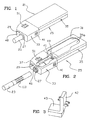
- a preferred embodiment of the present invention provides a photonic electronic smoking system 21 which includes a cigarette 23 preferably of a particular design and a reusable, electronic lighter 25 having a photonic heater fixture 37 into which a cigarette may be inserted at the receptacle 27 of the fixture 37.
- the smoking system 21 is used in much the same fashion as a more traditional cigarette, but without a lighting or continuous smoldering of the cigarette 23.
- the cigarette 23 is discarded after one or more puff cycles.
- the lighter 25 is configured to generate from each cigarette 23 a total of eight puffs (puff cycles) or more per smoke; however it is a matter design expedient to adjust to a lesser or a greater number of total available puffs.
- the lighter 25 includes a housing 31 which preferably can be disassembled into front and rear housing portions 33 and 35.
- One or more batteries 35a are removably located within the rear housing portion 35 for supplying power to photonic element(s) of the heater fixture 37 under the control and monitoring of a control circuit (“controller”) 41, which preferably is located in the front housing portion 33.
- the controller 41 operates to heater fixture 27 responsively to signals generated by a puff sensor 49.
- the controller 41 is responsive to a puff-actuated sensor 49 that is sensitive to either changes in pressure or changes in rate of air flow which occur upon initiation of a draw on the cigarette 23 by a smoker.
- the puff sensor 49 is preferably located within the front housing portion 33 of the lighter 25 and is communicated with a space inside the heater fixture 37 adjacent the cigarette 23 through a passageway extending through a spacer at the base of the heater fixture 37 and, if desired, a puff sensor tube (not shown).
- a puff sensor 49 suitable for use in the smoking system 21 is described in commonly assigned U.S. Patent No. 5,060,671 (PM 1337).
- the puff sensor 49 preferably comprises a Model 163PCO1D35 silicon sensor, manufactured by the MicroSwitch division of Honeywell, Inc., Freeport, Illinois. Flow sensing devices, such as those using hot-wire anemometry principles, have also been successfully demonstrated to be useful for actuating a heater fixture upon detection of a change in air flow.
- the controller 41 executes a predetermined power application cycle wherein power from the batteries 35a is directed to an operative element of the heater fixture 37.
- the rear portion 35 is adapted to be readily opened and closed, such as with screws or snap-fit components, to facilitate replacement of the batteries 35a.
- a recharge port 40 is provided at a convenient location along the housing 31 for establishing electrical connection with an exeternal source of power, such as ordinary house or automobile current.
- the recharge port 40 preferably is arranged to plug into a recharger fixture 42, which is itself is adapted to be plugged into a wall socket or other source of household (or automobile) current.
- the recharge port 40 can be arranged to plug directly into the source of external power.
- the front housing portion 33 is removably joined to the rear housing portion 35, such as with a dovetail joint or a socket fit.
- the housing 31 is preferably made from a hard, heat-resistant material. Preferred materials include metallic or, more preferably, polymeric materials.
- the housing 31 has overall dimensions such that it may fit comfortably in the hand of a smoker.
- the batteries 35a are sized to provide sufficient power for the heater fixture 37 to function as intended and preferably comprise a replaceable, rechargeable type.
- Alternate sources of power are suitable, such as capacitors.
- the power source comprises four nickel-cadmium battery cells connected in series with a total, non-loaded voltage of preferably, approximately 4.8 to 5.6 volts.
- the commonly assigned patent U.S. Patent No. 5,144,962 (PM 1345), describes several types of power sources useful in connection with the smoking system of the present invention, such as rechargeable battery sources and power arrangements which comprise a capacitor which is recharged by a battery.
- the same patent also provides pertinent teachings regarding recharger arrangements which operate with an electronic smoking article.
- the electronic lighter 25 includes a shutter 46 across the receptacle 27 to prevent the escape of errant photonic beams from the lasing heater fixture 37 in the absence of a cigarette 23.
- the shutter 46 is openable for the admission of a cigarette by manual operation of a detent lever 29.
- a spring 48 or some other biasing arrangement is provided within the housing 33 to bias the shutter 46 from its retracted position toward its operative, receptacle-closing position.
- the interior surfaces of the front housing portion 33 may be provided with a light absorbing coating.
- An indicator 51 is provided at a location along the exterior of the lighter 25, preferably on the front housing portion 33, to indicate the number of puffs remaining in a smoke of a cigarette 23.
- the indicator 51 preferably includes a seven-segment liquid crystal display. In the preferred embodiment, the indicator 51 displays the digit "8" when a cigarette is newly inserted into the heater fixture 37.
- the photonic-electronic smoking system 21 of the present invention is preferably practiced with cigarettes of designs particularly suited for the electronic lighter 23.
- These preferred designs and other constructions are more particularly set forth and described in commonly assigned U.S. Patent No. 5,499,636 (PM 1759B), which teaches the particulars of the partially filled, filler cigarette 23 of Fig. 4A; commonly assigned, co-pending U.S. application Serial No. No. 08/485/176, filed June 7, 1995 (PM 1731), which teaches a fully-filled cigarette 23' as shown in Fig. 4B; and U.S. Patent No. 5,388,594 (PM 1697), which teaches the particulars of a filler-free cigarette 23" of the like shown in Fig. 4C.
- the cigarettes shown in 4A-C include their having a tobacco rod portion 50 and a filter tipping portion 52, wherein the tobacco rod 50 is formed from a tubularly folded, tobacco mat 62.
- the tobacco rod portion 50 preferably includes a tubular plug 54 at a location adjacent the tipping 52 that defines a flow constriction 56 at the tipped end of the tobacco rod 50.
- the tipping 50 comprises a hollow "whistle-through" filter plug 58 and a low efficiency mouthpiece filter 59, which minimize filtering effect upon aerosol produced within the tobacco rod 50 during a puff cycle.
- the tobacco mat 62 preferably comprises a base web 64 and a layer of tobacco material 66 disposed along the base web 64.
- a layer of cigarette paper is wrapped about the longitudinal extent of the mat 62.
- the cigarette 23 of Fig. 4A includes a plug of tobacco 70 at the free end of the tobacco rod 50 and a void 72 at a location between the tobacco plug 70 and the tubular element 54.
- the tobacco plug 70 is resistive to the escape of aerosol from the free end 74 of the tobacco rod 50.
- both a portion of the tobacco plug 70 and a portion of the tobacco mat 62 are heated simultaneously during the execution of a puff cycle so each may contribute their own tobacco aromas and taste to the smoke drawn from the cigarette 23. Either component may be smoked individually if desired.
- the tobacco rod 50' is filled with tobacco (preferably a cut filler) along its entirety up to the tubular element 54'.
- a filter plug such as a plug constructed from cellulose acetate tow or creped paper, is situated at the free end 74" of the tobacco rod 50".
- a filter plug such as a plug constructed from cellulose acetate tow or creped paper
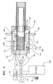
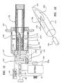
- a first preferred embodiment of an electronic lighter, 25 of the photonic-electronic smoking system 21 includes a receptacle 27 affixed at a convenient location along the housing 31, preferably along the front portion 33.
- An outer portion 80 of the receptacle 27 includes a kiss-seal portion 82 for slidingly receiving the cigarette 23 as the cigarette 23 is inserted and removed from the receptacle 27.
- the seal portion 82 also limits admission of air into the receptacle from about the periphery of the inserted cigarette 23.
- one or more ports 84 are provided adjacent the seal portion 82 for the controlled admission of air into the receptacle 27.
- air may be admitted through the front portion 33 of the housing 31 at one more ports 86 located in the housing 31 itself.
- the outer portion 80 of the receptacle 27 is threaded into or otherwise releasably engaged with the inner portion 90 of the receptacle 27 at a union 88 so that the outer portion 80 can be removed to facilitate cleaning and/or inspection of the contents within the inner portion 90 of the receptacle 27.
- an end cap 92 Fixedly secured to the opposite end of the receptacle 27 is an end cap 92 having an interior stop portion 98 which receives the free end 74 of the cigarette 23 when it is fully inserted into the receptacle 27. When so received, the tobacco rod 50 of the cigarette 23 occupies a spacial extent within the receptacle which is referenced as the cigarette-receiving space 100 of the receptacle 27.
- the end cap 92 includes a plurality of support arms 94, each which extends axially along the radially outward portion of the space enclosed by the receptacle of 27.
- the support arms 94 provide support to a plurality of photonic assemblies 96 in a predetermined spacial relation from the stop portion 98 of the cap 92 and from the cigarette receiving space 100 defined within the receptacle 27.
- opposing pairs of support arms 94 and 94' support a photonic assembly 96 such that the output of each photonic assembly 96 is directed radially inwardly toward a discrete location along the space 100.
- Each photonic assembly 96 preferably comprises a linear laser diode 102 and an associated lens element 104.
- the lens element 104 is arranged to focus and otherwise direct the output of the laser diode 102 to one of a plurality of locations about the cigarette receiving space 100, which corresponds to a desired region 110 along an inserted cigarette 23.
- the output of each laser diode 102 is sufficient to heat a respective region 110 of dimensions in the range of 0.5 millimeter (mm) to 4mm across and 2 mm to 20 mm in length, most preferably of approximately 2 mm by 14 mm.
- Each of the laser diodes 102 are electrically connected to the controller 41 by electrical leads 106 so that upon detection of a draw upon the cigarette 23 by the sensor 49, the controller provides electric power from the batteries 35a to a selected one of the laser diodes 102 in accordance with a predetermined power application cycle.
- the controller might be configured to initially read battery voltage so as to adjust the power delivered to the laser diode 102 or to adjust the duration of the power cycle or both.
- Such control techniques are detailed in the commonly assigned U.S. Patent No. 5,388,594 (PM 1697) and in the commonly assigned U.S. Patent No. 5,372,148.
- the controller 41 is configured to supply power to each of the photon emitting elements (laser diodes) 102 in accordance with first and second phases (and optionally a third) wherein the power delivered to the cigarette at the target region 110 is predetermined so as to optimize the production of tobacco aerosol and wherein the controller 41 dynamically adjusts the duty cycle in each phase of power application to the laser diode 102 so as to maintain the total power of each phase irregardless of real-time battery voltage and other factors.
- Such control techniques are detailed in the commonly assigned, copending U.S. application Serial No. 08/755044 filed on even date herewith.
- each laser diode 102 comprises a high powered, laser diode such as a quasi-continuous-wave, linear diode that is available from SLD Inc. of San Jose, California.
- each laser diode 102 is configured to deliver approximately 10 to 20 watts or more in a 5 to 10 micron wavelength.
- Each photonic assembly 96 preferably also includes an outer casing or seal 108 which in cooperation with the lens portion 104 prevents contact between the laser diode 102 and any lingering aerosol that may remain in the receptacle 27 after execution of a puff cycle.
- the photonic assembly 96 is located radially spaced from the cigarette 23 so as to provide for the admission of air at or about the region 110 heated by the photonic assembly 96 upon actuation of the latter during a puff cycle.
- This feature also facilitates withdrawal of the cigarette 23 from the receptacle 27 in that the heated regions 110 are not physically contacted by the heater fixture 37, except by the seal portion 82 at the outer portion 80 of the receptacle 27. With such physical contact minimized, the chances of the cigarette 23 being snagged and/or torn in the receptacle 27 are minimized.
- a source of photonic energy 112 (the plurality of circumferentially spaced laser diodes 102) and an optical train 114 comprising the plurality of circumferentially spaced lens elements 104 which are configured to direct the output of each laser diode 102 to a respective region 110 about the portion of the cigarette 23 occupying the space 100 of the receptacle 27.
- the length of axial displacement of the photonic assembling 96 relative to the stop surface 98 is preferably optimized with regard to the construction of the cigarette 23.
- the photonic elements 96 are preferably located so that upon their discharge, they heat a region 110 which partially overlaps the tobacco plug 70 and partially overlaps the void 72 in accordance with the teachings of commonly assigned U.S. Patent No. 5,499,636 (PM 1759B).
- the optical train 114 provides for each laser diode 102 optical direction so as to establish a heated region 110 of approximately 6-14 mm by 2 mm. With such cigarettes, it is preferred that the heated region be heated to temperatures sufficient to support the release of tobacco aerosol.
- the base portion 93 of the end cap 92 preferably also provides support to a cigarette detector 116, which photo-optically determines whether a cigarette 23 is located in the cigarette-receiving space 100 within the receptacle 27.
- the cigarette detector 116 is electrically connected with the controller 41.
- the cigarette detector 116 preferably comprises a light sensor at the base of the heater fixture 39 that detects when a beam of light is reflected off an inserted cigarette 23.
- the cigarette detector 116 provides a signal to the circuitry 41 which, in turn, responsively provides a signal to the indicator 51.
- the display of the digit "8" on the indicator 51 reflects that the eight puffs provided on each cigarette 23 are available, i.e., none of the photonic assemblies 96 have been actuated to heat the cigarette 23.
- the indicator displays the digit "0".
- the cigarette detector 116 no longer detects a presence of a cigarette 23 and the indicator 51 is turned off.
- the cigarette detector 116 is modulated so that it does not constantly emit a beam of light, which would otherwise create an unnecessary drain on the power source 35a.
- a preferred cigarette detector 116 suitable for use with the smoking system 21 is a Type OPR5005 Light Sensor, manufactured by OPTEX Technology, Inc., 1215 West Crosby Road, Carrollton, Texas 75006.
- the detector display may instead be arranged to indicate whether the system is active or inactive ( “on” or “off”) or in need of cleaning or recharging.
- a mechanical switch (not shown) may be provided to detect the presence or absence of a cigarette 23 and a reset button (not shown) may be provided for resetting the circuitry 41 when a new cigarette is inserted into the lighter 25, e.g., to cause the indicator 51 to display the digit "8", etc.
- Power sources, circuitry, puff-actuated sensors, and indicators useful with the smoking system 21 of the present invention are described in commonly assigned, U.S. Patent No. 5,060,671 (PM 1337) and the commonly assigned U.S. Patent No. 5,388,594 (PM 1697).
- the base portion 93 of the heater fixture 37 is provided with a stop 98 against which the cigarette 23 is urged during its placement into the lighter 25 so as to assure consistent placement of the various operative components of the heater fixture 37 relative to each cigarette 23 from cigarette to cigarette.
- the stop surface 98 may comprise a detent or the like which leaves the free end 74 of the cigarette 23 only partially covered and slightly spaced from the base element 98 so that air may be admitted into the cigarette from the uncovered portion of the end 74 of the cigarette 23.
- the base portion 93 of the receptacle end cap 92 preferably includes a port 101 for communicating the puff sensor 49 with the interior of the receptacle 27. Additionally, the end cap 92 may also includes one or more air channels 103 for the introduction of predetermined amounts of air into the receptacle at locations at or about the stop 98.
- the front housing portion 33 of the lighter 25 preferably encloses the electronic controller 41, which is operative to deliver a predetermined amount of energy from the power source 35a to operative elements of the heater fixture 37.
- an alternate arrangement for the electronic heater fixture 27 includes a source of photonic energy 112 comprising a plurality of photonic assemblies 96 as previously described (each itself comprising a laser diode 102 and a lens/aerosol barrier 104), together with a transmissive annulus interposed between the plurality of photonic assemblies 96 and the cigarette-receiving space 100 of the receptacle 27.
- the transmissive annulus 120 comprises alternating regions of optically configured portions 122 and cigarette contacting portions 124.
- the optical portions 122 have concave inner surfaces 123 which are spaced away from a cigarette 23 to create a longitudinal opening 126 along the received cigarette 23 for the admission of air at or about the regions 110 where the cigarette 23 is heated.
- the surfaces of the lens 104 and those of the optical portion 122 cooperate to focus the output of the laser diode 102 at the target region 110 along the cigarette 23.
- the cigarette contacting portions 124 of the annulus 120 slidingly received the tobacco rod 50 so as to assure a more consistent placement of the target region 110 relative to the photonic source 112 and optical train 114 of previous description.
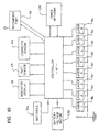
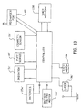
- the controller 41 of the smoking system 21 executes cooperative functionalities between the plurality of photonic assemblies 96 with the puff sensor 49, the indicator display 51, a timer network 130, a battery voltage monitor 132, and the batteries 35a.
- the controller 41 comprises an application specific integrated circuit or ASIC.
- ASIC application specific integrated circuit
- the controller 41 references the battery voltage monitor 132 during a puff cycle so as to execute real-time control of power application, such as by adjusting the pulse duration of each photonic assembly actuation dependently upon voltage level that is detected by the battery monitor 132. Once a puff cycle is complete, the indicator display 51 adjusted to reflect the remaining count of puffs now available from the cigarette 23.
- the smoking routine is not executed unless the cigarette sensor 116 has detected a presence of a cigarette 23 within the confines of the receptacle 27 as previously explained. Execution of a power application cycle is also refused by the controller 41 if it should detect battery voltage being below a specified minimum and/or if the controller 41 perceives that external power from the recharge port 40 is either available and/or being communicated with the batteries 35a (for recharging) or being communicated with the photonic assemblies 96 (for cleaning).
- the preferred source of radiative (photonic) energy in this embodiment and all other embodiments disclosed herein is a lasing source
- other photonic sources could be employed in the alternative.
- arrays of light emitting diodes or halogen or quartz lamps or other sources of broad banded, non-coherent, multi-chromatic radiation
- sources of photonic energy 112 throughout the embodiments instead of a laser.
- an alternate, preferred embodiment of the present invention includes an electronic lighter 25 and cigarette 23, the latter being of any of the types described in reference to Figs. 4A-C, although other types of cigarettes may be well suited for use with the alternate electronic lighter 25'.
- the cigarette 23 is slidingly received in the receptacle of 27' against a stop surface 98' of a base portion 93'.
- an air channel 103' may be provided in the base portion 93' of the base portion 93'.
- the puff sensor 49' communicates preferably through a port 101' in the base portion 93'.
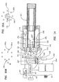
- the controller 41 communicates with a single source of photonic energy 112', preferably a laser diode, whose output is directed along a central light pipe 140 that extends through the base portion 93' of the receptacle 27' axially along the center line of the received cigarette 23.
- the light pipe 140 is encased by a rigid, rotatable tube 142 which at its free end supports an optical pointed tip 144.
- the opposite end of the tube 142 extends outside of the receptacle of 27' and is freely rotatable about the light pipe 140 by the action of a step motor 146 upon a turntable 147 through a geared drive connection 148.
- the tube 142, together with the optical tip 144 is progressed from one angular position to the next while the optical tip 144 also remains aligned with the optical pipe 140 so that the tip 144 receives the output of the photonic source 112' at each angular position.
- the optical tip 144 preferably includes a pointed, leading portion 150 for facilitating insertion of the tip 144 and the tube 144 through a longitudinal portion of the cigarette 23; a beam directing surface 152 for redirecting the output of the light pipe 140 from a generally longitudinal (axial) direction to one which includes a transverse component relative to the axis of the cigarette 23; and a light transmissive surface 154 which permits transmission of the redirected beam 158 from within the tip 144 toward a preselected region 110' of the cigarette 23.
- the light transmissive surface 156 is shown in Fig. 12 as a localized area, the light transmissive surface 155 may be annular and/or comprise the substantial entirety of the outer surface of the optical tip 144.
- the controller 41' In operation, once the cigarette detector 116' signals to the controller 41' that a cigarette is present in the receptacle 27' and upon the puff sensor 49' providing a signal to the controller 41' that drawing action is occurring upon the cigarette 23, the controller 41' effects a controlled application of power from the batteries 35a' to the photonic source 112' in a prescribed manner in accordance with a power application cycle as previously discussed.
- the step motor Upon completion of the first puff cycle, the step motor progresses to the next angular station, thereby rotating to tube 140 and the optical tip 144 to a corresponding second angular position relative to the receptacle 27' and the cigarette 23.
- a second, non-rotational outer tube may be provided about the rotatable tube 140 to isolate the rotational action of the tube 140 from the cigarette 23.
- the cigarette Upon completion of a smoke (usually at conclusion of all puff cycles), the cigarette is removed from the receptacle 27', which action effects some wiping action upon the transmissive surface 155 to help remove condensates and dirt therefrom.
- the receptacle 27' is now available for the insertion of a fresh cigarette which is urged to the stop surface 98' of the base portion 93' within the receptacle 27', thereby skewering the cigarette upon the tube 140.
- the controller 41' cooperates with the various elements as previously described with reference to Fig. 10, except that the controller 41' progresses from one puff cycle to the next by executing and monitoring the progression of the step motor 146 from one angular position to the next and executes a plurality of photonic discharges from the same photonic source 112', which discharge progresses through the optical train 114' comprising the light pipe 140 and the optical tip 144 as previously described.
- a second battery 150 is included within the lighter 25 to power the step motor 146 so as to dedicate the power potential of the main batteries 35a' to the execution of puff cycles.
- the optical tip 144 may be located within the tobacco plug 170 itself and/or other cut filler of the cigarettes having a design as discussed previously with reference to Figs. 4A and B so as to heat the cut filler directly and without the imposition of the cigarette wrapper.
- the tube 142 and tip 144 may remain angularly stationary so that the discharge of the photonic 112' during execution of the puff cycle fixedly heats the predetermined area 110'.
- the controller 41' and the step motor 146 are configured to controllably turn the optical tip 144 slightly during at least a portion of the puff cycle so that so that the optical tip 144 progresses through an angular position during each puff. Consequently, the situs of application of radiation upon the cigarette 23 progresses along the the target region 110, heating portions of it as the situs moves along.
- This capacity is hereafter referred to as spacial modulation of the heater output.
- the same effect can be achieved in a less convenient manner by moving other elements of the smoking system 21 during the course of a puff cycle, such as the cigarette 23, itself.
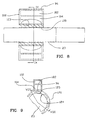
- another alternate embodiment of the present invention includes an electronic lighter 25", which includes a receptacle 27", wherein a plurality of (preferably eight) light pipes 155 extend axially through the base portion 93" of the receptacle cap 92".
- the various members of the light pipes 155 are preferably mutually parallel, axially directed and spaced circumferentially apart from one another, and radially spaced from the cigarette-receiving space 100 in the receptacle 27.
- Each light pipe 155 includes a first tip 156 located within the receptacle 27", each tip 156 including a reflective light directing surface 158 which directs the light progressing along the light pipe 155 from a substantially axial direction to one transverse to the axis of the receptacle 27" (or the received cigarette 23). Light is transmitted from the tip 156 toward the target region 110 along the exterior of the cigarette 23.
- the light pipes 155 extend through the base portion 93" of the receptacle cap 92" and terminate in a second set of optical tips 160 preferably outside of the receptacle 27".
- Each second optical tip 160 is configured to transmissively receive light that is directed in a radially outward direction and includes a light directing surface 161 to redirect the received light into an axial direction toward the first optical tip 156.
- a rotatable light distributor 162 which preferably comprises an optical pipe 164 that is optically arranged to receive the output of a single photonic source 112" and includes a mirrored end 165.
- the mirrored end 165 is rotatable upon a turntable 166, which in turn is driven from one angular position to the next by a step motor 168 and a drive link 170 between the turn table 166 and the step motor 168.
- the mirrored end 165 directs each discharge of the photonic source 112 in a radially outward direction at each predetermined angular location into a preselected one of the light pipes 155.
- the controller 41 From there the discharge is directed along the light pipe 155 and ultimately to the target region 110 along the cigarette 23.
- the controller 41" Upon the controller 41" receiving a signal indicative of a puff being drawn upon the cigarette 23, and with the cigarette sensor 116" having established the presence of a cigarette 23, the controller 41 actuates the photonic source 112" and photonic energy is transmitted along the optical train 114" (the light distributor 162 and the associated plurality of light pipes 155) as so described.
- the electronic lighter 25" of this alternate embodiment includes a plurality of the detectors that provide monitoring of photonic output from the photonic source 112" together with signals indicative of the cleanliness of the optical surfaces at the first optical tips 156.
- a photo-sensor 174 located adjacent the rotatable mirrored element 165 can be configured to receive a transmitted fraction of the photonic discharge, such as a .5% or less component of the beam entering the mirrored element 165.
- photo sensors 176 and 178 are also provided at or about the first optical tips 156 at locations where at they may receive light transmitted through the reflective surfaces 158 of the first tips 156 in much the same way as arranged at the rotatable mirrored element 165, and/or to receive re-emissions, either of which being indicative of a degree of cleanliness at optical surfaces.
- the light directing surface at the optical tip 156 may be given a 99.5% reflective efficiency, with the 0.5% transmitted component being directed toward a photo-sensor 178. If aerosol compensate should collect at/or about the tip 156, the transmission of light through the tips 156 would diminish and signals from the sensor 178 would change accordingly.
- another detector 176 is preferably placed across the array of first tips 156 so as to be in approximate alignment with the output from an opposing optical tip 156a. Accordingly, at a time when a cigarette 23 is absent from the receptacle 27", the controller 41" may include the functionality of pinging a signal through a particular, opposing light pipe 155a so that a beam of known initial quantity is directed toward the detector 176.
- the controller 41" is preferably configured to curtail execution of power application cycles for puff cycles, and instead readies the lighter 25 for a cleaning mode wherein power is applied from the recharge port 40" to the photonic source 112" according to a second, different cleaning power cycle.
- the heater fixture 37 may be cleaned manually.
- the controller 41 when the controller 41 receives a signal indicative that the optical train 114 needs cleaning or that the battery voltage has dropped below a predetermined minimum such that recharging is necessary, the controller 41 preferably establishes a signal at the indicator display 51, that either of both of those conditions exist and awaits for receipt of a signal from the recharge port 40 or other indication that external electrical power is available at the recharge port 40. During the interim, the controller 41 preferable places the electronic lighter 25 in a dormant condition so that it cannot be operated to smoke a cigarette 23 until after a recharging session or a cleaning session or both are undertaken as circumstances may require.
- the controller 41 In the execution of a cleaning session and when the controller 41 detects the availability of external power at the recharge port 40, the controller 41 preferably establishes a power application cycle to the photonic source 112 at a reduced duty cycle configured to volatilize condensates and thermally remove other matter collected at those portions of the optical train typically needing cleansing, i.e. portions of the lens/aerosol barrier 104 of the first embodiment, or the optical portions 122 of the annulus 120 described in reference Fig. 9, or the optical tip 144 of the second embodiment described with reference to Fig. 11 or the first tips 156 of the third embodiment described in reference to Fig. 14.
- the cleaning power application cycle preferably includes a ramping of power such that a low power application (a lower duty cycle) is applied first to remove the more volatile components of the compensate and dirt, followed by a higher power application (a higher duty cycle) for the less volatile components.
- the controller 41 also, or in the alternative, monitors the need for executing a cleaning cycle upon registering (counting) the number of cigarettes 23 that are inserted and withdrawn from the receptacle 27 as indicated by the output of the cigarette detector 116.
- the controller 41 is preferably operative to execute a recharging of the batteries 35a upon detection of the availability of external power at the recharge port 40. Recharging is undertaken until such time that the battery voltage monitor 132 provides a signal indicating that battery voltage has returned a desired, full-charged value.
- the rotatable light distributor 162 may remain angularly stationary so that the discharge of the photonic 112" during execution of the puff cycle fixedly heats the predetermined area 110".
- controller 41" and the step motor 146' are configured to controllably turn the rotatable light distributor 162 slightly during at least a portion of the puff cycle so that so that the rotatable light distributor 162 progresses through an angular position during each puff. Consequently, the situs of application of radiation upon the cigarette 23 progresses along the the target region 110", heating portions of it as the situs moves along so as to achieve spacial modulation of the heat applied to the cigarette as previously described.
- a fourth preferred embodiment of the present invention includes a single light pipe cylinder 155' having first and second rims 156' and 160', all which elements function in like manner to the plurality of light pipes 155 and the optical tips 156 and 160. More particularly, the first rim 156' of the light pipe cylinder 155' is located within the receptacle 27' and includes a photon directing surface 158' for redirecting radiation travelling axially along the interior of light pipe cylinder 155' from an axial direction to a radial direction toward the cigarette 23". The reflective surface 161' of the second rim 160' receives light from the light distributor 162'.
- the light pipe cylinder 155' provides greater latitude for the aiming and translation of the rotatable light distributor 162', particular when moving the rotatable light distributor 162' to effect spacial modulation.
- a modification to the first preferred embodiment to effect spacial modulation includes provision of a motor 200 in a controlled communication with the controller 41 and a drive connection to 210 between the motor 200 and the annulus 120.
- the controller 41 is operative to actuate the motor 200, which in turn causes the annulus 120 to angularly translate slightly during at least a portion of the puff cycle.
- the electronic lighter 25' as described with reference to Fig. 14 may include an annulus 120" interposed between the first optical tips 156 and the cigarette-receiving space 100".
- the annulus 120" preferably is constructed in accordance with the annulus 120 described in reference to Figs. 8 and 9, including the alternating optical and cigarette-contacting portions 122" and 124".
Abstract
Description
Claims (40)
- An electronic lighter (25) of an electrical smoking system, said electrical lighter comprising:a receptacle (27) for removably receiving a cigarette along a cigarette-receiving space defined by said receptacle;a photonic source (37);an optical train (114) establishing a plurality of optical pathways from said photonic source to a plurality of locations at said cigarette receiving space of said receptacle;a source of electrical power (35);a puff sensor (49) responsive to a drawing action upon a cigarette (23) received by said receptacle; anda controller (41) responsive to said puff sensor (49) for controllably communicating said source of electrical power (35) with said photonic source (37) so that upon drawing action upon the received cigarette, the photonic source discharges along said optical pathway to heat a region of said cigarette adjacent at least one of said locations.
- The electrical lighter of claim 1, wherein said photonic source (37) comprises a plurality of discrete photonic elements (102) and said optical train directs the discharge of each photonic element to at least one of said plurality of locations (110) at said receiving cigarette (23), said controller (41) operative to communicate said source of electrical power (35) with at least one but less than all of said photonic elements (102) responsively to a signal from said puff sensor (49).
- The lighter as claimed in claim 2, wherein said controller (41) communicates each of said plurality of photonic elements (102) in accordance with a predetermined sequence and in accordance with a first predetermined power application cycle.
- The lighter as claimed in claim 3 further comprising a cigarette detector (116) operative to generate a signal indicative of a presence of a cigarette (23) in said receptacle, said controller (41) disabled from executing said power application cycle in the absence of said cigarette indicative signal from said cigarette detector.
- The lighter as claimed in claim 4, wherein said power source comprises a battery (35a), a battery monitor (132) operative to generate a signal indicative of a voltage condition at said battery, said lighter further comprising a recharger port (40) for establishing connection with a source of power external of said lighter, said controller (41) operative to controllably communicate said recharger port (40) with said batteries (35a) responsively to a detection of a predetermined voltage condition at said battery from said battery monitor (132).
- The lighter of claim 5 further comprises a cleanliness sensor (174) operative to monitor a cleanliness condition at a location along said optical train, said controller being further operative to communicate said photonic source (37) with said recharger port (40) responsively to said controller (41) receiving a signal indicative of an availability of external power at said recharger port and a signal from said cleanliness sensor at a predetermined threshold.
- The lighter as claimed in claim 6, wherein said controller (41) is operative to communicate said battery (35a) with said photonic source (37) in accordance with a first power schedule, and further operative to communicate power received at said recharger port (40) to said photonic elements (102) in accordance with a second power application cycle; said second power cycle adapted to clean said location along said optical train.
- The lighter as in claim 6, further comprising a photo-sensor (178) optically arranged to receive an output from said location and in communication with said controller, said photo-sensor operative to provide said controller a signal indicative of a presence of condensate at said location along said optical train.
- The lighter as in claim 2, wherein each said photonic elements (102) comprise a laser diode.
- The lighter as claimed in claim 9, wherein said optical train (114) comprises a plurality of optical elements (104) optically arranged to cooperate with said laser diodes (102) said optical elements spaced from said cigarette receiving space.
- The lighter as claimed in claim 10, wherein said optical train (114) includes an annulus (120) interposed between said plurality of photonic elements (102) and said cigarette receiving space, said annulus (120) including discrete locations (112) operative as part of said optical pathway from each photonic element (102) to said location at said cigarette receiving space.
- The lighter as claimed in claim 11, wherein said annulus includes a plurality of second discrete portions (124) for contacting said cigarette so as to locate the adjacent portions of the received cigarette relative to said plurality of photonic of elements (102).
- The lighter of claim 5, further comprising a detachable recharger fixture (42) having a first electrical connection cooperative with said recharge port (40) and a second electrical connector for establishing connection to a household electrical socket.
- The lighter as claimed in claim 1, wherein said optical train (114) comprises a plurality of optical pipes (155), said optical pipes extending from a plurality of first pipe portions outside of said receptacle (27) to a plurality of second pipe portions within said receptacle, said second pipe portions operative to direct light towards said locations at said cigarette receiving space, said lighter further comprising a beam distributor (162) adapted to selectively direct said discharge of said photonic source (37) to said optical pipes (155) at said first pipe portions in accordance with a preselected sequence.
- The lighter as claimed in claim 14, wherein said beam distributor (162) comprises a rotatable optical element arranged to receive the output of said photonic source, said rotatable optical element rotatable into a plurality of angular positions, said rotatable optical element directing the discharge of said photonic source to different first portions of said plurality if optical pipes (155) at different angular positions.
- The lighter as claimed in claim 15, wherein said first portions of said plurality of optical pipes (155) are disposed radially about said rotatable optical element, said rotatable optical element (162) rotated by operation of a step drive, said controller operative to actuate said step drive (168) to rotate said rotatable optical element from one angular position to the next in accordance with said preselected sequence.
- The lighter as claimed in claim 16, wherein said step motor is powered by a battery.
- The lighter as claimed in claim 15, wherein said rotatable optical element comprises a partial mirror (165), said lighter further comprising a photonic power monitor comprising an optical detector (174) arranged to receive a transmitted fraction of said photonic discharge through said partial mirror, said reflected portion of said photonic discharge at said rotatable optical element (155) being directed toward said first portions of said plurality of optical pipes, said photonic power monitor in communication with said controller.
- The lighter as claimed in claim 14, further comprising a condensate monitor (178) comprising a photo detector (178) at a location adjacent at least on of said second portions of said optical pipes, said condensate monitor in communication with said controller (41) said condensate monitor operative to generate a signal indicative of level of condensate at said second portion, said controller being further operative to place said lighter in a dormant mode upon receiving a signal from said condensate monitor indicative that the condensate exceeds a predetermined threshold.
- The lighter as claimed in claim 18 or 19, wherein said second portion of said optical pipe includes a partial mirror (158), a reflected majority of said photonic discharge being directed by said partial mirror (158) toward said location along said received cigarette space, at least a portion of said photonic discharge being transmissible through said partial mirror toward said condensate monitor (178).
- The lighter as claimed in claim 14, wherein said optical train (114) further comprises an annulus (120) adjacent said second portions of said light pipes, said annulus including discrete locations (122) operative as part of said optical pathway from each of said second portions to each location at said cigarette receiving space, said annulus including a plurality of second discrete portions (124) for consistency positioning the received cigarette relative to said optical train.
- The lighter as claimed in claim 21 further comprising a cigarette detector (116) operative to detect the presence of a cigarette in said receptacle.
- The lighter as claimed in claim 22, wherein said power source comprises a battery (35a) a battery monitor (132) operative to generate a signal indicative of a voltage condition at said battery, said lighter further comprising a recharger port (40) for establishing connection with a source of power external of said lighter, said controller (41) operative to controllably communicate said recharger port (40) with said batteries responsively to a detection of a predetermined voltage condition at said battery by said battery monitor.
- The lighter as claimed in claim 14, wherein said controller (41) is further operative to controllably communicate said photonic source (37) with said external power source (350 at said recharger port (40) responsively to said signal from said condensate monitor.
- The lighter as claimed in claim 24, wherein said controller is operative to communicate said battery (35a) with said photonic source (37) in accordance with a first power application cycle, and further operative to communicate external power received at said recharger port (40) to said photonic source in accordance with a second power schedule, said first power schedule adapted to promote heating of the received cigarette; said second power schedule adapted to clean a selected portion of said optical train.
- The lighter of claim 24, further comprising a detachable recharger fixture (42) having a first electrical connection cooperative with said recharge port and a second electrical connector for establishing connection to a household electrical socket.
- The lighter as claimed in claim 1, wherein said optical train comprises an optical pipe (140) extending axially into said cigarette receiving space of said receptacle, and a rotatable beam director (142, 144) arranged to direct output of said light pipe (140) from an axial direction to a transverse direction, said optical train further comprising a drive for controllably rotating said beam director sequentially amongst a plurality of angular positions, responsively to said controller, so that upon sequential rotation of said beam director, said photonic discharge is directed amongst said plurality of locations at said cigarette receiving space.
- The lighter as claimed in claim 27, wherein said rotatable beam director (142, 144) is rotated by operation of a step monitor, (146) said controller operative to actuate said step motor to rotate said rotatable optical element from one angular position to the next in accordance with said sequence.
- The lighter as claimed in claim 28, wherein said step monitor is powered by a battery.
- The lighter as claimed in claim 29, further comprising a condensate detector comprising a photo detector at a location adjacent at least a second end portion of the optical pipe, said condensate detector in communication with said controller, said controller further operative to monitor condensate along said optical train responsively to said condensate detector.
- The lighter as claimed in claim 30 further comprising a cigarette detector (116) operative to detect the presence of a cigarette in said receptacle and in communication with said cigarette detector.
- The lighter as claimed in claim 24 or 31, wherein said power source comprises a battery (35a), a battery monitor (135) operative to generate a signal indicative of a voltage condition at said battery, said lighter further comprising a recharger port (40) for establishing connection with a source of power external of said lighter, said controller operative to controllably communicate said recharger port with said batteries responsively to a detection of a predetermined voltage condition at said battery by said battery monitor.
- The lighter as claimed in claim 24, wherein said controller (41) is operative to communicate said battery with said photonic source (37) in accordance with a first power application cycle, and further operative to communicate external power received at said recharger port to said photonic source in accordance with a second power schedule, said first power schedule adapted to promote heating of the received cigarette; said second power schedule adapted to clean a selected portion of said optical train.
- The lighter of claim 33, further comprising a detachable recharger fixture (42) having a first electrical connector cooperative with said recharge port and a second electrical connector for establishing connection to a household electrical socket.
- The lighter as claimed in claim 1, wherein said optical train (114) comprises a cylindrical optical pipe (140) said optical pipe extending from a first pipe portion outside of said receptacle to a second pipe portion within said receptacle, said second pipe portion operative to direct light toward said locations at said cigarette receiving space, said lighter further comprising a beam distributor (142) adapted selectively to direct said discharge of said photonic source to said optical pipe at said first pipe in accordance with a preselected sequence.
- The lighter as claimed in claim 35, wherein said beam distributor comprises (142) a rotatable optical element (144) arranged to receive the output of said photonic source, said rotatable element rotatable into a plurality of angular positions, said rotatable optical element directing the discharge of said photonic source to different angular locations along said first portion of said optical pipe.
- The lighter as claimed in claim 36, wherein said first portion of said optical pipe (140) is disposed radially about said rotatable optical element (142), said rotatable optical element rotated by operation of a step drive (146) said controller operative to actuate said step drive to rotate said rotatable optical element from one angular position to the next in accordance with said preselected sequence.
- The lighter as claimed in claims 1, 11, 27 or 35, wherein the controller (41) is operative to effect displacement of an element of the optical train (114) during at least a portion of the execution of a puff cycle so as to move said photonic discharge along a predetermined target region of the inserted cigarette.
- A method of smoking a cigarette comprising the steps of:inserting a cigarette into a receptacle of a lighter;repetitively generating a photonic beam from a photonic source of the lighter responsively to each puff sensed by a puff sensor of a predetermined number of puffs wherein the lighter includes an optical train establishing a plurality of optical pathways from the photonic source;directing, under the control of a controller, each of said generated photonic beams along one of the optical pathways to respective, different locations about said inserted cigarette from puff to puff in response to the puff sensor, the controller communicating the photonic source with a source of electrical power, so that during each puff upon the inserted cigarette, a tobacco aerosol is thermally generated at a discrete location at the cigarette by a photonic beam.
- The method as claimed in claim 39 wherein said step of repetitively generating a photonic beam responsively to each puff includes the step of generating a photonic discharge repetitively from a single source, and said step of directing each of said generated photonic beams to respective, different locations about said inserted cigarette from puff to puff includes the step of directing said photonic discharge to a rotatable light deflector and rotating said light deflector from one predetermined angular position to the next from puff to puff.
Applications Claiming Priority (5)
| Application Number | Priority Date | Filing Date | Title |
|---|---|---|---|
| US73505196A | 1996-10-22 | 1996-10-22 | |
| US735051 | 1996-10-22 | ||
| US954752 | 1997-10-20 | ||
| US08/954,752 US5934289A (en) | 1996-10-22 | 1997-10-20 | Electronic smoking system |
| PCT/US1997/018493 WO1998017130A1 (en) | 1996-10-22 | 1997-10-21 | Electronic smoking system |
Publications (2)
| Publication Number | Publication Date |
|---|---|
| EP0951219A1 EP0951219A1 (en) | 1999-10-27 |
| EP0951219B1 true EP0951219B1 (en) | 2002-11-13 |
Family
ID=27112829
Family Applications (1)
| Application Number | Title | Priority Date | Filing Date |
|---|---|---|---|
| EP97910933A Expired - Lifetime EP0951219B1 (en) | 1996-10-22 | 1997-10-21 | Electronic smoking system |
Country Status (9)
| Country | Link |
|---|---|
| US (1) | US5934289A (en) |
| EP (1) | EP0951219B1 (en) |
| JP (1) | JP2002514910A (en) |
| AT (1) | ATE227524T1 (en) |
| AU (1) | AU734913B2 (en) |
| CA (1) | CA2269496A1 (en) |
| DE (1) | DE69717149D1 (en) |
| HK (1) | HK1020253A1 (en) |
| WO (1) | WO1998017130A1 (en) |
Cited By (9)
| Publication number | Priority date | Publication date | Assignee | Title |
|---|---|---|---|---|
| US8375957B2 (en) | 2006-05-16 | 2013-02-19 | Ruyan Investment (Holdings) Limited | Electronic cigarette |
| US8393331B2 (en) | 2004-04-14 | 2013-03-12 | Ruyan Investment (Holdings) Limited | Electronic atomization cigarette |
| US8511318B2 (en) | 2003-04-29 | 2013-08-20 | Ruyan Investment (Holdings) Limited | Electronic cigarette |
| US8689805B2 (en) | 2009-02-11 | 2014-04-08 | Fontem Holdings 1 B.V. | Electronic cigarette |
| CN103859595A (en) * | 2014-04-02 | 2014-06-18 | 川渝中烟工业有限责任公司 | Sliding cover type heating and sucking device of cigarette free of combustion in heating process |
| US10034988B2 (en) | 2012-11-28 | 2018-07-31 | Fontem Holdings I B.V. | Methods and devices for compound delivery |
| CN109068745A (en) * | 2016-04-29 | 2018-12-21 | 英美烟草(投资)有限公司 | Method for generating the article and heating smokeable material of inhalable medium |
| US10194693B2 (en) | 2013-09-20 | 2019-02-05 | Fontem Holdings 1 B.V. | Aerosol generating device |
| EP4133955A4 (en) * | 2021-03-29 | 2023-12-06 | KT&G Corporation | Laser-based aerosol generating device and heating control method therefor |
Families Citing this family (464)
| Publication number | Priority date | Publication date | Assignee | Title |
|---|---|---|---|---|
| USD433532S (en) * | 1998-10-09 | 2000-11-07 | Philip Morris Incorporated | Hand-held smoking unit |
| US6196218B1 (en) * | 1999-02-24 | 2001-03-06 | Ponwell Enterprises Ltd | Piezo inhaler |
| USD424373S (en) * | 1999-03-31 | 2000-05-09 | Ronson Corporation | Igniter |
| US7266767B2 (en) * | 2000-11-27 | 2007-09-04 | Parker Philip M | Method and apparatus for automated authoring and marketing |
| US20030072717A1 (en) * | 2001-02-23 | 2003-04-17 | Vapotronics, Inc. | Inhalation device having an optimized air flow path |
| AU2002310054B2 (en) * | 2001-05-21 | 2007-02-01 | Injet Digital Aerosols Limited | Compositions for protein delivery via the pulmonary route |
| US20030051728A1 (en) | 2001-06-05 | 2003-03-20 | Lloyd Peter M. | Method and device for delivering a physiologically active compound |
| US7458374B2 (en) | 2002-05-13 | 2008-12-02 | Alexza Pharmaceuticals, Inc. | Method and apparatus for vaporizing a compound |
| US7645442B2 (en) | 2001-05-24 | 2010-01-12 | Alexza Pharmaceuticals, Inc. | Rapid-heating drug delivery article and method of use |
| US20070122353A1 (en) | 2001-05-24 | 2007-05-31 | Hale Ron L | Drug condensation aerosols and kits |
| US20040025895A1 (en) * | 2001-08-31 | 2004-02-12 | Ping Li | Oxidant/catalyst nanoparticles to reduce tobacco smoke constituents such as carbon monoxide |
| US7011096B2 (en) * | 2001-08-31 | 2006-03-14 | Philip Morris Usa Inc. | Oxidant/catalyst nanoparticles to reduce carbon monoxide in the mainstream smoke of a cigarette |
| US6817365B2 (en) * | 2001-11-15 | 2004-11-16 | Philip Morris Usa Inc. | Cigarette paper having heat-degradable filler particles, and cigarette comprising a cigarette paper wrapper having heat-degradable filler particles |
| US6615840B1 (en) | 2002-02-15 | 2003-09-09 | Philip Morris Incorporated | Electrical smoking system and method |
| US6769437B2 (en) * | 2002-04-08 | 2004-08-03 | Philip Morris Incorporated | Use of oxyhydroxide compounds for reducing carbon monoxide in the mainstream smoke of a cigarette |
| EA005980B1 (en) * | 2002-04-12 | 2005-08-25 | Филип Моррис Продактс С.А. | Partially reduced nanoparticle additives for reducing the amount of carbon monoxide and/or nitric oxide present in mainstream smoke |
| US6803545B2 (en) * | 2002-06-05 | 2004-10-12 | Philip Morris Incorporated | Electrically heated smoking system and methods for supplying electrical power from a lithium ion power source |
| US20040016436A1 (en) * | 2002-07-26 | 2004-01-29 | Charles Thomas | Adsorbents for smoking articles comprising a non-volatile organic compound applied using a supercritical fluid |
| US6782892B2 (en) * | 2002-08-30 | 2004-08-31 | Philip Morris Usa Inc. | Manganese oxide mixtures in nanoparticle form to lower the amount of carbon monoxide and/or nitric oxide in the mainstream smoke of a cigarette |
| US6810883B2 (en) * | 2002-11-08 | 2004-11-02 | Philip Morris Usa Inc. | Electrically heated cigarette smoking system with internal manifolding for puff detection |
| US7913688B2 (en) * | 2002-11-27 | 2011-03-29 | Alexza Pharmaceuticals, Inc. | Inhalation device for producing a drug aerosol |
| US7082825B2 (en) * | 2002-12-27 | 2006-08-01 | Yamatake Corporation | Smoking device including a flowmeter |
| US8012399B2 (en) * | 2003-03-07 | 2011-09-06 | Philip Morris Usa Inc. | Formation of nano-or micro-scale phenolic fibers via electrospinning |
| US7370657B2 (en) * | 2003-04-02 | 2008-05-13 | Philip Morris Usa Inc. | Activated carbon-containing sorbent |
| US6814786B1 (en) | 2003-04-02 | 2004-11-09 | Philip Morris Usa Inc. | Filters including segmented monolithic sorbent for gas-phase filtration |
| ES2370395T3 (en) | 2003-05-21 | 2011-12-15 | Alexza Pharmaceuticals, Inc. | USE OF A SOLID FUEL LAYER, MANUFACTURING PROCEDURE AND CORRESPONDING HEATING UNIT. |
| US7004993B2 (en) * | 2003-06-13 | 2006-02-28 | Philip Morris Usa Inc. | Nanoscale particles of iron aluminide and iron aluminum carbide by the reduction of iron salts |
| US7243658B2 (en) * | 2003-06-13 | 2007-07-17 | Philip Morris Usa Inc. | Nanoscale composite catalyst to reduce carbon monoxide in the mainstream smoke of a cigarette |
| JP4637099B2 (en) * | 2003-06-13 | 2011-02-23 | フィリップ・モーリス・プロダクツ・ソシエテ・アノニム | Cigarette wrapper with catalyst filler and method of making the same |
| US7165553B2 (en) * | 2003-06-13 | 2007-01-23 | Philip Morris Usa Inc. | Nanoscale catalyst particles/aluminosilicate to reduce carbon monoxide in the mainstream smoke of a cigarette |
| US7152609B2 (en) * | 2003-06-13 | 2006-12-26 | Philip Morris Usa Inc. | Catalyst to reduce carbon monoxide and nitric oxide from the mainstream smoke of a cigarette |
| US9107452B2 (en) * | 2003-06-13 | 2015-08-18 | Philip Morris Usa Inc. | Catalyst to reduce carbon monoxide in the mainstream smoke of a cigarette |
| US7293565B2 (en) * | 2003-06-30 | 2007-11-13 | Philip Morris Usa Inc. | Electrically heated cigarette smoking system |
| US7028694B2 (en) * | 2003-08-22 | 2006-04-18 | Philip Morris Usa Inc. | Method for dispersing powder materials in a cigarette rod |
| US7392809B2 (en) * | 2003-08-28 | 2008-07-01 | Philip Morris Usa Inc. | Electrically heated cigarette smoking system lighter cartridge dryer |
| US20060032510A1 (en) * | 2003-10-27 | 2006-02-16 | Philip Morris Usa Inc. | In situ synthesis of composite nanoscale particles |
| US8051859B2 (en) | 2003-10-27 | 2011-11-08 | Philip Morris Usa Inc. | Formation and deposition of sputtered nanoscale particles in cigarette manufacture |
| US7950400B2 (en) | 2003-10-27 | 2011-05-31 | Philip Morris Usa Inc. | Tobacco cut filler including metal oxide supported particles |
| US7712471B2 (en) * | 2003-10-27 | 2010-05-11 | Philip Morris Usa Inc. | Methods for forming transition metal oxide clusters and smoking articles comprising transition metal oxide clusters |
| US8701681B2 (en) * | 2003-10-27 | 2014-04-22 | Philip Morris Usa Inc. | Use of oxyhydroxide compounds in cigarette paper for reducing carbon monoxide in the mainstream smoke of a cigarette |
| US7509961B2 (en) * | 2003-10-27 | 2009-03-31 | Philip Morris Usa Inc. | Cigarettes and cigarette components containing nanostructured fibril materials |
| US8006703B2 (en) | 2003-10-27 | 2011-08-30 | Philip Morris Usa Inc. | In situ synthesis of composite nanoscale particles |
| US7677254B2 (en) * | 2003-10-27 | 2010-03-16 | Philip Morris Usa Inc. | Reduction of carbon monoxide and nitric oxide in smoking articles using iron oxynitride |
| US20050166935A1 (en) * | 2003-10-27 | 2005-08-04 | Philip Morris Usa Inc. | Reduction of carbon monoxide in smoking articles using transition metal oxide clusters |
| US20050133049A1 (en) * | 2003-12-22 | 2005-06-23 | Philip Morris Usa Inc. | Smoking articles and filters including zeolite molecular sieve sorbent |
| US7610920B2 (en) * | 2003-12-22 | 2009-11-03 | Philip Morris Usa Inc. | Thiol-functionalized sorbent for smoking articles and filters for the removal of heavy metals from mainstream smoke |
| US8439047B2 (en) * | 2003-12-22 | 2013-05-14 | Philip Morris Usa Inc. | Composite mesoporous/microporous materials and their use in smoking articles for removing certain gas phase constituents from tobacco smoke |
| US7540286B2 (en) | 2004-06-03 | 2009-06-02 | Alexza Pharmaceuticals, Inc. | Multiple dose condensation aerosol devices and methods of forming condensation aerosols |
| US7743772B2 (en) * | 2004-06-16 | 2010-06-29 | Philip Morris Usa Inc. | Silver and silver oxide catalysts for the oxidation of carbon monoxide in cigarette smoke |
| US7879128B2 (en) * | 2004-10-25 | 2011-02-01 | Philip Morris Usa Inc. | Palladium-containing nanoscale catalysts |
| US20060090769A1 (en) * | 2004-11-02 | 2006-05-04 | Philip Morris Usa Inc. | Temperature sensitive powder for enhanced flavor delivery in smoking articles |
| US20060185687A1 (en) * | 2004-12-22 | 2006-08-24 | Philip Morris Usa Inc. | Filter cigarette and method of making filter cigarette for an electrical smoking system |
| US8408216B2 (en) * | 2004-12-22 | 2013-04-02 | Philip Morris Usa Inc. | Flavor carrier for use in smoking articles |
| US20060144410A1 (en) | 2004-12-30 | 2006-07-06 | Philip Morris Usa Inc. | Surface-modified activated carbon in smoking articles |
| US8539957B2 (en) * | 2005-01-14 | 2013-09-24 | Philip Morris Usa Inc. | Cigarettes and cigarette filters including activated carbon for removing nitric oxide |
| US7578298B2 (en) | 2005-02-04 | 2009-08-25 | Philip Morris Usa Inc. | Flavor capsule for enhanced flavor delivery in cigarettes |
| US7878211B2 (en) * | 2005-02-04 | 2011-02-01 | Philip Morris Usa Inc. | Tobacco powder supported catalyst particles |
| US7622421B2 (en) * | 2005-03-11 | 2009-11-24 | Philip Morris Usa Inc. | Catalysts for low temperature oxidation of carbon monoxide |
| US7744846B2 (en) * | 2005-03-11 | 2010-06-29 | Philip Morris Usa Inc. | Method for forming activated copper oxide catalysts |
| US7503960B2 (en) * | 2005-03-15 | 2009-03-17 | Philip Morris Usa Inc. | Smoking articles and filters with carbon fiber composite molecular sieve sorbent |
| US7878209B2 (en) * | 2005-04-13 | 2011-02-01 | Philip Morris Usa Inc. | Thermally insulative smoking article filter components |
| US7878962B2 (en) | 2005-05-03 | 2011-02-01 | Philip Morris Usa Inc. | Cigarettes and filter subassemblies with squeezable flavor capsule and methods of manufacture |
| US9648907B2 (en) * | 2005-05-31 | 2017-05-16 | Philip Morris Usa Inc. | Virtual reality smoking system |
| US20160345631A1 (en) | 2005-07-19 | 2016-12-01 | James Monsees | Portable devices for generating an inhalable vapor |
| US9675109B2 (en) * | 2005-07-19 | 2017-06-13 | J. T. International Sa | Method and system for vaporization of a substance |
| US20070215167A1 (en) | 2006-03-16 | 2007-09-20 | Evon Llewellyn Crooks | Smoking article |
| US10188140B2 (en) | 2005-08-01 | 2019-01-29 | R.J. Reynolds Tobacco Company | Smoking article |
| US7791002B2 (en) * | 2005-08-22 | 2010-09-07 | Eveready Battery Company, Inc. | Battery powered cigarette lighter and process for using the same |
| US20070074734A1 (en) * | 2005-09-30 | 2007-04-05 | Philip Morris Usa Inc. | Smokeless cigarette system |
| US9491971B2 (en) * | 2005-12-13 | 2016-11-15 | Philip Morris Usa Inc. | Specifically-defined smoking article with activated carbon sorbent and sodium bicarbonate-treated fibers and method of treating mainstream smoke |
| US8118035B2 (en) | 2005-12-13 | 2012-02-21 | Philip Morris Usa Inc. | Supports catalyst for the combustion of carbon monoxide formed during smoking |
| US20070258879A1 (en) * | 2005-12-13 | 2007-11-08 | Philip Morris Usa Inc. | Carbon beads with multimodal pore size distribution |
| US8578943B2 (en) | 2005-12-20 | 2013-11-12 | Philip Morris Usa Inc. | Metal-containing nanowires prepared using mesoporous molecular sieves as templates, and their use in smoking articles for removing certain gas phase constituents from tobacco smoke |
| SI2077731T1 (en) * | 2006-01-17 | 2011-10-28 | Philip Morris Prod | Cigarette components having encapsulated catalyst particles and methods of making and use thereof |
| US7569510B2 (en) * | 2006-02-27 | 2009-08-04 | Philip Morris Usa Inc. | Catalysts to reduce carbon monoxide such as in the mainstream smoke of a cigarette |
| US9220301B2 (en) | 2006-03-16 | 2015-12-29 | R.J. Reynolds Tobacco Company | Smoking article |
| UA92214C2 (en) * | 2006-03-31 | 2010-10-11 | Филип Моррис Продактс С.А. | Filter element, a cigarette, comprising thereof, and a method for making the filter element |
| US9255361B2 (en) * | 2006-03-31 | 2016-02-09 | Philip Morris Usa Inc. | In situ formation of catalytic cigarette paper |
| US20070235049A1 (en) * | 2006-03-31 | 2007-10-11 | Philip Morris Usa Inc. | Magnetic filter elements and cigarettes having magnetic filter elements |
| US7726320B2 (en) | 2006-10-18 | 2010-06-01 | R. J. Reynolds Tobacco Company | Tobacco-containing smoking article |
| WO2008112661A2 (en) | 2007-03-09 | 2008-09-18 | Alexza Pharmaceuticals, Inc. | Heating unit for use in a drug delivery device |
| EP1989946A1 (en) * | 2007-05-11 | 2008-11-12 | Rauchless Inc. | Smoking device, charging means and method of using it |
| US8991402B2 (en) | 2007-12-18 | 2015-03-31 | Pax Labs, Inc. | Aerosol devices and methods for inhaling a substance and uses thereof |
| EP2100525A1 (en) * | 2008-03-14 | 2009-09-16 | Philip Morris Products S.A. | Electrically heated aerosol generating system and method |
| EP2110033A1 (en) | 2008-03-25 | 2009-10-21 | Philip Morris Products S.A. | Method for controlling the formation of smoke constituents in an electrical aerosol generating system |
| EP2110034A1 (en) | 2008-04-17 | 2009-10-21 | Philip Morris Products S.A. | An electrically heated smoking system |
| EP2201850A1 (en) | 2008-12-24 | 2010-06-30 | Philip Morris Products S.A. | An article including identification information for use in an electrically heated smoking system |
| EP2412396B2 (en) † | 2009-03-23 | 2023-10-18 | Japan Tobacco, Inc. | Non-combustion article for flavor inhalation |
| EP2253233A1 (en) | 2009-05-21 | 2010-11-24 | Philip Morris Products S.A. | An electrically heated smoking system |
| US10420374B2 (en) | 2009-09-18 | 2019-09-24 | Altria Client Services Llc | Electronic smoke apparatus |
| US8534294B2 (en) | 2009-10-09 | 2013-09-17 | Philip Morris Usa Inc. | Method for manufacture of smoking article filter assembly including electrostatically charged fiber |
| EP2327318A1 (en) | 2009-11-27 | 2011-06-01 | Philip Morris Products S.A. | An electrically heated smoking system with internal or external heater |
| WO2011112218A1 (en) * | 2010-03-12 | 2011-09-15 | Xiao Pei Tao | A system and method for providing a laser-based lighting system for smokable material |
| US8671951B2 (en) * | 2010-03-26 | 2014-03-18 | Philip Morris Usa Inc. | Methods of manufacturing cigarettes and filter subassemblies with squeezable flavor capsule |
| US20120017926A1 (en) | 2010-03-26 | 2012-01-26 | Philip Morris Usa Inc. | Cigarettes and filter subassemblies with squeezable oval flavor capsule and methods of manufacture |
| WO2011137453A2 (en) | 2010-04-30 | 2011-11-03 | Blec, Llc | Electronic smoking device |
| US9743691B2 (en) | 2010-05-15 | 2017-08-29 | Rai Strategic Holdings, Inc. | Vaporizer configuration, control, and reporting |
| US10159278B2 (en) | 2010-05-15 | 2018-12-25 | Rai Strategic Holdings, Inc. | Assembly directed airflow |
| US9095175B2 (en) | 2010-05-15 | 2015-08-04 | R. J. Reynolds Tobacco Company | Data logging personal vaporizing inhaler |
| US11344683B2 (en) | 2010-05-15 | 2022-05-31 | Rai Strategic Holdings, Inc. | Vaporizer related systems, methods, and apparatus |
| US9259035B2 (en) | 2010-05-15 | 2016-02-16 | R. J. Reynolds Tobacco Company | Solderless personal vaporizing inhaler |
| US9999250B2 (en) | 2010-05-15 | 2018-06-19 | Rai Strategic Holdings, Inc. | Vaporizer related systems, methods, and apparatus |
| US10136672B2 (en) | 2010-05-15 | 2018-11-27 | Rai Strategic Holdings, Inc. | Solderless directly written heating elements |
| US9861772B2 (en) | 2010-05-15 | 2018-01-09 | Rai Strategic Holdings, Inc. | Personal vaporizing inhaler cartridge |
| US8757147B2 (en) | 2010-05-15 | 2014-06-24 | Minusa Holdings Llc | Personal vaporizing inhaler with internal light source |
| DK3508083T3 (en) * | 2010-08-24 | 2021-10-11 | Jt Int Sa | INHALATION DEVICE INCLUDING SUBSTANCE USE CONTROL |
| EP2670024B1 (en) * | 2011-01-28 | 2018-08-22 | Huizhou Kimree Technology Co., Ltd. Shenzhen Branch | Wireless charging device |
| US9078473B2 (en) | 2011-08-09 | 2015-07-14 | R.J. Reynolds Tobacco Company | Smoking articles and use thereof for yielding inhalation materials |
| SG2014013627A (en) | 2011-08-16 | 2014-07-30 | Ploom Inc | Low temperature electronic vaporization device and methods |
| US9999247B2 (en) * | 2011-10-25 | 2018-06-19 | Philip Morris Products S.A. | Aerosol generating device with heater assembly |
| AR089602A1 (en) | 2011-12-30 | 2014-09-03 | Philip Morris Products Sa | AEROSOL GENERATOR ARTICLE FOR USE WITH AN AEROSOL GENERATOR DEVICE |
| DK2797450T3 (en) | 2011-12-30 | 2017-12-11 | Philip Morris Products Sa | SMOKING ARTICLE WITH FRONT PLUG AND METHOD |
| TWI589234B (en) * | 2012-01-03 | 2017-07-01 | 菲利浦莫里斯製品股份有限公司 | Polygonal aerosol-generating device and system |
| SG11201403830WA (en) * | 2012-01-03 | 2014-10-30 | Philip Morris Products Sa | Power supply system for portable aerosol-generating device |
| US9282772B2 (en) | 2012-01-31 | 2016-03-15 | Altria Client Services Llc | Electronic vaping device |
| US20130255702A1 (en) | 2012-03-28 | 2013-10-03 | R.J. Reynolds Tobacco Company | Smoking article incorporating a conductive substrate |
| GB2502053B (en) * | 2012-05-14 | 2014-09-24 | Nicoventures Holdings Ltd | Electronic smoking device |
| GB2502055A (en) | 2012-05-14 | 2013-11-20 | Nicoventures Holdings Ltd | Modular electronic smoking device |
| HUE029589T2 (en) | 2012-05-31 | 2017-03-28 | Philip Morris Products Sa | Flavoured rods for use in aerosol-generating articles |
| AR091509A1 (en) | 2012-06-21 | 2015-02-11 | Philip Morris Products Sa | ARTICLE TO SMOKE TO BE USED WITH AN INTERNAL HEATING ELEMENT |
| US10004259B2 (en) | 2012-06-28 | 2018-06-26 | Rai Strategic Holdings, Inc. | Reservoir and heater system for controllable delivery of multiple aerosolizable materials in an electronic smoking article |
| US10517530B2 (en) | 2012-08-28 | 2019-12-31 | Juul Labs, Inc. | Methods and devices for delivering and monitoring of tobacco, nicotine, or other substances |
| US8881737B2 (en) | 2012-09-04 | 2014-11-11 | R.J. Reynolds Tobacco Company | Electronic smoking article comprising one or more microheaters |
| US8910639B2 (en) | 2012-09-05 | 2014-12-16 | R. J. Reynolds Tobacco Company | Single-use connector and cartridge for a smoking article and related method |
| US9854841B2 (en) | 2012-10-08 | 2018-01-02 | Rai Strategic Holdings, Inc. | Electronic smoking article and associated method |
| US10117460B2 (en) | 2012-10-08 | 2018-11-06 | Rai Strategic Holdings, Inc. | Electronic smoking article and associated method |
| GB2507104A (en) | 2012-10-19 | 2014-04-23 | Nicoventures Holdings Ltd | Electronic inhalation device |
| US9210738B2 (en) | 2012-12-07 | 2015-12-08 | R.J. Reynolds Tobacco Company | Apparatus and method for winding a substantially continuous heating element about a substantially continuous wick |
| US8910640B2 (en) | 2013-01-30 | 2014-12-16 | R.J. Reynolds Tobacco Company | Wick suitable for use in an electronic smoking article |
| US10031183B2 (en) | 2013-03-07 | 2018-07-24 | Rai Strategic Holdings, Inc. | Spent cartridge detection method and system for an electronic smoking article |
| US20140261486A1 (en) | 2013-03-12 | 2014-09-18 | R.J. Reynolds Tobacco Company | Electronic smoking article having a vapor-enhancing apparatus and associated method |
| US9277770B2 (en) | 2013-03-14 | 2016-03-08 | R. J. Reynolds Tobacco Company | Atomizer for an aerosol delivery device formed from a continuously extending wire and related input, cartridge, and method |
| JP6426142B2 (en) | 2013-03-14 | 2018-11-21 | アール・ジエイ・レイノルズ・タバコ・カンパニー | Atomizer for aerosol dispensing device and related manufacturing materials, aerosol generating assembly, cartridge and method |
| US9918495B2 (en) | 2014-02-28 | 2018-03-20 | Rai Strategic Holdings, Inc. | Atomizer for an aerosol delivery device and related input, aerosol production assembly, cartridge, and method |
| US20140261487A1 (en) | 2013-03-14 | 2014-09-18 | R. J. Reynolds Tobacco Company | Electronic smoking article with improved storage and transport of aerosol precursor compositions |
| EP4018859A1 (en) | 2013-03-15 | 2022-06-29 | RAI Strategic Holdings, Inc. | Heating elements formed from a sheet of a material, inputs and methods for the production of atomizers, cartridge for an aerosol delivery device and method for assembling a cartridge for a smoking article |
| US9491974B2 (en) | 2013-03-15 | 2016-11-15 | Rai Strategic Holdings, Inc. | Heating elements formed from a sheet of a material and inputs and methods for the production of atomizers |
| US10279934B2 (en) | 2013-03-15 | 2019-05-07 | Juul Labs, Inc. | Fillable vaporizer cartridge and method of filling |
| US9423152B2 (en) | 2013-03-15 | 2016-08-23 | R. J. Reynolds Tobacco Company | Heating control arrangement for an electronic smoking article and associated system and method |
| US9220302B2 (en) | 2013-03-15 | 2015-12-29 | R.J. Reynolds Tobacco Company | Cartridge for an aerosol delivery device and method for assembling a cartridge for a smoking article |
| US9609893B2 (en) | 2013-03-15 | 2017-04-04 | Rai Strategic Holdings, Inc. | Cartridge and control body of an aerosol delivery device including anti-rotation mechanism and related method |
| IL297399B2 (en) | 2013-05-06 | 2024-02-01 | Juul Labs Inc | Nicotine salt formulations for aerosol devices and methods thereof |
| WO2014201432A1 (en) | 2013-06-14 | 2014-12-18 | Ploom, Inc. | Multiple heating elements with separate vaporizable materials in an electric vaporization device |
| USD745213S1 (en) * | 2013-07-12 | 2015-12-08 | Yariv Alima | Combined electric lighter and vaporizer |
| US11229239B2 (en) | 2013-07-19 | 2022-01-25 | Rai Strategic Holdings, Inc. | Electronic smoking article with haptic feedback |
| CN103416852B (en) * | 2013-08-02 | 2016-09-28 | 湖北中烟工业有限责任公司 | The cigarette smoking system of luminous energy heating Medicated cigarette |
| USD743099S1 (en) * | 2013-08-15 | 2015-11-10 | Ciarán Peter Oglesby | Vaporizer |
| US10172387B2 (en) | 2013-08-28 | 2019-01-08 | Rai Strategic Holdings, Inc. | Carbon conductive substrate for electronic smoking article |
| US9806549B2 (en) | 2013-10-04 | 2017-10-31 | Rai Strategic Holdings, Inc. | Accessory for an aerosol delivery device and related method and computer program product |
| US10292424B2 (en) | 2013-10-31 | 2019-05-21 | Rai Strategic Holdings, Inc. | Aerosol delivery device including a pressure-based aerosol delivery mechanism |
| US20150128969A1 (en) | 2013-11-11 | 2015-05-14 | R.J. Reynolds Tobacco Company | Mouthpiece for smoking article |
| US20150128968A1 (en) | 2013-11-11 | 2015-05-14 | R.J. Reynolds Tobacco Company | Mouthpiece for smoking article |
| CN104643290A (en) * | 2013-11-19 | 2015-05-27 | 王彦宸 | Laser atomization device |
| US9839237B2 (en) | 2013-11-22 | 2017-12-12 | Rai Strategic Holdings, Inc. | Reservoir housing for an electronic smoking article |
| SG10201901015YA (en) | 2013-12-03 | 2019-03-28 | Philip Morris Products Sa | Aerosol-generating article and electrically operated system incorporating a taggant |
| EP3076805A4 (en) | 2013-12-05 | 2017-10-11 | PAX Labs, Inc. | Nicotine liquid formulations for aerosol devices and methods thereof |
| USD825102S1 (en) | 2016-07-28 | 2018-08-07 | Juul Labs, Inc. | Vaporizer device with cartridge |
| PT3086671T (en) | 2013-12-23 | 2019-01-23 | Juul Labs Uk Holdco Ltd | Vaporization device systems |
| US10058129B2 (en) | 2013-12-23 | 2018-08-28 | Juul Labs, Inc. | Vaporization device systems and methods |
| US10159282B2 (en) | 2013-12-23 | 2018-12-25 | Juul Labs, Inc. | Cartridge for use with a vaporizer device |
| US9549573B2 (en) | 2013-12-23 | 2017-01-24 | Pax Labs, Inc. | Vaporization device systems and methods |
| US10076139B2 (en) | 2013-12-23 | 2018-09-18 | Juul Labs, Inc. | Vaporizer apparatus |
| USD842536S1 (en) | 2016-07-28 | 2019-03-05 | Juul Labs, Inc. | Vaporizer cartridge |
| US20160366947A1 (en) | 2013-12-23 | 2016-12-22 | James Monsees | Vaporizer apparatus |
| US9974334B2 (en) | 2014-01-17 | 2018-05-22 | Rai Strategic Holdings, Inc. | Electronic smoking article with improved storage of aerosol precursor compositions |
| US10575558B2 (en) | 2014-02-03 | 2020-03-03 | Rai Strategic Holdings, Inc. | Aerosol delivery device comprising multiple outer bodies and related assembly method |
| US9451791B2 (en) | 2014-02-05 | 2016-09-27 | Rai Strategic Holdings, Inc. | Aerosol delivery device with an illuminated outer surface and related method |
| US20150224268A1 (en) | 2014-02-07 | 2015-08-13 | R.J. Reynolds Tobacco Company | Charging Accessory Device for an Aerosol Delivery Device and Related System, Method, Apparatus, and Computer Program Product for Providing Interactive Services for Aerosol Delivery Devices |
| US9833019B2 (en) | 2014-02-13 | 2017-12-05 | Rai Strategic Holdings, Inc. | Method for assembling a cartridge for a smoking article |
| US9839238B2 (en) | 2014-02-28 | 2017-12-12 | Rai Strategic Holdings, Inc. | Control body for an electronic smoking article |
| PL2915443T3 (en) * | 2014-03-03 | 2020-01-31 | Fontem Holdings 1 B.V. | Electronic smoking device |
| US9597466B2 (en) | 2014-03-12 | 2017-03-21 | R. J. Reynolds Tobacco Company | Aerosol delivery system and related method, apparatus, and computer program product for providing control information to an aerosol delivery device via a cartridge |
| US11696604B2 (en) | 2014-03-13 | 2023-07-11 | Rai Strategic Holdings, Inc. | Aerosol delivery device and related method and computer program product for controlling an aerosol delivery device based on input characteristics |
| GB2524735B (en) | 2014-03-31 | 2017-10-25 | Nicoventures Holdings Ltd | Re-charging pack for an e-cigarette |
| GB2524736B (en) | 2014-03-31 | 2021-02-24 | Nicoventures Holdings Ltd | Re-charging pack for an e-cigarette |
| USD775762S1 (en) * | 2014-03-31 | 2017-01-03 | Smiss Technology Co., Ltd | Electronic smoke device |
| WO2016012795A1 (en) * | 2014-07-24 | 2016-01-28 | Nicoventures Holdings Limited | Re-charging pack for an e-cigarette |
| US9877510B2 (en) | 2014-04-04 | 2018-01-30 | Rai Strategic Holdings, Inc. | Sensor for an aerosol delivery device |
| DK3132545T3 (en) * | 2014-04-14 | 2018-10-08 | Philip Morris Products Sa | POWER AND DATA TRANSMISSION SYSTEM AND PROCEDURE |
| JP1517979S (en) * | 2014-04-17 | 2015-02-23 | ||
| TWI681691B (en) | 2014-04-30 | 2020-01-01 | 瑞士商菲利浦莫里斯製品股份有限公司 | Electrically heated aerosol-generating system, device and method of controlling the same |
| US20150313282A1 (en) | 2014-05-01 | 2015-11-05 | R.J. Reynolds Tobacco Company | Electronic smoking article |
| US9924741B2 (en) | 2014-05-05 | 2018-03-27 | Rai Strategic Holdings, Inc. | Method of preparing an aerosol delivery device |
| WO2015175568A1 (en) | 2014-05-12 | 2015-11-19 | Loto Labs, Inc. | Improved vaporizer device |
| US11478021B2 (en) | 2014-05-16 | 2022-10-25 | Juul Labs, Inc. | Systems and methods for aerosolizing a vaporizable material |
| US20150335070A1 (en) | 2014-05-20 | 2015-11-26 | R.J. Reynolds Tobacco Company | Electrically-powered aerosol delivery system |
| US9955726B2 (en) | 2014-05-23 | 2018-05-01 | Rai Strategic Holdings, Inc. | Sealed cartridge for an aerosol delivery device and related assembly method |
| US10888119B2 (en) | 2014-07-10 | 2021-01-12 | Rai Strategic Holdings, Inc. | System and related methods, apparatuses, and computer program products for controlling operation of a device based on a read request |
| US10058123B2 (en) | 2014-07-11 | 2018-08-28 | R. J. Reynolds Tobacco Company | Heater for an aerosol delivery device and methods of formation thereof |
| CA160775S (en) | 2014-08-11 | 2015-09-29 | Ploom Inc | Electronic vaporization device with cartridge |
| EP3182846B1 (en) * | 2014-08-21 | 2021-03-17 | Philip Morris Products S.a.s. | Aerosol-generating device and system |
| US9913493B2 (en) | 2014-08-21 | 2018-03-13 | Rai Strategic Holdings, Inc. | Aerosol delivery device including a moveable cartridge and related assembly method |
| US10765144B2 (en) | 2014-08-21 | 2020-09-08 | Rai Strategic Holdings, Inc. | Aerosol delivery device including a moveable cartridge and related assembly method |
| US9609895B2 (en) | 2014-08-21 | 2017-04-04 | Rai Strategic Holdings, Inc. | System and related methods, apparatuses, and computer program products for testing components of an aerosol delivery device |
| GB2534336A (en) * | 2014-09-26 | 2016-07-27 | Kind Consumer Ltd | A method of assembling and testing a simulated cigarette |
| US11051554B2 (en) | 2014-11-12 | 2021-07-06 | Rai Strategic Holdings, Inc. | MEMS-based sensor for an aerosol delivery device |
| CN112155255A (en) | 2014-12-05 | 2021-01-01 | 尤尔实验室有限公司 | Corrective dose control |
| US10500600B2 (en) | 2014-12-09 | 2019-12-10 | Rai Strategic Holdings, Inc. | Gesture recognition user interface for an aerosol delivery device |
| US10398175B2 (en) | 2014-12-11 | 2019-09-03 | Philip Morris Products S.A. | Inhaling device with user recognition based on inhalation behaviour |
| GB201501429D0 (en) * | 2015-01-28 | 2015-03-11 | British American Tobacco Co | Apparatus for heating aerosol generating material |
| US10321711B2 (en) | 2015-01-29 | 2019-06-18 | Rai Strategic Holdings, Inc. | Proximity detection for an aerosol delivery device |
| USD775414S1 (en) * | 2015-02-19 | 2016-12-27 | Rai Strategic Holdings, Inc. | Charge and carry case |
| AU2016257164B2 (en) * | 2015-02-25 | 2020-09-17 | Lumenary Inc. | Handheld apparatus for vaporization of plant-based or synthetic compounds by laser |
| AU364985S (en) * | 2015-03-03 | 2015-10-29 | Beyond Twenty Ltd | Cartridge for an electronic cigarette case |
| US10027016B2 (en) | 2015-03-04 | 2018-07-17 | Rai Strategic Holdings Inc. | Antenna for an aerosol delivery device |
| US9980516B2 (en) | 2015-03-09 | 2018-05-29 | Rai Strategic Holdings, Inc. | Aerosol delivery device including a wave guide and related method |
| US10172388B2 (en) | 2015-03-10 | 2019-01-08 | Rai Strategic Holdings, Inc. | Aerosol delivery device with microfluidic delivery component |
| USD770678S1 (en) * | 2015-03-27 | 2016-11-01 | Jong-Soo Shin | Electronic cigarette |
| US11000069B2 (en) | 2015-05-15 | 2021-05-11 | Rai Strategic Holdings, Inc. | Aerosol delivery device and methods of formation thereof |
| GB201508405D0 (en) | 2015-05-15 | 2015-07-01 | British American Tobacco Co | Article and apparatus for generating an aerosol |
| US10238145B2 (en) | 2015-05-19 | 2019-03-26 | Rai Strategic Holdings, Inc. | Assembly substation for assembling a cartridge for a smoking article |
| US10226073B2 (en) | 2015-06-09 | 2019-03-12 | Rai Strategic Holdings, Inc. | Electronic smoking article including a heating apparatus implementing a solid aerosol generating source, and associated apparatus and method |
| CN104983073A (en) * | 2015-07-07 | 2015-10-21 | 深圳市赛尔美电子科技有限公司 | Cigarette distilling device |
| US11504489B2 (en) | 2015-07-17 | 2022-11-22 | Rai Strategic Holdings, Inc. | Contained liquid system for refilling aerosol delivery devices |
| US10966460B2 (en) | 2015-07-17 | 2021-04-06 | Rai Strategic Holdings, Inc. | Load-based detection of an aerosol delivery device in an assembled arrangement |
| US10206429B2 (en) * | 2015-07-24 | 2019-02-19 | Rai Strategic Holdings, Inc. | Aerosol delivery device with radiant heating |
| US11033054B2 (en) | 2015-07-24 | 2021-06-15 | Rai Strategic Holdings, Inc. | Radio-frequency identification (RFID) authentication system for aerosol delivery devices |
| US10015987B2 (en) | 2015-07-24 | 2018-07-10 | Rai Strategic Holdings Inc. | Trigger-based wireless broadcasting for aerosol delivery devices |
| US11134544B2 (en) * | 2015-07-24 | 2021-09-28 | Rai Strategic Holdings, Inc. | Aerosol delivery device with radiant heating |
| USD768331S1 (en) * | 2015-07-24 | 2016-10-04 | Shenzhen Smiss Technology Co., Ltd | Electronic cigarette |
| USD785862S1 (en) * | 2015-08-21 | 2017-05-02 | Shenzhen Jieshibo Technology Co., Ltd. | Electronic cigarette |
| USD785237S1 (en) * | 2015-08-21 | 2017-04-25 | Shenzhen Jieshibo Technology Co., Ltd. | Electronic cigarette |
| US10034494B2 (en) | 2015-09-15 | 2018-07-31 | Rai Strategic Holdings, Inc. | Reservoir for aerosol delivery devices |
| US10058125B2 (en) | 2015-10-13 | 2018-08-28 | Rai Strategic Holdings, Inc. | Method for assembling an aerosol delivery device |
| EP3155909B1 (en) * | 2015-10-16 | 2018-03-21 | Fontem Holdings 1 B.V. | Slide-on attachment for electronic smoking devices |
| US10918134B2 (en) | 2015-10-21 | 2021-02-16 | Rai Strategic Holdings, Inc. | Power supply for an aerosol delivery device |
| US20170112194A1 (en) | 2015-10-21 | 2017-04-27 | Rai Strategic Holdings, Inc. | Rechargeable lithium-ion capacitor for an aerosol delivery device |
| US10582726B2 (en) | 2015-10-21 | 2020-03-10 | Rai Strategic Holdings, Inc. | Induction charging for an aerosol delivery device |
| US20170119052A1 (en) * | 2015-10-30 | 2017-05-04 | R.J. Reynolds Tobacco Company | Application specific integrated circuit (asic) for an aerosol delivery device |
| US10201187B2 (en) | 2015-11-02 | 2019-02-12 | Rai Strategic Holdings, Inc. | User interface for an aerosol delivery device |
| USD769520S1 (en) * | 2015-11-04 | 2016-10-18 | Feel Life Inc | E-cigarette battery |
| US10820630B2 (en) | 2015-11-06 | 2020-11-03 | Rai Strategic Holdings, Inc. | Aerosol delivery device including a wirelessly-heated atomizer and related method |
| EP4059365B1 (en) | 2015-11-24 | 2023-11-08 | R. J. Reynolds Tobacco Company | Electrically-powered aerosol delivery system |
| US10440992B2 (en) | 2015-12-07 | 2019-10-15 | Rai Strategic Holdings, Inc. | Motion sensing for an aerosol delivery device |
| US9955733B2 (en) | 2015-12-07 | 2018-05-01 | Rai Strategic Holdings, Inc. | Camera for an aerosol delivery device |
| US11291252B2 (en) | 2015-12-18 | 2022-04-05 | Rai Strategic Holdings, Inc. | Proximity sensing for an aerosol delivery device |
| US10092036B2 (en) | 2015-12-28 | 2018-10-09 | Rai Strategic Holdings, Inc. | Aerosol delivery device including a housing and a coupler |
| US10051891B2 (en) | 2016-01-05 | 2018-08-21 | Rai Strategic Holdings, Inc. | Capacitive sensing input device for an aerosol delivery device |
| US10194694B2 (en) | 2016-01-05 | 2019-02-05 | Rai Strategic Holdings, Inc. | Aerosol delivery device with improved fluid transport |
| US10258086B2 (en) | 2016-01-12 | 2019-04-16 | Rai Strategic Holdings, Inc. | Hall effect current sensor for an aerosol delivery device |
| US10104912B2 (en) | 2016-01-20 | 2018-10-23 | Rai Strategic Holdings, Inc. | Control for an induction-based aerosol delivery device |
| USD771867S1 (en) * | 2016-01-21 | 2016-11-15 | The Hand Media, Inc | Personal vaporizer |
| US10015989B2 (en) | 2016-01-27 | 2018-07-10 | Rai Strategic Holdings, Inc. | One-way valve for refilling an aerosol delivery device |
| MX2018009702A (en) | 2016-02-11 | 2019-07-08 | Juul Labs Inc | Fillable vaporizer cartridge and method of filling. |
| BR112018016402B1 (en) | 2016-02-11 | 2023-12-19 | Juul Labs, Inc | SECURELY FIXED CARTRIDGES FOR VAPORIZER DEVICES |
| US11412781B2 (en) | 2016-02-12 | 2022-08-16 | Rai Strategic Holdings, Inc. | Adapters for refilling an aerosol delivery device |
| US20170251724A1 (en) | 2016-03-04 | 2017-09-07 | Rai Strategic Holdings, Inc. | Flexible display for an aerosol delivery device |
| US9936733B2 (en) | 2016-03-09 | 2018-04-10 | Rai Strategic Holdings, Inc. | Accessory configured to charge an aerosol delivery device and related method |
| US10405582B2 (en) | 2016-03-10 | 2019-09-10 | Pax Labs, Inc. | Vaporization device with lip sensing |
| US10334880B2 (en) | 2016-03-25 | 2019-07-02 | Rai Strategic Holdings, Inc. | Aerosol delivery device including connector comprising extension and receptacle |
| US11207478B2 (en) | 2016-03-25 | 2021-12-28 | Rai Strategic Holdings, Inc. | Aerosol production assembly including surface with micro-pattern |
| US10945462B2 (en) | 2016-04-12 | 2021-03-16 | Rai Strategic Holdings, Inc. | Detachable power source for an aerosol delivery device |
| US10333339B2 (en) | 2016-04-12 | 2019-06-25 | Rai Strategic Holdings, Inc. | Charger for an aerosol delivery device |
| USD773114S1 (en) * | 2016-04-12 | 2016-11-29 | The Hand Media, Inc. | Personal vaporizer |
| WO2017184250A1 (en) | 2016-04-19 | 2017-10-26 | Altria Client Services Llc | Application of a flavorant particle in the filter of a smoking article for delivering flavor |
| US10028534B2 (en) | 2016-04-20 | 2018-07-24 | Rai Strategic Holdings, Inc. | Aerosol delivery device, and associated apparatus and method of formation thereof |
| GB201607474D0 (en) * | 2016-04-29 | 2016-06-15 | British American Tobacco Co | Article, apparatus and method of heating a smokable material |
| US10405579B2 (en) | 2016-04-29 | 2019-09-10 | Rai Strategic Holdings, Inc. | Methods for assembling a cartridge for an aerosol delivery device, and associated systems and apparatuses |
| US10179690B2 (en) | 2016-05-26 | 2019-01-15 | Rai Strategic Holdings, Inc. | Aerosol precursor composition mixing system for an aerosol delivery device |
| USD849996S1 (en) | 2016-06-16 | 2019-05-28 | Pax Labs, Inc. | Vaporizer cartridge |
| US10959458B2 (en) | 2016-06-20 | 2021-03-30 | Rai Strategic Holdings, Inc. | Aerosol delivery device including an electrical generator assembly |
| USD836541S1 (en) | 2016-06-23 | 2018-12-25 | Pax Labs, Inc. | Charging device |
| USD851830S1 (en) | 2016-06-23 | 2019-06-18 | Pax Labs, Inc. | Combined vaporizer tamp and pick tool |
| USD848057S1 (en) | 2016-06-23 | 2019-05-07 | Pax Labs, Inc. | Lid for a vaporizer |
| US10085485B2 (en) | 2016-07-06 | 2018-10-02 | Rai Strategic Holdings, Inc. | Aerosol delivery device with a reservoir housing and a vaporizer assembly |
| US10231485B2 (en) | 2016-07-08 | 2019-03-19 | Rai Strategic Holdings, Inc. | Radio frequency to direct current converter for an aerosol delivery device |
| US10463078B2 (en) | 2016-07-08 | 2019-11-05 | Rai Strategic Holdings, Inc. | Aerosol delivery device with condensing and non-condensing vaporization |
| US10405581B2 (en) | 2016-07-08 | 2019-09-10 | Rai Strategic Holdings, Inc. | Gas sensing for an aerosol delivery device |
| US10617151B2 (en) | 2016-07-21 | 2020-04-14 | Rai Strategic Holdings, Inc. | Aerosol delivery device with a liquid transport element comprising a porous monolith and related method |
| US10602775B2 (en) | 2016-07-21 | 2020-03-31 | Rai Strategic Holdings, Inc. | Aerosol delivery device with a unitary reservoir and liquid transport element comprising a porous monolith and related method |
| CN207040892U (en) * | 2016-07-23 | 2018-02-27 | 深圳市合元科技有限公司 | Baking formula smoking set |
| CA172147S (en) * | 2016-07-28 | 2017-05-29 | Nerudia Ltd | Bottle |
| USD824099S1 (en) * | 2016-07-28 | 2018-07-24 | Nerudia Limited | Dispenser for E-liquid |
| CA172143S (en) * | 2016-07-28 | 2017-05-29 | Nerudia Ltd | Bottle |
| USD824097S1 (en) * | 2016-07-28 | 2018-07-24 | Nerudia Limited | Dispenser for E-liquid |
| US11019847B2 (en) | 2016-07-28 | 2021-06-01 | Rai Strategic Holdings, Inc. | Aerosol delivery devices including a selector and related methods |
| CA172145S (en) * | 2016-07-28 | 2017-05-29 | Nerudia Ltd | Bottle |
| US10765146B2 (en) | 2016-08-08 | 2020-09-08 | Rai Strategic Holdings, Inc. | Boost converter for an aerosol delivery device |
| US20180070634A1 (en) | 2016-09-09 | 2018-03-15 | Rai Strategic Holdings, Inc. | Analog control component for an aerosol delivery device |
| US20180070633A1 (en) | 2016-09-09 | 2018-03-15 | Rai Strategic Holdings, Inc. | Power source for an aerosol delivery device |
| US11937647B2 (en) | 2016-09-09 | 2024-03-26 | Rai Strategic Holdings, Inc. | Fluidic control for an aerosol delivery device |
| EP3512364B1 (en) | 2016-09-14 | 2021-11-03 | Philip Morris Products S.A. | Aerosol-generating system and method for controlling the same |
| US11660403B2 (en) | 2016-09-22 | 2023-05-30 | Juul Labs, Inc. | Leak-resistant vaporizer device |
| US10080387B2 (en) | 2016-09-23 | 2018-09-25 | Rai Strategic Holdings, Inc. | Aerosol delivery device with replaceable wick and heater assembly |
| US10477896B2 (en) | 2016-10-12 | 2019-11-19 | Rai Strategic Holdings, Inc. | Photodetector for measuring aerosol precursor composition in an aerosol delivery device |
| US20180132526A1 (en) | 2016-11-11 | 2018-05-17 | Rai Strategic Holdings, Inc. | Real-time temperature control for an aerosol delivery device |
| US20180132528A1 (en) | 2016-11-14 | 2018-05-17 | Rai Strategic Holdings, Inc. | Photoelectric proximity sensor for gesture-based control of an aerosol delivery device |
| US20180132529A1 (en) | 2016-11-14 | 2018-05-17 | Rai Strategic Holdings, Inc. | Aerosol delivery device with integrated wireless connectivity for temperature monitoring |
| US10492530B2 (en) | 2016-11-15 | 2019-12-03 | Rai Strategic Holdings, Inc. | Two-wire authentication system for an aerosol delivery device |
| US10524508B2 (en) | 2016-11-15 | 2020-01-07 | Rai Strategic Holdings, Inc. | Induction-based aerosol delivery device |
| US9864947B1 (en) | 2016-11-15 | 2018-01-09 | Rai Strategic Holdings, Inc. | Near field communication for a tobacco-based article or package therefor |
| US11103012B2 (en) | 2016-11-17 | 2021-08-31 | Rai Strategic Holdings, Inc. | Satellite navigation for an aerosol delivery device |
| US10653183B2 (en) | 2016-11-18 | 2020-05-19 | Rai Strategic Holdings, Inc. | Power source for an aerosol delivery device |
| US10524509B2 (en) | 2016-11-18 | 2020-01-07 | Rai Strategic Holdings, Inc. | Pressure sensing for an aerosol delivery device |
| US10172392B2 (en) | 2016-11-18 | 2019-01-08 | Rai Strategic Holdings, Inc. | Humidity sensing for an aerosol delivery device |
| US10206431B2 (en) | 2016-11-18 | 2019-02-19 | Rai Strategic Holdings, Inc. | Charger for an aerosol delivery device |
| US10537137B2 (en) | 2016-11-22 | 2020-01-21 | Rai Strategic Holdings, Inc. | Rechargeable lithium-ion battery for an aerosol delivery device |
| RU2753552C2 (en) | 2016-12-01 | 2021-08-17 | Раи Стретеджик Холдингс, Инк. | Rechargeable lithium-ion capacitor for aerosol delivery device |
| EP3549235B1 (en) | 2016-12-02 | 2021-05-05 | RAI Strategic Holdings, Inc. | Induction charging for an aerosol delivery device |
| US11013266B2 (en) | 2016-12-09 | 2021-05-25 | Rai Strategic Holdings, Inc. | Aerosol delivery device sensory system including an infrared sensor and related method |
| US10842188B2 (en) | 2016-12-14 | 2020-11-24 | Rai Strategic Holdings, Inc. | Smoking article for selective delivery of an aerosol precursor composition, a cartridge, and a related method |
| US10092039B2 (en) | 2016-12-14 | 2018-10-09 | Rai Strategic Holdings, Inc. | Smoking article for on-demand delivery of an increased quantity of an aerosol precursor composition, a cartridge, and a related method |
| US10366641B2 (en) | 2016-12-21 | 2019-07-30 | R.J. Reynolds Tobacco Company | Product display systems and related methods |
| JP6953554B2 (en) * | 2017-01-03 | 2021-10-27 | フィリップ・モーリス・プロダクツ・ソシエテ・アノニム | Charging station for electrically heated aerosol generators |
| US10080388B2 (en) | 2017-01-25 | 2018-09-25 | Rai Strategic Holdings, Inc. | Aerosol delivery device including a shape-memory alloy and a related method |
| US10517326B2 (en) | 2017-01-27 | 2019-12-31 | Rai Strategic Holdings, Inc. | Secondary battery for an aerosol delivery device |
| US10827783B2 (en) | 2017-02-27 | 2020-11-10 | Rai Strategic Holdings, Inc. | Digital compass for an aerosol delivery device |
| USD808073S1 (en) * | 2017-03-07 | 2018-01-16 | The Hand Media, Inc. | Personal vaporizer |
| US10219544B2 (en) | 2017-03-24 | 2019-03-05 | Rai Strategic Holdings, Inc. | Aerosol delivery device and a related method |
| US10674765B2 (en) | 2017-03-29 | 2020-06-09 | Rai Strategic Holdings, Inc. | Aerosol delivery device with improved atomizer |
| US10440995B2 (en) | 2017-03-29 | 2019-10-15 | Rai Strategic Holdings, Inc. | Aerosol delivery device including substrate with improved absorbency properties |
| USD799746S1 (en) * | 2017-04-06 | 2017-10-10 | The Hand Media, Inc. | Personal vaporizer |
| JP6974822B2 (en) * | 2017-04-11 | 2021-12-01 | 暮らし創研株式会社 | Smoking equipment |
| US10314340B2 (en) | 2017-04-21 | 2019-06-11 | Rai Strategic Holdings, Inc. | Refillable aerosol delivery device and related method |
| US10285444B2 (en) | 2017-04-27 | 2019-05-14 | Rai Strategic Holdings, Inc. | Aerosol delivery device including a ceramic wicking element |
| US11297876B2 (en) | 2017-05-17 | 2022-04-12 | Rai Strategic Holdings, Inc. | Aerosol delivery device |
| US11589621B2 (en) | 2017-05-23 | 2023-02-28 | Rai Strategic Holdings, Inc. | Heart rate monitor for an aerosol delivery device |
| US10517330B2 (en) | 2017-05-23 | 2019-12-31 | RAI Stategic Holdings, Inc. | Heart rate monitor for an aerosol delivery device |
| US10383369B2 (en) | 2017-06-07 | 2019-08-20 | Rai Strategic Holdings, Inc. | Fibrous filtration material for electronic smoking article |
| US11490653B2 (en) | 2017-06-23 | 2022-11-08 | Altria Client Services Llc | Smoking article |
| US10575562B2 (en) | 2017-06-30 | 2020-03-03 | Rai Strategic Holdings, Inc. | Smoking article for identifying an attribute of an aerosol-generating element for adaptive power output and an associated method |
| US10842197B2 (en) | 2017-07-12 | 2020-11-24 | Rai Strategic Holdings, Inc. | Detachable container for aerosol delivery having pierceable membrane |
| US11337456B2 (en) | 2017-07-17 | 2022-05-24 | Rai Strategic Holdings, Inc. | Video analytics camera system for an aerosol delivery device |
| US10349674B2 (en) | 2017-07-17 | 2019-07-16 | Rai Strategic Holdings, Inc. | No-heat, no-burn smoking article |
| KR20190049391A (en) | 2017-10-30 | 2019-05-09 | 주식회사 케이티앤지 | Aerosol generating apparatus having heater |
| BR112020002501A2 (en) | 2017-08-09 | 2020-08-04 | Philip Morris Products S.A. | aerosol generating device with modular induction heater |
| US10791761B2 (en) | 2017-08-17 | 2020-10-06 | Rai Strategic Holdings, Inc. | Microtextured liquid transport element for aerosol delivery device |
| US10561175B2 (en) * | 2017-08-22 | 2020-02-18 | Healthier Choices Management Corp. | Electronic vaporizer with laser heat source |
| CN207560362U (en) | 2017-09-01 | 2018-06-29 | 常州市派腾电子技术服务有限公司 | Voltage follower circuit and atomization plant |
| USD887632S1 (en) | 2017-09-14 | 2020-06-16 | Pax Labs, Inc. | Vaporizer cartridge |
| US10765143B2 (en) | 2017-09-14 | 2020-09-08 | Altria Client Services Llc | Smoking article with reduced tobacco |
| US10667554B2 (en) | 2017-09-18 | 2020-06-02 | Rai Strategic Holdings, Inc. | Smoking articles |
| US10505383B2 (en) | 2017-09-19 | 2019-12-10 | Rai Strategic Holdings, Inc. | Intelligent charger for an aerosol delivery device |
| US11039645B2 (en) | 2017-09-19 | 2021-06-22 | Rai Strategic Holdings, Inc. | Differential pressure sensor for an aerosol delivery device |
| US10157265B1 (en) | 2017-09-21 | 2018-12-18 | Rai Strategic Holdings, Inc. | Clinical study product dispensing device |
| US10660370B2 (en) | 2017-10-12 | 2020-05-26 | Rai Strategic Holdings, Inc. | Aerosol delivery device including a control body, an atomizer body, and a cartridge and related methods |
| US20190116863A1 (en) | 2017-10-24 | 2019-04-25 | Rai Strategic Holdings, Inc. | Method for formulating aerosol precursor for aerosol delivery device |
| KR102180421B1 (en) | 2017-10-30 | 2020-11-18 | 주식회사 케이티앤지 | Apparatus for generating aerosols |
| RU2738546C2 (en) | 2017-10-30 | 2020-12-14 | Кейтиэндджи Корпорейшн | Device for aerosol generation and method of such device control |
| JP2020536574A (en) * | 2017-10-30 | 2020-12-17 | ケーティー・アンド・ジー・コーポレーション | Optical module and aerosol generator including it |
| JP6978580B2 (en) | 2017-10-30 | 2021-12-08 | ケイティー アンド ジー コーポレイション | Heaters for aerosol generators and aerosol generators |
| KR102057215B1 (en) | 2017-10-30 | 2019-12-18 | 주식회사 케이티앤지 | Method and apparatus for generating aerosols |
| KR102057216B1 (en) | 2017-10-30 | 2019-12-18 | 주식회사 케이티앤지 | An apparatus for generating aerosols and A heater assembly therein |
| US10517332B2 (en) | 2017-10-31 | 2019-12-31 | Rai Strategic Holdings, Inc. | Induction heated aerosol delivery device |
| US10806181B2 (en) | 2017-12-08 | 2020-10-20 | Rai Strategic Holdings, Inc. | Quasi-resonant flyback converter for an induction-based aerosol delivery device |
| US10786010B2 (en) | 2017-12-15 | 2020-09-29 | Rai Strategic Holdings, Inc. | Aerosol delivery device with multiple aerosol delivery pathways |
| CN108170181A (en) * | 2017-12-18 | 2018-06-15 | 常州市派腾电子技术服务有限公司 | Control method, control device and electronic cigarette |
| GB201721821D0 (en) | 2017-12-22 | 2018-02-07 | Nicoventures Holdings Ltd | Electronic aerosol provision system |
| US10555558B2 (en) | 2017-12-29 | 2020-02-11 | Rai Strategic Holdings, Inc. | Aerosol delivery device providing flavor control |
| KR102135894B1 (en) * | 2018-02-21 | 2020-07-20 | 주식회사 케이티앤지 | Aerosol generating apparatus |
| US11019850B2 (en) | 2018-02-26 | 2021-06-01 | Rai Strategic Holdings, Inc. | Heat conducting substrate for electrically heated aerosol delivery device |
| TW201938049A (en) * | 2018-03-09 | 2019-10-01 | 瑞士商菲利浦莫里斯製品股份有限公司 | An aerosol-generating device comprising a movable element sensor |
| TWI816757B (en) * | 2018-03-09 | 2023-10-01 | 瑞士商菲利浦莫里斯製品股份有限公司 | An aerosol-generating device and an aerosol-generating system |
| TWI799518B (en) * | 2018-03-09 | 2023-04-21 | 瑞士商菲利浦莫里斯製品股份有限公司 | An aerosol-generating device and an aerosol-generating system |
| US20190274354A1 (en) | 2018-03-09 | 2019-09-12 | Rai Strategic Holdings, Inc. | Electronically heated heat-not-burn smoking article |
| TWI803585B (en) * | 2018-03-09 | 2023-06-01 | 瑞士商菲利浦莫里斯製品股份有限公司 | An aerosol-generating device and an aerosol-generating system |
| TW201938051A (en) * | 2018-03-09 | 2019-10-01 | 瑞士商菲利浦莫里斯製品股份有限公司 | An aerosol-generating device comprising a cover element |
| US10813385B2 (en) | 2018-03-09 | 2020-10-27 | Rai Strategic Holdings, Inc. | Buck regulator with operational amplifier feedback for an aerosol delivery device |
| US10945465B2 (en) | 2018-03-15 | 2021-03-16 | Rai Strategic Holdings, Inc. | Induction heated susceptor and aerosol delivery device |
| US11382356B2 (en) | 2018-03-20 | 2022-07-12 | Rai Strategic Holdings, Inc. | Aerosol delivery device with indexing movement |
| US11284646B2 (en) | 2018-03-22 | 2022-03-29 | Altria Client Services Llc | Augmented reality and/or virtual reality based e-vaping device vapor simulation systems and methods |
| US11206864B2 (en) | 2018-03-26 | 2021-12-28 | Rai Strategic Holdings, Inc. | Aerosol delivery device providing flavor control |
| JP6903221B2 (en) * | 2018-03-26 | 2021-07-14 | 日本たばこ産業株式会社 | Aerosol generator and control method and program |
| JP6870152B2 (en) * | 2018-03-26 | 2021-05-12 | 日本たばこ産業株式会社 | Aerosol generator and control method and program |
| CN108402525B (en) * | 2018-04-13 | 2023-11-14 | 深圳瀚星翔科技有限公司 | Infrared temperature control system of electronic heating device and control method thereof |
| WO2019222469A1 (en) * | 2018-05-16 | 2019-11-21 | Intrepid Brands, LLC | Active optical cavity laser heating medium |
| US10959459B2 (en) | 2018-05-16 | 2021-03-30 | Rai Strategic Holdings, Inc. | Voltage regulator for an aerosol delivery device |
| US10932490B2 (en) | 2018-05-16 | 2021-03-02 | Rai Strategic Holdings, Inc. | Atomizer and aerosol delivery device |
| US11191298B2 (en) | 2018-06-22 | 2021-12-07 | Rai Strategic Holdings, Inc. | Aerosol source member having combined susceptor and aerosol precursor material |
| US20200022409A1 (en) * | 2018-07-21 | 2020-01-23 | Shenzhen Goldreams Technology Co., Ltd. | Integrated electronic cigarette and method for manufacturing the integrated electronic cigarette |
| US10897925B2 (en) | 2018-07-27 | 2021-01-26 | Joseph Pandolfino | Articles and formulations for smoking products and vaporizers |
| US20200035118A1 (en) | 2018-07-27 | 2020-01-30 | Joseph Pandolfino | Methods and products to facilitate smokers switching to a tobacco heating product or e-cigarettes |
| US11094993B2 (en) | 2018-08-10 | 2021-08-17 | Rai Strategic Holdings, Inc. | Charge circuitry for an aerosol delivery device |
| US10939707B2 (en) | 2018-08-23 | 2021-03-09 | Rai Strategic Holdings, Inc. | Aerosol delivery device with segmented electrical heater |
| US11265974B2 (en) | 2018-08-27 | 2022-03-01 | Rai Strategic Holdings, Inc. | Aerosol delivery device with integrated thermal conductor |
| US11103013B2 (en) * | 2018-09-07 | 2021-08-31 | Fontem Holdings 1 B.V. | Pivotable charging case for electronic smoking device |
| US20200077703A1 (en) | 2018-09-11 | 2020-03-12 | Rai Strategic Holdings, Inc. | Wicking element for aerosol delivery device |
| CN110916252B (en) * | 2018-09-18 | 2022-07-05 | 常州市派腾电子技术服务有限公司 | Management method and device for heating member |
| US20200093181A1 (en) | 2018-09-20 | 2020-03-26 | Rai Strategic Holdings, Inc. | Flavorants |
| US11247005B2 (en) | 2018-09-26 | 2022-02-15 | Rai Strategic Holdings, Inc. | Aerosol delivery device with conductive inserts |
| US10791767B2 (en) | 2018-10-12 | 2020-10-06 | Rai Strategic Holdings, Inc. | Connectors for forming electrical and mechanical connections between interchangeable units in an aerosol delivery system |
| US20200113240A1 (en) | 2018-10-12 | 2020-04-16 | Rai Strategic Holdings, Inc. | Vaporization system |
| US11502466B2 (en) | 2018-10-12 | 2022-11-15 | Rai Strategic Holdings, Inc. | Aerosol delivery device with improved connectivity, airflow, and aerosol paths |
| US20200113243A1 (en) | 2018-10-12 | 2020-04-16 | Rai Strategic Holdings, Inc. | Heater and liquid transport for an aerosol delivery system |
| US11291249B2 (en) | 2018-10-12 | 2022-04-05 | Rai Strategic Holdings, Inc. | Aerosol delivery device with visible indicator |
| US11611223B2 (en) | 2018-10-19 | 2023-03-21 | Juul Labs, Inc. | Charging adapter for vaporizer device |
| US20200128880A1 (en) | 2018-10-30 | 2020-04-30 | R.J. Reynolds Tobacco Company | Smoking article cartridge |
| US11614720B2 (en) | 2018-11-19 | 2023-03-28 | Rai Strategic Holdings, Inc. | Temperature control in an aerosol delivery device |
| US11372153B2 (en) | 2018-11-19 | 2022-06-28 | Rai Strategic Holdings, Inc. | Cartridge orientation for selection of a control function in a vaporization system |
| US20200154779A1 (en) | 2018-11-19 | 2020-05-21 | Rai Strategic Holdings, Inc. | Charging control for an aerosol delivery device |
| US11592793B2 (en) | 2018-11-19 | 2023-02-28 | Rai Strategic Holdings, Inc. | Power control for an aerosol delivery device |
| US20200154785A1 (en) | 2018-11-20 | 2020-05-21 | R.J. Reynolds Tobacco Company | Overwrap material containing aerosol former for aerosol source member |
| US11753750B2 (en) | 2018-11-20 | 2023-09-12 | R.J. Reynolds Tobacco Company | Conductive aerosol generating composite substrate for aerosol source member |
| US11547816B2 (en) | 2018-11-28 | 2023-01-10 | Rai Strategic Holdings, Inc. | Micropump for an aerosol delivery device |
| RU2765699C1 (en) * | 2018-12-17 | 2022-02-02 | Филип Моррис Продактс С.А. | Device for generating aerosol with identification of a moonstuk |
| JP2022516367A (en) * | 2019-01-14 | 2022-02-25 | フィリップ・モーリス・プロダクツ・ソシエテ・アノニム | Infrared heating aerosol generator |
| RU2764904C1 (en) * | 2019-01-14 | 2022-01-24 | Филип Моррис Продактс С.А. | Aerosol generating system heated by radiation, a cartridge, an aerosol generating element, and an associated method |
| US20200237018A1 (en) | 2019-01-29 | 2020-07-30 | Rai Strategic Holdings, Inc. | Susceptor arrangement for induction-heated aerosol delivery device |
| US11096419B2 (en) | 2019-01-29 | 2021-08-24 | Rai Strategic Holdings, Inc. | Air pressure sensor for an aerosol delivery device |
| US20200245696A1 (en) | 2019-02-06 | 2020-08-06 | Rai Strategic Holdings, Inc. | Buck-boost regulator circuit for an aerosol delivery device |
| US11456480B2 (en) | 2019-02-07 | 2022-09-27 | Rai Strategic Holdings, Inc. | Non-inverting amplifier circuit for an aerosol delivery device |
| US20200278707A1 (en) | 2019-03-01 | 2020-09-03 | Rai Strategic Holdings, Inc. | Temperature control circuitry for an aerosol delivery device |
| US11324249B2 (en) | 2019-03-06 | 2022-05-10 | R.J. Reynolds Tobacco Company | Aerosol delivery device with nanocellulose substrate |
| JP7293384B2 (en) | 2019-03-08 | 2023-06-19 | アール・エイ・アイ・ストラテジック・ホールディングス・インコーポレイテッド | Method for hydrolyzing lactic acid for aerosol delivery device |
| WO2020182585A1 (en) * | 2019-03-08 | 2020-09-17 | Philip Morris Products S.A. | Aerosol-generating system and article for use therewith |
| US11602164B2 (en) | 2019-03-14 | 2023-03-14 | Rai Strategic Holdings, Inc. | Aerosol delivery device with graded porosity from inner to outer wall surfaces |
| WO2020193173A1 (en) * | 2019-03-22 | 2020-10-01 | Nerudia Limited | Smoking substitute system |
| EP3711523A1 (en) * | 2019-03-22 | 2020-09-23 | Nerudia Limited | Smoking substitute system |
| US11676438B2 (en) | 2019-04-02 | 2023-06-13 | Rai Strategic Holdings, Inc. | Authentication and age verification for an aerosol delivery device |
| US11783395B2 (en) | 2019-04-24 | 2023-10-10 | Rai Strategic Holdings, Inc. | Decentralized identity storage for tobacco products |
| US11690405B2 (en) | 2019-04-25 | 2023-07-04 | Rai Strategic Holdings, Inc. | Artificial intelligence in an aerosol delivery device |
| US11517688B2 (en) | 2019-05-10 | 2022-12-06 | Rai Strategic Holdings, Inc. | Flavor article for an aerosol delivery device |
| US20200359703A1 (en) | 2019-05-17 | 2020-11-19 | Rai Strategic Holdings, Inc. | Age verification with registered cartridges for an aerosol delivery device |
| US20200367553A1 (en) | 2019-05-22 | 2020-11-26 | Rai Strategic Holdings, Inc. | Reservoir configuration for aerosol delivery device |
| US11589425B2 (en) | 2019-05-24 | 2023-02-21 | Rai Strategic Holdings, Inc. | Shape memory material for controlled liquid delivery in an aerosol delivery device |
| WO2020252450A1 (en) * | 2019-06-13 | 2020-12-17 | Lumenary Inc. | Dry chamber laser vaporizer |
| US11207711B2 (en) | 2019-08-19 | 2021-12-28 | Rai Strategic Holdings, Inc. | Detachable atomization assembly for aerosol delivery device |
| KR20220052357A (en) | 2019-08-29 | 2022-04-27 | 레이 스트라티직 홀딩스, 인크. | Dual Chamber Aerosol Dispenser |
| US11889861B2 (en) | 2019-09-23 | 2024-02-06 | Rai Strategic Holdings, Inc. | Arrangement of atomization assemblies for aerosol delivery device |
| US11785991B2 (en) | 2019-10-04 | 2023-10-17 | Rai Strategic Holdings, Inc. | Use of infrared temperature detection in an aerosol delivery device |
| US11304451B2 (en) | 2019-10-18 | 2022-04-19 | Rai Strategic Holdings, Inc. | Aerosol delivery device with dual reservoir |
| US20210112882A1 (en) | 2019-10-18 | 2021-04-22 | Rai Strategic Holdings, Inc. | Surface acoustic wave atomizer for aerosol delivery device |
| US11470689B2 (en) | 2019-10-25 | 2022-10-11 | Rai Strategic Holdings, Inc. | Soft switching in an aerosol delivery device |
| WO2021106200A1 (en) * | 2019-11-29 | 2021-06-03 | 日本たばこ産業株式会社 | Suction device, information processing method, and program |
| EP3987955A4 (en) * | 2019-11-29 | 2023-01-25 | Japan Tobacco Inc. | Suction device, terminal device, information processing method, and program |
| CN112998321A (en) * | 2019-12-20 | 2021-06-22 | 深圳市合元科技有限公司 | Aerosol generator |
| JP2023508291A (en) * | 2019-12-23 | 2023-03-02 | フィリップ・モーリス・プロダクツ・ソシエテ・アノニム | Aerosol generator with vented chamber |
| WO2021130191A1 (en) * | 2019-12-23 | 2021-07-01 | Philip Morris Products S.A. | Aerosol-generating system having a ventilation chamber |
| US20210195938A1 (en) | 2019-12-27 | 2021-07-01 | Nicoventures Trading Limited | Substrate with multiple aerosol forming materials for aerosol delivery device |
| CA3163451A1 (en) | 2019-12-30 | 2021-07-08 | Rai Strategic Holdings Inc | A heart rate monitor for an aerosol delivery device |
| US11607511B2 (en) | 2020-01-08 | 2023-03-21 | Nicoventures Trading Limited | Inductively-heated substrate tablet for aerosol delivery device |
| US11457665B2 (en) | 2020-01-16 | 2022-10-04 | Nicoventures Trading Limited | Susceptor arrangement for an inductively-heated aerosol delivery device |
| US20210315255A1 (en) | 2020-04-14 | 2021-10-14 | Nicoventures Trading Limited | Regenerated cellulose substrate for aerosol delivery device |
| US20210321655A1 (en) | 2020-04-16 | 2021-10-21 | R.J. Reynolds Tobacco Company | Aerosol delivery device including a segregated substrate |
| US20210321674A1 (en) | 2020-04-21 | 2021-10-21 | Rai Strategic Holdings, Inc. | Pressure-sensing user interface for an aerosol delivery device |
| US11839240B2 (en) | 2020-04-29 | 2023-12-12 | Rai Strategic Holdings, Inc. | Piezo sensor for a power source |
| US20230225403A1 (en) | 2020-05-29 | 2023-07-20 | Nicoventures Trading Limited | Aerosol delivery device |
| US20220000178A1 (en) | 2020-07-01 | 2022-01-06 | Nicoventures Trading Limited | 3d-printed substrate for aerosol delivery device |
| US11771132B2 (en) | 2020-08-27 | 2023-10-03 | Rai Strategic Holdings, Inc. | Atomization nozzle for aerosol delivery device |
| KR102498337B1 (en) * | 2020-08-28 | 2023-02-10 | 주식회사 케이티앤지 | Aerosol generating device for variably controlling a power |
| WO2022053982A1 (en) | 2020-09-11 | 2022-03-17 | Nicoventures Trading Limited | Alginate-based substrates |
| US11771136B2 (en) | 2020-09-28 | 2023-10-03 | Rai Strategic Holdings, Inc. | Aerosol delivery device |
| US20220104532A1 (en) | 2020-10-07 | 2022-04-07 | NIlCOVENTURES TRADING LIMITED | Methods of making tobacco-free substrates for aerosol delivery devices |
| GB202017562D0 (en) * | 2020-11-06 | 2020-12-23 | Nicoventures Trading Ltd | Aerosol provision systems and methods |
| US20220168514A1 (en) | 2020-12-01 | 2022-06-02 | Rai Strategic Holdings, Inc. | Microchannel Feed System for an Aerosol Delivery Device |
| US20220168513A1 (en) | 2020-12-01 | 2022-06-02 | Rai Strategic Holdings, Inc. | Liquid Feed Systems for an Aerosol Delivery Device |
| US20220183389A1 (en) | 2020-12-11 | 2022-06-16 | Rai Strategic Holdings, Inc. | Sleeve for smoking article |
| JP2024510316A (en) | 2021-03-19 | 2024-03-06 | ニコベンチャーズ トレーディング リミテッド | Extruded substrates for aerosol delivery devices |
| CA3212627A1 (en) | 2021-03-19 | 2022-09-22 | Caroline W. CLARK | Beaded substrates for aerosol delivery devices |
| US20220304378A1 (en) | 2021-03-24 | 2022-09-29 | Rai Strategic Holdings, Inc. | Aerosol delivery device |
| US20220312848A1 (en) | 2021-04-02 | 2022-10-06 | R. J. Reynolds Tobacco Company | Aerosol delivery device with integrated inductive heater |
| US20220312849A1 (en) | 2021-04-02 | 2022-10-06 | R. J. Reynolds Tobacco Company | Aerosol delivery device with integrated lighter |
| US20220312846A1 (en) | 2021-04-02 | 2022-10-06 | R. J. Reynolds Tobacco Company | Aerosol delivery device consumable unit |
| WO2023275798A1 (en) | 2021-06-30 | 2023-01-05 | Nicoventures Trading Limited | Substrate with multiple aerosol forming materials for aerosol delivery device |
| AU2022306261A1 (en) | 2021-07-09 | 2024-02-29 | Nicoventures Trading Limited | Extruded structures |
| CA3225911A1 (en) | 2021-07-15 | 2023-01-19 | Zachary Johnson | Non-combustible aerosol provision systems with atomizer-free consumables |
| WO2023007440A1 (en) | 2021-07-30 | 2023-02-02 | Nicoventures Trading Limited | Aerosol generating substrate comprising microcrystalline cellulose |
| US20230056177A1 (en) | 2021-08-17 | 2023-02-23 | Rai Strategic Holdings, Inc. | Inductively heated aerosol delivery device consumable |
| WO2023119134A1 (en) | 2021-12-20 | 2023-06-29 | Nicoventures Trading Limited | Substrate material comprising beads for aerosol delivery devices |
| US20230189881A1 (en) | 2021-12-20 | 2023-06-22 | Rai Strategic Holdings, Inc. | Aerosol delivery device with improved sealing arrangement |
| WO2023227655A1 (en) * | 2022-05-24 | 2023-11-30 | Jt International Sa | Aerosol-generating device with controlling system and corresponding controlling method |
| US20230413897A1 (en) | 2022-06-27 | 2023-12-28 | R.J. Reynolds Tobacco Company | Alternative filter materials and components for an aerosol delivery device |
| WO2024069544A1 (en) | 2022-09-30 | 2024-04-04 | Nicoventures Trading Limited | Reconstituted tobacco substrate for aerosol delivery device |
| WO2024069542A1 (en) | 2022-09-30 | 2024-04-04 | R. J. Reynolds Tobacco Company | Method for forming reconstituted tobacco |
Family Cites Families (7)
| Publication number | Priority date | Publication date | Assignee | Title |
|---|---|---|---|---|
| US5388594A (en) * | 1991-03-11 | 1995-02-14 | Philip Morris Incorporated | Electrical smoking system for delivering flavors and method for making same |
| US5665262A (en) * | 1991-03-11 | 1997-09-09 | Philip Morris Incorporated | Tubular heater for use in an electrical smoking article |
| US5268553A (en) * | 1991-12-13 | 1993-12-07 | Win International, Inc. | Laser cigarette lighter |
| US5499636A (en) * | 1992-09-11 | 1996-03-19 | Philip Morris Incorporated | Cigarette for electrical smoking system |
| US5613505A (en) * | 1992-09-11 | 1997-03-25 | Philip Morris Incorporated | Inductive heating systems for smoking articles |
| US5372148A (en) * | 1993-02-24 | 1994-12-13 | Philip Morris Incorporated | Method and apparatus for controlling the supply of energy to a heating load in a smoking article |
| CR4906A (en) * | 1993-09-10 | 1994-09-09 | Philip Morris Prod | ELECTRIC SMOKING SYSTEM TO DISTRIBUTE FLAVORS AND METHOD FOR ITS MANUFACTURE |
-
1997
- 1997-10-20 US US08/954,752 patent/US5934289A/en not_active Expired - Lifetime
- 1997-10-21 AU AU48191/97A patent/AU734913B2/en not_active Ceased
- 1997-10-21 JP JP51944698A patent/JP2002514910A/en not_active Ceased
- 1997-10-21 WO PCT/US1997/018493 patent/WO1998017130A1/en active IP Right Grant
- 1997-10-21 DE DE69717149T patent/DE69717149D1/en not_active Expired - Lifetime
- 1997-10-21 CA CA002269496A patent/CA2269496A1/en not_active Abandoned
- 1997-10-21 AT AT97910933T patent/ATE227524T1/en not_active IP Right Cessation
- 1997-10-21 EP EP97910933A patent/EP0951219B1/en not_active Expired - Lifetime
-
1999
- 1999-11-22 HK HK99105387A patent/HK1020253A1/en not_active IP Right Cessation
Cited By (12)
| Publication number | Priority date | Publication date | Assignee | Title |
|---|---|---|---|---|
| US8511318B2 (en) | 2003-04-29 | 2013-08-20 | Ruyan Investment (Holdings) Limited | Electronic cigarette |
| US8393331B2 (en) | 2004-04-14 | 2013-03-12 | Ruyan Investment (Holdings) Limited | Electronic atomization cigarette |
| US8490628B2 (en) | 2004-04-14 | 2013-07-23 | Ruyan Investment (Holdings) Limited; | Electronic atomization cigarette |
| US9326549B2 (en) | 2004-04-14 | 2016-05-03 | Fontem Holdings 1 B.V. | Electronic cigarette |
| US10238144B2 (en) | 2004-04-14 | 2019-03-26 | Fontem Holdings 1 B.V. | Electronic cigarette |
| US8375957B2 (en) | 2006-05-16 | 2013-02-19 | Ruyan Investment (Holdings) Limited | Electronic cigarette |
| US8689805B2 (en) | 2009-02-11 | 2014-04-08 | Fontem Holdings 1 B.V. | Electronic cigarette |
| US10034988B2 (en) | 2012-11-28 | 2018-07-31 | Fontem Holdings I B.V. | Methods and devices for compound delivery |
| US10194693B2 (en) | 2013-09-20 | 2019-02-05 | Fontem Holdings 1 B.V. | Aerosol generating device |
| CN103859595A (en) * | 2014-04-02 | 2014-06-18 | 川渝中烟工业有限责任公司 | Sliding cover type heating and sucking device of cigarette free of combustion in heating process |
| CN109068745A (en) * | 2016-04-29 | 2018-12-21 | 英美烟草(投资)有限公司 | Method for generating the article and heating smokeable material of inhalable medium |
| EP4133955A4 (en) * | 2021-03-29 | 2023-12-06 | KT&G Corporation | Laser-based aerosol generating device and heating control method therefor |
Also Published As
| Publication number | Publication date |
|---|---|
| EP0951219A1 (en) | 1999-10-27 |
| HK1020253A1 (en) | 2000-04-07 |
| CA2269496A1 (en) | 1998-04-30 |
| WO1998017130A1 (en) | 1998-04-30 |
| ATE227524T1 (en) | 2002-11-15 |
| AU4819197A (en) | 1998-05-15 |
| JP2002514910A (en) | 2002-05-21 |
| US5934289A (en) | 1999-08-10 |
| AU734913B2 (en) | 2001-06-28 |
| DE69717149D1 (en) | 2002-12-19 |
Similar Documents
| Publication | Publication Date | Title |
|---|---|---|
| EP0951219B1 (en) | Electronic smoking system | |
| US5967148A (en) | Lighter actuation system | |
| US5505214A (en) | Electrical smoking article and method for making same | |
| EP1025397B1 (en) | Heater fixture of an electrical smoking system | |
| KR100579783B1 (en) | Lighter actuation system | |
| EP0488488B1 (en) | Flavor delivering article | |
| EP0973419B1 (en) | Power controller and method of operating an electrical smoking system | |
| KR101314895B1 (en) | Smokeless cigarette system | |
| EP0430566B1 (en) | Flavor delivering article | |
| US5179966A (en) | Flavor generating article | |
| MXPA99003669A (en) | Electronic smoking system | |
| MXPA00003923A (en) | Lighter actuation system |
Legal Events
| Date | Code | Title | Description |
|---|---|---|---|
| PUAI | Public reference made under article 153(3) epc to a published international application that has entered the european phase |
Free format text: ORIGINAL CODE: 0009012 |
|
| 17P | Request for examination filed |
Effective date: 19990311 |
|
| AK | Designated contracting states |
Kind code of ref document: A1 Designated state(s): AT BE CH DE DK ES FI FR GB GR IE IT LI LU MC NL PT SE |
|
| AX | Request for extension of the european patent |
Free format text: RO PAYMENT 19990311 |
|
| 17Q | First examination report despatched |
Effective date: 20010504 |
|
| GRAG | Despatch of communication of intention to grant |
Free format text: ORIGINAL CODE: EPIDOS AGRA |
|
| GRAG | Despatch of communication of intention to grant |
Free format text: ORIGINAL CODE: EPIDOS AGRA |
|
| GRAH | Despatch of communication of intention to grant a patent |
Free format text: ORIGINAL CODE: EPIDOS IGRA |
|
| GRAH | Despatch of communication of intention to grant a patent |
Free format text: ORIGINAL CODE: EPIDOS IGRA |
|
| GRAA | (expected) grant |
Free format text: ORIGINAL CODE: 0009210 |
|
| AK | Designated contracting states |
Kind code of ref document: B1 Designated state(s): AT BE CH DE DK ES FI FR GB GR IE IT LI LU MC NL PT SE |
|
| AX | Request for extension of the european patent |
Free format text: RO PAYMENT 19990311 |
|
| PG25 | Lapsed in a contracting state [announced via postgrant information from national office to epo] |
Ref country code: NL Free format text: LAPSE BECAUSE OF FAILURE TO SUBMIT A TRANSLATION OF THE DESCRIPTION OR TO PAY THE FEE WITHIN THE PRESCRIBED TIME-LIMIT Effective date: 20021113 Ref country code: LI Free format text: LAPSE BECAUSE OF FAILURE TO SUBMIT A TRANSLATION OF THE DESCRIPTION OR TO PAY THE FEE WITHIN THE PRESCRIBED TIME-LIMIT Effective date: 20021113 Ref country code: IT Free format text: LAPSE BECAUSE OF FAILURE TO SUBMIT A TRANSLATION OF THE DESCRIPTION OR TO PAY THE FEE WITHIN THE PRESCRIBED TIME-LIMIT;WARNING: LAPSES OF ITALIAN PATENTS WITH EFFECTIVE DATE BEFORE 2007 MAY HAVE OCCURRED AT ANY TIME BEFORE 2007. THE CORRECT EFFECTIVE DATE MAY BE DIFFERENT FROM THE ONE RECORDED. Effective date: 20021113 Ref country code: GR Free format text: LAPSE BECAUSE OF FAILURE TO SUBMIT A TRANSLATION OF THE DESCRIPTION OR TO PAY THE FEE WITHIN THE PRESCRIBED TIME-LIMIT Effective date: 20021113 Ref country code: FR Free format text: LAPSE BECAUSE OF FAILURE TO SUBMIT A TRANSLATION OF THE DESCRIPTION OR TO PAY THE FEE WITHIN THE PRESCRIBED TIME-LIMIT Effective date: 20021113 Ref country code: FI Free format text: LAPSE BECAUSE OF FAILURE TO SUBMIT A TRANSLATION OF THE DESCRIPTION OR TO PAY THE FEE WITHIN THE PRESCRIBED TIME-LIMIT Effective date: 20021113 Ref country code: CH Free format text: LAPSE BECAUSE OF FAILURE TO SUBMIT A TRANSLATION OF THE DESCRIPTION OR TO PAY THE FEE WITHIN THE PRESCRIBED TIME-LIMIT Effective date: 20021113 Ref country code: BE Free format text: LAPSE BECAUSE OF FAILURE TO SUBMIT A TRANSLATION OF THE DESCRIPTION OR TO PAY THE FEE WITHIN THE PRESCRIBED TIME-LIMIT Effective date: 20021113 Ref country code: AT Free format text: LAPSE BECAUSE OF FAILURE TO SUBMIT A TRANSLATION OF THE DESCRIPTION OR TO PAY THE FEE WITHIN THE PRESCRIBED TIME-LIMIT Effective date: 20021113 |
|
| REF | Corresponds to: |
Ref document number: 227524 Country of ref document: AT Date of ref document: 20021115 Kind code of ref document: T |
|
| REG | Reference to a national code |
Ref country code: GB Ref legal event code: FG4D |
|
| REG | Reference to a national code |
Ref country code: CH Ref legal event code: EP |
|
| REG | Reference to a national code |
Ref country code: IE Ref legal event code: FG4D |
|
| REF | Corresponds to: |
Ref document number: 69717149 Country of ref document: DE Date of ref document: 20021219 |
|
| PG25 | Lapsed in a contracting state [announced via postgrant information from national office to epo] |
Ref country code: SE Free format text: LAPSE BECAUSE OF FAILURE TO SUBMIT A TRANSLATION OF THE DESCRIPTION OR TO PAY THE FEE WITHIN THE PRESCRIBED TIME-LIMIT Effective date: 20030213 Ref country code: PT Free format text: LAPSE BECAUSE OF FAILURE TO SUBMIT A TRANSLATION OF THE DESCRIPTION OR TO PAY THE FEE WITHIN THE PRESCRIBED TIME-LIMIT Effective date: 20030213 Ref country code: DK Free format text: LAPSE BECAUSE OF FAILURE TO SUBMIT A TRANSLATION OF THE DESCRIPTION OR TO PAY THE FEE WITHIN THE PRESCRIBED TIME-LIMIT Effective date: 20030213 |
|
| PG25 | Lapsed in a contracting state [announced via postgrant information from national office to epo] |
Ref country code: DE Free format text: LAPSE BECAUSE OF FAILURE TO SUBMIT A TRANSLATION OF THE DESCRIPTION OR TO PAY THE FEE WITHIN THE PRESCRIBED TIME-LIMIT Effective date: 20030214 |
|
| NLV1 | Nl: lapsed or annulled due to failure to fulfill the requirements of art. 29p and 29m of the patents act | ||
| PG25 | Lapsed in a contracting state [announced via postgrant information from national office to epo] |
Ref country code: ES Free format text: LAPSE BECAUSE OF FAILURE TO SUBMIT A TRANSLATION OF THE DESCRIPTION OR TO PAY THE FEE WITHIN THE PRESCRIBED TIME-LIMIT Effective date: 20030529 |
|
| REG | Reference to a national code |
Ref country code: CH Ref legal event code: PL |
|
| EN | Fr: translation not filed | ||
| PLBE | No opposition filed within time limit |
Free format text: ORIGINAL CODE: 0009261 |
|
| STAA | Information on the status of an ep patent application or granted ep patent |
Free format text: STATUS: NO OPPOSITION FILED WITHIN TIME LIMIT |
|
| PG25 | Lapsed in a contracting state [announced via postgrant information from national office to epo] |
Ref country code: LU Free format text: LAPSE BECAUSE OF NON-PAYMENT OF DUE FEES Effective date: 20031021 Ref country code: IE Free format text: LAPSE BECAUSE OF NON-PAYMENT OF DUE FEES Effective date: 20031021 Ref country code: GB Free format text: LAPSE BECAUSE OF NON-PAYMENT OF DUE FEES Effective date: 20031021 |
|
| PG25 | Lapsed in a contracting state [announced via postgrant information from national office to epo] |
Ref country code: MC Free format text: LAPSE BECAUSE OF NON-PAYMENT OF DUE FEES Effective date: 20031031 |
|
| 26N | No opposition filed |
Effective date: 20030814 |
|
| GBPC | Gb: european patent ceased through non-payment of renewal fee |
Effective date: 20031021 |
|
| REG | Reference to a national code |
Ref country code: IE Ref legal event code: MM4A |