EP0790391A2 - Converting heat into useful energy - Google Patents
Converting heat into useful energy Download PDFInfo
- Publication number
- EP0790391A2 EP0790391A2 EP97300810A EP97300810A EP0790391A2 EP 0790391 A2 EP0790391 A2 EP 0790391A2 EP 97300810 A EP97300810 A EP 97300810A EP 97300810 A EP97300810 A EP 97300810A EP 0790391 A2 EP0790391 A2 EP 0790391A2
- Authority
- EP
- European Patent Office
- Prior art keywords
- stream
- working fluid
- primary
- heat
- heat exchanger
- Prior art date
- Legal status (The legal status is an assumption and is not a legal conclusion. Google has not performed a legal analysis and makes no representation as to the accuracy of the status listed.)
- Withdrawn
Links
Images
Classifications
-
- F—MECHANICAL ENGINEERING; LIGHTING; HEATING; WEAPONS; BLASTING
- F01—MACHINES OR ENGINES IN GENERAL; ENGINE PLANTS IN GENERAL; STEAM ENGINES
- F01K—STEAM ENGINE PLANTS; STEAM ACCUMULATORS; ENGINE PLANTS NOT OTHERWISE PROVIDED FOR; ENGINES USING SPECIAL WORKING FLUIDS OR CYCLES
- F01K23/00—Plants characterised by more than one engine delivering power external to the plant, the engines being driven by different fluids
- F01K23/02—Plants characterised by more than one engine delivering power external to the plant, the engines being driven by different fluids the engine cycles being thermally coupled
- F01K23/04—Plants characterised by more than one engine delivering power external to the plant, the engines being driven by different fluids the engine cycles being thermally coupled condensation heat from one cycle heating the fluid in another cycle
-
- F—MECHANICAL ENGINEERING; LIGHTING; HEATING; WEAPONS; BLASTING
- F03—MACHINES OR ENGINES FOR LIQUIDS; WIND, SPRING, OR WEIGHT MOTORS; PRODUCING MECHANICAL POWER OR A REACTIVE PROPULSIVE THRUST, NOT OTHERWISE PROVIDED FOR
- F03G—SPRING, WEIGHT, INERTIA OR LIKE MOTORS; MECHANICAL-POWER PRODUCING DEVICES OR MECHANISMS, NOT OTHERWISE PROVIDED FOR OR USING ENERGY SOURCES NOT OTHERWISE PROVIDED FOR
- F03G7/00—Mechanical-power-producing mechanisms, not otherwise provided for or using energy sources not otherwise provided for
- F03G7/06—Mechanical-power-producing mechanisms, not otherwise provided for or using energy sources not otherwise provided for using expansion or contraction of bodies due to heating, cooling, moistening, drying or the like
-
- F—MECHANICAL ENGINEERING; LIGHTING; HEATING; WEAPONS; BLASTING
- F01—MACHINES OR ENGINES IN GENERAL; ENGINE PLANTS IN GENERAL; STEAM ENGINES
- F01K—STEAM ENGINE PLANTS; STEAM ACCUMULATORS; ENGINE PLANTS NOT OTHERWISE PROVIDED FOR; ENGINES USING SPECIAL WORKING FLUIDS OR CYCLES
- F01K25/00—Plants or engines characterised by use of special working fluids, not otherwise provided for; Plants operating in closed cycles and not otherwise provided for
- F01K25/06—Plants or engines characterised by use of special working fluids, not otherwise provided for; Plants operating in closed cycles and not otherwise provided for using mixtures of different fluids
-
- Y—GENERAL TAGGING OF NEW TECHNOLOGICAL DEVELOPMENTS; GENERAL TAGGING OF CROSS-SECTIONAL TECHNOLOGIES SPANNING OVER SEVERAL SECTIONS OF THE IPC; TECHNICAL SUBJECTS COVERED BY FORMER USPC CROSS-REFERENCE ART COLLECTIONS [XRACs] AND DIGESTS
- Y02—TECHNOLOGIES OR APPLICATIONS FOR MITIGATION OR ADAPTATION AGAINST CLIMATE CHANGE
- Y02E—REDUCTION OF GREENHOUSE GAS [GHG] EMISSIONS, RELATED TO ENERGY GENERATION, TRANSMISSION OR DISTRIBUTION
- Y02E20/00—Combustion technologies with mitigation potential
- Y02E20/12—Heat utilisation in combustion or incineration of waste
Definitions
- the invention relates to converting thermal energy (e.g., heat produced by the combustion of toxic and/or corrosive fuels such as municipal waste or heat from geofluid) into useful (e.g., mechanical and electrical) energy.
- thermal energy e.g., heat produced by the combustion of toxic and/or corrosive fuels such as municipal waste or heat from geofluid
- useful energy e.g., mechanical and electrical
- Useful energy can also be obtained from geofluid containing steam and brine, as described, e.g., in U.S. Patent No. 5,440,882.
- the invention features, in general, converting heat in a primary fluid (e.g., steam) to useful energy by multistage expansion of the primary fluid, heating of a multicomponent working fluid in a separate closed loop using heat of the primary fluid, and expansion of the multicomponent working fluid.
- the primary fluid in a vapor state is expanded in a first stage expander to obtain useful energy and to produce a partially expanded primary fluid stream.
- the partially expanded primary fluid stream is then separated into liquid and vapor components and split into a vapor stream (which is expanded in a second stage expander) and a further primary stream (which used to heat the multicomponent working fluid).
- spent multicomponent working fluid (that has been expanded) is condensed at a condenser and passed through a recuperative heat exchanger in which heat from the spent multicomponent working fluid is used to recuperatively heat the condensed multicomponent wording fluid.
- the primary fluid can be heated in a boiler or can be steam from a geofluid.
- the invention features, in general, converting heat to useful energy by using two closed loops.
- One closed loop contains a primary working fluid that is heated by an external source of heat (e.g., in a boiler combusting corrosive or toxic fuel) and then split into two streams.
- the first stream is expanded to obtain useful energy (e.g., in a turbine), and the second stream is used at a first heat exchanger to heat a multicomponent working fluid in the second closed loop.
- the heated multicomponent working fluid is then also expanded to obtain further useful energy (e.g., in a second turbine).
- the first stream is split into two streams, one of which is a vapor stream that is expanded to obtain useful energy, and both of the additional streams are used to also heat the multicomponent working fluid at two further heat exchangers.
- the invention features, in general, a power system for converting heat in a geofluid containing steam and brine to useful energy.
- the steam is separated from the brine and expanded, and heat in the steam is used to heat a multicomponent working fluid in a separate closed loop at a first heat exchanger.
- the separated brine is used to further heat the multicomponent working fluid at a second heat exchanger, and is then discharged from the system.
- the multicomponent working fluid is then expanded to obtain further useful energy.
- the spent multicomponent working fluid is condensed at a condenser and passed through a recuperative heat exchanger in which heat from the spent multicomponent working fluid is used to recuperatively heat the multicomponent working fluid after being condensed at the condenser.
- the heat used to heat the multicomponent working fluid in the first heat exchanger is obtained from steam that has been expanded and then split into two streams. One stream is a vapor that is expanded to obtain useful energy, and the other stream passes through the first heat exchanger, and is thereafter throttled and recombined with the expanded stream.
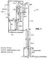
- Fig. 1 is a schematic representation of one embodiment of the invention in which heat is obtained from combustion of fuel.
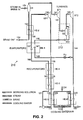
- Fig. 2 is a schematic representation of a second embodiment of the invention in which heat is obtained from geofluid containing steam and brine.
- Apparatus 110 for converting heat into mechanical energy.
- Apparatus 110 includes first and second closed loops 112, 114.
- Loop 112 includes water as a primary working fluid.
- Loop 114 includes a water/ammonia mixture as a multicomponent working fluid.
- Systems with multicomponent working fluids are described in Alexander I. Kalina's U.S. Patents Nos. 4,346,561; 4,489,563; 4,548,043; 4,586,340; 4,604,867; 4,732,005; 4,763,480; 4,899,545; 4,982,568; 5,029,444; 5,095,708; 5,440,882; 5,450,821, and applications serial nos. 08/283,091, 08/546,419 which are hereby incorporated by reference.
- closed loop 112 condensed liquid water with parameters as at point 56 is sent through tubes into boiler 116, which combusts corrosive and/or toxic fuels.
- boiler 116 In the tubes in boiler 116, water boils, producing dry, saturated steam with parameters as at point 51.
- Steam with parameters as at point 51 is divided into first and second primary streams having parameters as at points 41 and 52, respectively.
- the stream of steam with parameters as at point 41 is sent into the first stage of steam turbine ST-1, which is a first expander where the steam expands to an intermediate pressure, producing power and leaving ST-1 with parameters as at point 42.
- This steam, already wet, is sent into separator S in separator/splitter 118, where the liquid in the expanded first primary stream is separated from the vapor.
- Part of the separated vapor having parameters as at point 43 makes up a third primary stream that is sent into the second stage, ST-2 (a second expander) of the steam turbine.
- ST-2 a second expander
- the remainder of the steam and all of the liquid leaving separator S are combined to create a fourth primary stream with parameters as at point 45.
- the third primary stream of steam having parameters as at point 43 (see above) is expanded in the second stage of steam turbine ST-2, producing power and obtaining parameters as at point 44.
- second, third, and fourth primary streams of saturated or wet steam are created having parameters as at points 52, 44, and 45, respectively.
- the second primary stream with parameters as at point 52 has the highest pressure and temperature.
- the fourth primary stream with parameters as at point 45 has intermediate pressure and temperature, and the third primary stream with parameters as at point 44 has the lowest pressure and temperature, respectively.
- Steam in the second primary stream with parameters as at point 52 is sent into heat exchanger HE-1 where it is condensed and then subcooled, releasing heat and leaving HE-1 with parameters as at point 54.
- Steam in the fourth primary stream with parameters as at point 45 is sent into second heat exchanger HE-2 where it is condensed and subcooled, releasing heat and leaving third HE-2 with parameters as at point 46.
- This fourth primary stream is then pumped by pump P-2 up to a pressure equal to that of steam in the second primary stream having parameters as at point 54 (see above) and obtains parameters as at point 50.
- a fully-condensed multicomponent working fluid having parameters as at point 14 is pumped to the required high pressure by pump P-1 and obtains parameters as at point 21. Thereafter, a stream of multicomponent working fluid with parameters as at point 21 passes through fourth heat exchanger HE-4 where it is heated and obtains parameters as at point 60. Preferably the state of the working fluid at point 60 is a saturated liquid. Thereafter, the stream of multicomponent working fluid with parameters as at point 60 is passed through recuperative fifth heat exchanger HE-5 where it is partially vaporized, obtaining parameters as at point 62.
- a stream with parameters as at point 62, thereafter, is sent into third heat exchanger HE-3 (see above) where it is further heated and vaporized by heat released in third heat exchanger HE-3 and obtains parameters as at point 66. Thereafter, a stream of working fluid having parameters as at point 66 is sent into second heat exchanger HE-2 where it is further heated and fully vaporized by heat released in second heat exchanger HE-2.
- a stream of multicomponent working fluid leaving heat exchanger HE-2 with parameters as at point 68 enters first heat exchanger HE-1 where it is superheated by heat released in heat exchanger HE-1 and leaves with parameters as at point 30.
- a stream of multicomponent working fluid with parameters as at point 30 passes through working fluid turbine WFT (a second expander) where it is expanded, producing power and leaving WFT as a spent multicomponent working fluid with parameters as at point 36.
- the spent multicomponent working fluid with parameters as at point 36 passes through recuperative heat exchanger HE-5 where it is cooled and partially condensed, releasing heat (see above) and leaves HE-5 with parameters as at point 38.
- a stream of multicomponent working fluid with parameters as at point 38 enters recuperative heat exchanger HE-4 where it is further cooled and condensed, releasing heat (see above) and leaves HE-4 with parameters as at point 29.
- a stream of a partially condensed multicomponent working fluid having parameters as at point 29 passes through a condenser HE-6 where it is fully condensed by a stream of cooling water or cooling air 23-24 and obtains, as a result, parameters as at point 14.
- Apparatus 110 provides effective conversion of heat produced by combustion of toxic and corrosive fuels.
- a summary of performance of the proposed Fig. 1 system is presented in Table 2 and shows a net thermal efficiency of 28.14%.
- steam leaving the boiler with the identical parameters as at point 51 would produce a net efficiency of 21%.
- the Fig. 1 system increases efficiency of heat conversion and power generation by 33%.
- FIG. 2 there is shown power system 210 designed for utilization of heat from geofluid consisting of steam and brine.
- the high mineralization of brine limits the extent to which it can be practically cooled and results in conditions that are similar in some respects to the Fig. 1 system designed for utilization of corrosive and toxic fuels.
- the similarity of conditions permits some of the same principles to be utilized in geofluid power system 210.
- geofluid comprising steam and mineralized brine having parameters as at point 151 enters separator S-1 where it is separated into a stream of saturated steam having parameters as at point 141 and stream of mineralized liquid brine having parameters as at point 152.
- Stream of steam having parameters as at point 141 enters into the high pressure steam turbine ST-1, where it is expanded to intermediate pressure obtaining parameters as at point 142.
- Steam with parameters as at point 142 is wet and enters into separator S-2 in separator/splitter 212, where the liquid in the expanded steam is separated from the vapor and split into a first stream with parameters as at point 143 and a second stream with parameters as at point 146.
- Steam exiting separator S-2 is divided into two substreams with parameters as at point 143 and point 145, respectively. Thereafter, the first stream (steam with parameters as at point 143) is sent into the low pressure steam turbine ST-2 where it is expanded to a low pressure and produces useful energy.
- High pressure steam turbine ST-1 and low pressure steam turbine ST-2 are first and second stage expanders, respectively, for the steam. After expansion at low pressure turbine ST-2, the first stream obtains parameters as at point 144.
- Stream of steam with parameters as at point 145 is mixed with the liquid removed from separator S-2 and creates the second stream with parameters as at point 146.
- the second stream passes through first heat exchanger HE-1, where it is condensed and subcooled, exiting this heat exchanger with parameters as at point 148.
- stream of condensate with parameters as at point 148 is throttled at throttle valve TV to the pressure equal to the pressure of the stream from ST-2 having parameters as at point 144 and is mixed with this stream.
- stream of a partially condensed steam having parameters as at point 149 is created.
- the stream having parameters as at point 149 passes through steam condenser HE-6, where it is cooled by cooling water or air, and fully condenses, obtaining the parameters as at point 150.
- the condensed stream is then discharged from system 210.
- Liquid brine removed from separator S-1 and having parameters as at point 152 (see above) passes through second heat exchanger HE-2, where it is cooled and obtains parameters as at point 154. Heat released from the brine in heat exchanger HE-2 is transferred to a working fluid of the binary cycle which is described below. The cooled brine is thereafter discharged from system 210 at an acceptable temperature.
- Working fluid of a binary cycle which is fully condensed and having parameters as at point 114 is pumped by pump P-1 and obtains parameters as at point 121. Thereafter, the stream of working fluid with parameters as at point 121 passes through recuperative heat exchanger HE-3, where it is heated and obtains parameters as at point 160. The state of working fluid with parameters as at point 160 preferably is saturated liquid. Thereafter, the stream with parameters as at point 160 passes through heat exchanger HE-4 where it is partially boiled and obtains parameters as at point 166.
- the stream of working fluid having parameters as at point 166 passes through first heat exchanger HE-1, where it is heated by heat from the second stream from separator/splitter 212 and is fully vaporized, leaving heat exchanger HE-1 with parameters as at point 168.
- Multicomponent working fluid having parameters as at point 168 passes through second heat exchanger HE-2 where it is superheated by heat released in the process of cooling liquid geothermal brine.
- working fluid obtains parameters as at point 130 with which it enters the working fluid turbine WFT.
- turbine WFT working fluid is expanded producing work and obtaining parameters as at point 136.
- spent multicomponent working fluid having parameters as at point 136 passes through recuperative heat exchanger HE-4 where it is partially condensed and leaves this heat exchanger with parameters as at point 138.
- Heat released in heat exchanger HE-4 is utilized for initial evaporation of the working fluid (between points 160 and 166).
- working fluid having parameters as at point 138 passes through heat exchanger HE-3 where it is further condensed obtaining parameters as at point 129.
- Heat released in heat exchanger HE-3 is utilized for preheating of an oncoming stream of working fluid (between points 121 and 160) as described above.
- Stream of working fluid having parameters as at point 129 is further sent into condenser HE-5, where it is fully condensed by cooling water or air obtaining parameters as at point 114. The cycle of the working fluid is closed.
- Power system 210 shown on Fig. 2 being applied to the utilization of geothermal energy, provides increased efficiency of approximately 30% compared with the conventional systems in which steam is expanded fully to the lowest possible pressure, and liquid is throttled to produce additional steam which, as well, is expanded to the lowest possible pressure.
- Both described systems 110, 210 employ multi-stage expansion of steam which is used as a heat source with utilization of heat of condensation for heating and vaporizing a multicomponent working fluid in the closed binary cycle.
- the multicomponent working fluid in the binary cycle is a mixture of at least two components.
- the composition of components in the multicomponent working fluid is chosen in such a way as to provide that the initial temperature of condensation of a working fluid, after expansion, is higher than the initial temperature of boiling of the same working fluid before expansion. This, in turn, provides for recuperative initial boiling of oncoming working fluid.
Abstract
Description
- The invention relates to converting thermal energy (e.g., heat produced by the combustion of toxic and/or corrosive fuels such as municipal waste or heat from geofluid) into useful (e.g., mechanical and electrical) energy.
- In the process of combustion of fuels which generate toxic and/or corrosive flue gases, it is necessary to maintain the temperature of the boiler's tubes below some temperature level in order to prevent rapid corrosion of these tubes. This is usually achieved by circulating boiling water through these tubes and producing, as a result, saturated or slightly superheated steam. Conventionally, this steam is then subjected to expansion in a steam turbine, in order to produce useful power. However, because this steam is usually saturated or superheated only slightly, expansion of it causes the turbine to work in the wet region, which drastically reduces efficiency and longevity of the steam turbine. Because the steam turbine cannot operate in conditions where wetness of the vapor exceeds 12-13%, it is therefore often necessary to stop the expansion in the middle of the expansion and separate and remove the liquid and thereafter continue further expansion.
- Useful energy can also be obtained from geofluid containing steam and brine, as described, e.g., in U.S. Patent No. 5,440,882.
- In one aspect, the invention features, in general, converting heat in a primary fluid (e.g., steam) to useful energy by multistage expansion of the primary fluid, heating of a multicomponent working fluid in a separate closed loop using heat of the primary fluid, and expansion of the multicomponent working fluid. The primary fluid in a vapor state is expanded in a first stage expander to obtain useful energy and to produce a partially expanded primary fluid stream. The partially expanded primary fluid stream is then separated into liquid and vapor components and split into a vapor stream (which is expanded in a second stage expander) and a further primary stream (which used to heat the multicomponent working fluid).
- In preferred embodiments, spent multicomponent working fluid (that has been expanded) is condensed at a condenser and passed through a recuperative heat exchanger in which heat from the spent multicomponent working fluid is used to recuperatively heat the condensed multicomponent wording fluid. The primary fluid can be heated in a boiler or can be steam from a geofluid.
- In another aspect, the invention features, in general, converting heat to useful energy by using two closed loops. One closed loop contains a primary working fluid that is heated by an external source of heat (e.g., in a boiler combusting corrosive or toxic fuel) and then split into two streams. The first stream is expanded to obtain useful energy (e.g., in a turbine), and the second stream is used at a first heat exchanger to heat a multicomponent working fluid in the second closed loop. The heated multicomponent working fluid is then also expanded to obtain further useful energy (e.g., in a second turbine).
- In preferred embodiments the first stream is split into two streams, one of which is a vapor stream that is expanded to obtain useful energy, and both of the additional streams are used to also heat the multicomponent working fluid at two further heat exchangers.
- In another aspect, the invention features, in general, a power system for converting heat in a geofluid containing steam and brine to useful energy. The steam is separated from the brine and expanded, and heat in the steam is used to heat a multicomponent working fluid in a separate closed loop at a first heat exchanger. The separated brine is used to further heat the multicomponent working fluid at a second heat exchanger, and is then discharged from the system. The multicomponent working fluid is then expanded to obtain further useful energy.
- In preferred embodiments the spent multicomponent working fluid is condensed at a condenser and passed through a recuperative heat exchanger in which heat from the spent multicomponent working fluid is used to recuperatively heat the multicomponent working fluid after being condensed at the condenser. The heat used to heat the multicomponent working fluid in the first heat exchanger is obtained from steam that has been expanded and then split into two streams. One stream is a vapor that is expanded to obtain useful energy, and the other stream passes through the first heat exchanger, and is thereafter throttled and recombined with the expanded stream.
- Other advantages and features of the invention will be apparent from the following description of particular embodiments thereof and from the claims.
- Fig. 1 is a schematic representation of one embodiment of the invention in which heat is obtained from combustion of fuel.
- Fig. 2 is a schematic representation of a second embodiment of the invention in which heat is obtained from geofluid containing steam and brine.
- Referring to Fig. 1, there is shown
apparatus 110 for converting heat into mechanical energy.Apparatus 110 includes first and second closedloops Loop 112 includes water as a primary working fluid.Loop 114 includes a water/ammonia mixture as a multicomponent working fluid. Systems with multicomponent working fluids are described in Alexander I. Kalina's U.S. Patents Nos. 4,346,561; 4,489,563; 4,548,043; 4,586,340; 4,604,867; 4,732,005; 4,763,480; 4,899,545; 4,982,568; 5,029,444; 5,095,708; 5,440,882; 5,450,821, and applications serial nos. 08/283,091, 08/546,419 which are hereby incorporated by reference. - In closed
loop 112, condensed liquid water with parameters as atpoint 56 is sent through tubes intoboiler 116, which combusts corrosive and/or toxic fuels. In the tubes inboiler 116, water boils, producing dry, saturated steam with parameters as atpoint 51. Steam with parameters as atpoint 51 is divided into first and second primary streams having parameters as atpoints 41 and 52, respectively. The stream of steam with parameters as at point 41 is sent into the first stage of steam turbine ST-1, which is a first expander where the steam expands to an intermediate pressure, producing power and leaving ST-1 with parameters as at point 42. This steam, already wet, is sent into separator S in separator/splitter 118, where the liquid in the expanded first primary stream is separated from the vapor. Part of the separated vapor having parameters as atpoint 43 makes up a third primary stream that is sent into the second stage, ST-2 (a second expander) of the steam turbine. The remainder of the steam and all of the liquid leaving separator S are combined to create a fourth primary stream with parameters as atpoint 45. The third primary stream of steam having parameters as at point 43 (see above) is expanded in the second stage of steam turbine ST-2, producing power and obtaining parameters as atpoint 44. As a result, second, third, and fourth primary streams of saturated or wet steam are created having parameters as atpoints point 52 has the highest pressure and temperature. The fourth primary stream with parameters as atpoint 45 has intermediate pressure and temperature, and the third primary stream with parameters as atpoint 44 has the lowest pressure and temperature, respectively. Steam in the second primary stream with parameters as atpoint 52 is sent into heat exchanger HE-1 where it is condensed and then subcooled, releasing heat and leaving HE-1 with parameters as atpoint 54. Steam in the fourth primary stream with parameters as atpoint 45 is sent into second heat exchanger HE-2 where it is condensed and subcooled, releasing heat and leaving third HE-2 with parameters as atpoint 46. This fourth primary stream is then pumped by pump P-2 up to a pressure equal to that of steam in the second primary stream having parameters as at point 54 (see above) and obtains parameters as atpoint 50. Steam in the third primary stream with parameters as atpoint 44 is sent into third heat exchanger HE-3 where it is condensed and subcooled, releasing heat and leaving heat exchanger HE-3 with parameters as atpoint 48. This third primary stream is then pumped by pump P-3 to a pressure equal to that of the second and fourth primary steams having parameters as atpoints 54 and 50 (see above) and obtains parameters as atpoint 49. Thereafter, second, third, and fourth primary streams having parameters as atpoints point 55. This stream is then pumped by pump P-4 to the required pressure, acquiring parameters as at point 56 (see above), and is sent intoboiler 116. - In second closed
loop 114, a fully-condensed multicomponent working fluid having parameters as atpoint 14 is pumped to the required high pressure by pump P-1 and obtains parameters as atpoint 21. Thereafter, a stream of multicomponent working fluid with parameters as atpoint 21 passes through fourth heat exchanger HE-4 where it is heated and obtains parameters as at point 60. Preferably the state of the working fluid at point 60 is a saturated liquid. Thereafter, the stream of multicomponent working fluid with parameters as at point 60 is passed through recuperative fifth heat exchanger HE-5 where it is partially vaporized, obtaining parameters as atpoint 62. A stream with parameters as atpoint 62, thereafter, is sent into third heat exchanger HE-3 (see above) where it is further heated and vaporized by heat released in third heat exchanger HE-3 and obtains parameters as atpoint 66. Thereafter, a stream of working fluid having parameters as atpoint 66 is sent into second heat exchanger HE-2 where it is further heated and fully vaporized by heat released in second heat exchanger HE-2. A stream of multicomponent working fluid leaving heat exchanger HE-2 with parameters as at point 68 (preferably in the state of saturated vapor), enters first heat exchanger HE-1 where it is superheated by heat released in heat exchanger HE-1 and leaves with parameters as atpoint 30. A stream of multicomponent working fluid with parameters as atpoint 30 passes through working fluid turbine WFT (a second expander) where it is expanded, producing power and leaving WFT as a spent multicomponent working fluid with parameters as atpoint 36. The spent multicomponent working fluid with parameters as atpoint 36 passes through recuperative heat exchanger HE-5 where it is cooled and partially condensed, releasing heat (see above) and leaves HE-5 with parameters as atpoint 38. Thereafter, a stream of multicomponent working fluid with parameters as atpoint 38 enters recuperative heat exchanger HE-4 where it is further cooled and condensed, releasing heat (see above) and leaves HE-4 with parameters as at point 29. A stream of a partially condensed multicomponent working fluid having parameters as at point 29 passes through a condenser HE-6 where it is fully condensed by a stream of cooling water or cooling air 23-24 and obtains, as a result, parameters as atpoint 14. - All specific parameters of all key points of the described process are presented in Table 1.
-
Apparatus 110 provides effective conversion of heat produced by combustion of toxic and corrosive fuels. A summary of performance of the proposed Fig. 1 system is presented in Table 2 and shows a net thermal efficiency of 28.14%. In a traditional system based on direct expansion of the steam, steam leaving the boiler with the identical parameters as atpoint 51 would produce a net efficiency of 21%. As a result, the Fig. 1 system increases efficiency of heat conversion and power generation by 33%. - Referring to Fig. 2, there is shown
power system 210 designed for utilization of heat from geofluid consisting of steam and brine. The high mineralization of brine limits the extent to which it can be practically cooled and results in conditions that are similar in some respects to the Fig. 1 system designed for utilization of corrosive and toxic fuels. The similarity of conditions permits some of the same principles to be utilized ingeofluid power system 210. - In
geofluid power system 210, geofluid comprising steam and mineralized brine having parameters as atpoint 151 enters separator S-1 where it is separated into a stream of saturated steam having parameters as atpoint 141 and stream of mineralized liquid brine having parameters as atpoint 152. Stream of steam having parameters as atpoint 141 enters into the high pressure steam turbine ST-1, where it is expanded to intermediate pressure obtaining parameters as atpoint 142. Steam with parameters as atpoint 142 is wet and enters into separator S-2 in separator/splitter 212, where the liquid in the expanded steam is separated from the vapor and split into a first stream with parameters as atpoint 143 and a second stream with parameters as atpoint 146. Steam exiting separator S-2 is divided into two substreams with parameters as atpoint 143 andpoint 145, respectively. Thereafter, the first stream (steam with parameters as at point 143) is sent into the low pressure steam turbine ST-2 where it is expanded to a low pressure and produces useful energy. High pressure steam turbine ST-1 and low pressure steam turbine ST-2 are first and second stage expanders, respectively, for the steam. After expansion at low pressure turbine ST-2, the first stream obtains parameters as atpoint 144. Stream of steam with parameters as atpoint 145 is mixed with the liquid removed from separator S-2 and creates the second stream with parameters as atpoint 146. The second stream passes through first heat exchanger HE-1, where it is condensed and subcooled, exiting this heat exchanger with parameters as atpoint 148. Thereafter, stream of condensate with parameters as atpoint 148 is throttled at throttle valve TV to the pressure equal to the pressure of the stream from ST-2 having parameters as atpoint 144 and is mixed with this stream. As a result of such a mixing, the stream of a partially condensed steam having parameters as atpoint 149 is created. The stream having parameters as atpoint 149 passes through steam condenser HE-6, where it is cooled by cooling water or air, and fully condenses, obtaining the parameters as atpoint 150. The condensed stream is then discharged fromsystem 210. - Liquid brine removed from separator S-1 and having parameters as at point 152 (see above) passes through second heat exchanger HE-2, where it is cooled and obtains parameters as at
point 154. Heat released from the brine in heat exchanger HE-2 is transferred to a working fluid of the binary cycle which is described below. The cooled brine is thereafter discharged fromsystem 210 at an acceptable temperature. - Working fluid of a binary cycle which is fully condensed and having parameters as at
point 114 is pumped by pump P-1 and obtains parameters as atpoint 121. Thereafter, the stream of working fluid with parameters as atpoint 121 passes through recuperative heat exchanger HE-3, where it is heated and obtains parameters as atpoint 160. The state of working fluid with parameters as atpoint 160 preferably is saturated liquid. Thereafter, the stream with parameters as atpoint 160 passes through heat exchanger HE-4 where it is partially boiled and obtains parameters as atpoint 166. Thereafter, the stream of working fluid having parameters as atpoint 166 passes through first heat exchanger HE-1, where it is heated by heat from the second stream from separator/splitter 212 and is fully vaporized, leaving heat exchanger HE-1 with parameters as atpoint 168. Multicomponent working fluid having parameters as atpoint 168 passes through second heat exchanger HE-2 where it is superheated by heat released in the process of cooling liquid geothermal brine. As a result of heating in heat exchanger HE-1, working fluid obtains parameters as atpoint 130 with which it enters the working fluid turbine WFT. In turbine WFT, working fluid is expanded producing work and obtaining parameters as atpoint 136. Thereafter, spent multicomponent working fluid having parameters as atpoint 136 passes through recuperative heat exchanger HE-4 where it is partially condensed and leaves this heat exchanger with parameters as atpoint 138. Heat released in heat exchanger HE-4 is utilized for initial evaporation of the working fluid (betweenpoints 160 and 166). Thereafter, working fluid having parameters as atpoint 138 passes through heat exchanger HE-3 where it is further condensed obtaining parameters as atpoint 129. Heat released in heat exchanger HE-3 is utilized for preheating of an oncoming stream of working fluid (betweenpoints 121 and 160) as described above. Stream of working fluid having parameters as atpoint 129 is further sent into condenser HE-5, where it is fully condensed by cooling water or air obtaining parameters as atpoint 114. The cycle of the working fluid is closed. - In
power system 210, heat of condensation of steam after the second stage of a turbine (ST-2) is not used for heating and vaporizing working fluid in the binary cycle (as insystem 110 in Fig. 1) but rather is rejected to the ambient. This is because such heat is of a very low temperature and does not contain the potential to generate power. -
Power system 210 shown on Fig. 2, being applied to the utilization of geothermal energy, provides increased efficiency of approximately 30% compared with the conventional systems in which steam is expanded fully to the lowest possible pressure, and liquid is throttled to produce additional steam which, as well, is expanded to the lowest possible pressure. - The parameters of all streams in
power system 210 at all of the key points are presented in Table 3, and the summary of performance of this system is presented in Table 4. - Both described
systems - Other embodiments of the invention are within the scope of the appended claims. For example, it is possible in the system presented on Fig. 1, to use as a source of heat not steam but a mixture of steam and liquid and use the heat released by cooling this liquid for superheating the working fluid of a binary cycle.
Table 1 # PpsiA X T°F H BTU/lb G/G30 Flow lb/hr Phase 14 115.93 .7338 86 -15.96 1 93,701 SatLiquid 21 534 .7338 87.46 -13.64 1 93,701 Liq 1 0° 29 116.23 .7338 160.12 375.03 1 93,701 Wet .4203 30 495 .7338 590 974.33 1 93,701 Vap 237° 36 117.53 .7338 354.53 851.83 1 93,701 Vap 9 ° 37 116.83 .7338 257.18 796.41 1 93,701 SatVapor 38 116.53 .7338 201.10 497.89 1 93,701 Wet .3001 41 1529.67 Steam 599 1166.81 .6106 57,213 SatVapor 42 664 Steam 497.37 1116.46 .6106 57,213 Wet .12 43 664 Steam 497.37 1202.61 .4137 38,767 SatVapor 44 161.13 Steam 364.16 1109.19 .4137 38,767 Wet .1009 45 664 Steam 497.37 935.26 .1969 18,446 Wet .3724 46 664 Steam 497.37 484.38 .1969 18,446 SatLiquid 48 146.13 Steam 277.12 246.23 .4137 38,767 Liq 79° 49 1514.67 Steam 280.20 252.05 .4137 38,767 Liq 317° 50 1514.67 Steam 501.26 488.66 .1969 18,446 Liq 96° 51 1529.67 Steam 599 1166.81 .7064 66,186 SatVapor 52 1529.67 Steam 599 1166.81 .0958 8,973 SatVapor 54 1514.67 Steam 497.37 484.13 .0958 8,973 Liq 100° 55 1514.67 Steam 374.55 349.45 .7064 66,186 Liq 223° 56 1559.67 Steam 374.66 349.63 .7064 66,186 Liq 227° 60 524 .7338 195.70 109.22 1 93,701 SatLiquid 61 519 .7338 251.78 407.74 1 93,701 Wet .4732 62 514 .7338 268.12 463.16 1 93,701 Wet .4029 66 509 .7338 355.16 820.19 1 93,701 SatVapor 68 502 .7338 488.37 908.95 1 93,701 Vap 134° 23 • Air 68 8.75 64.1617 6,012,004 24 • Air 93.08 14.84 64.1617 6,012,004 Table 2 Performance Summary KCS23 Heat to Steam Boiler 15851.00 kW 577.22 BTU/lb Heat Rejected 10736.96 kW 390.99 BTU/lb Σ Turbine Expansion Work 5269.74 kW 191.90 BTU/lb Gross Electrical Output 4900.86 kW 178.47 BTU/lb Cycle Pump Power 166.12 kW 6.05 BTU/lb Cooling Air Fans 139.98 kW 5.10 BTU/lb Plant Net Output 4594.76 kW 167.32 BTU/lb Gross Cycle Efficiency 29.87 % Net Thermal Efficiency 28.99 % First Law Efficiency 33.25 % Second Law Efficiency 68.22 % Second Law Maximum 48.73 % Turbine Heat Rate 11771.21 BTU/kWh Water-Ammonia Flow Rate 93700.80 lb/hr Table 3 # PpsiA X T°F H BTU/lb G/G30 Flow lb/hr Phase 14 130.95 .7102 96.80 -9.16 1 394,231 SatLiquid 21 614.50 .7102 98.22 -6.81 1 394,231 Liq 116i 29 131.25 .7102 176.70 384.01 1 394,231 Wet .4328 30 588.50 .7102 404.60 858.49 1 394,231 Vap 32i 36 132.55 .7102 262.96 758.47 1 394,231 Wet .0575 38 131.55 .7102 217.40 513.95 1 394,231 Wet .3053 41 276.62 Steam 410 1202.84 .8152 321,374 SatVapor 42 52.40 Steam 284 1096.43 .8152 321,374 Wet .0854 43 52.49 Steam 284 1175.14 .6673 263,089 SatVapor 44 2.50 Steam 134.29 1009.19 .6673 263,089 Wet .1083 45 52.40 Steam 284 1175.14 .0783 30,852 SatVapor 46 52.40 Steam 284 741.16 .1478 58,285 Wet .4707 48 52.40 Steam 262.95 232.04 .1478 58,285 Liq 21i 49 2.50 Steam 134.29 868.24 .8152 321,374 Wet .2468 50 2.50 Steam 134.29 102.05 .8152 321,374 SatLiquid 51 • Brine 410 385.56 3.2336 1,274,773 54 • Brine 284 257.04 3.2336 1,274,773 60 599.50 .7102 212 123.12 1 394,231 SatLiquid 66 594.50 .7102 257.55 367.64 1 394,231 Wet .557 68 589.50 .7102 278.60 442.91 1 394,231 Wet .4559 23 • Water 87.80 55.80 24.6244 9,707,684 59 • Water 132.85 100.85 8.7270 3,440,442 58 • Water 127.09 95.09 15.8974 6,267,242 24 • Water 129.13 97.13 24.6244 9,707,684 Table 4 Performance Summary KCS21 Heat in 151693.12 kW 1312.93 BTU/lb Heat rejected 117591.11 kW 1017.77 BTU/lb _Turbine enthalpy drops 34373.80 kW 297.51 BTU/lb Turbine Work 33514.45 kW 290.07 BTU/lb Feed pump Æ H 2.35, power 288.77 kW 2.50 BTU/lb Feed + Coolant pump power 632.05 kW 5.47 BTU/lb Net Work 32882.40 kW 284.60 BTU/lb Gross Output 33514.45 kWe Cycle Output 33225.68 kWe Net Output 32882.40 kWe Net thermal efficiency 21.68 % Second law limit 30.80 % Second law efficiency 70.37 % Specific Brine Consumption 38.77 lb/kW hr Specific Power Output 25.79 Watt hr/lb
Claims (48)
- A method of converting heat to useful energy comprisingexpanding a primary fluid in a vapor state in a first stage expander to obtain useful energy and to produce a partially expanded primary fluid stream having vapor and liquid components,separating said partially expanded primary fluid stream into liquid and vapor components and splitting said stream into a vapor stream and a further primary stream including liquid,expanding said vapor stream in a second stage expander to obtain useful energy,using heat in said partially expanded primary fluid stream to heat a multicomponent working fluid in a separate closed loop at a primary heat exchanger, andexpanding said multicomponent working fluid in a further expander in said separate closed loop to obtain useful energy and produce a spent multicomponent working fluid.
- The method of claim 1 wherein said spent multicomponent working fluid is condensed at a condenser and passed through a recuperative heat exchanger in which heat from said spent multicomponent working fluid is used to recuperatively heat said multicomponent working fluid after being condensed at said condenser.
- The method of claim 1 wherein said primary fluid in a vapor state is steam.
- The method of claim 3 wherein said steam is generated by heating said primary fluid in a primary closed loop in a boiler.
- The method of claim 4 wherein said heating includes burning corrosive or toxic fuels.
- The method of claim 5 wherein said primary fluid in a vapor state is split into a first primary stream that is expanded at said first stage expander and a second primary stream that is used to further heat said multicomponent working fluid before it is expanded.
- The method of claim 6 wherein said further primary stream is used to heat said multicomponent working fluid before it is heated at said primary heat exchanger.
- The method of claim 3 wherein said primary fluid in a vapor state is obtained from a geofluid.
- The method of claim 8 further comprising separating said steam from brine in said geofluid, and using said brine to further heat said multicomponent working fluid before it is expanded.
- Apparatus for converting heat to useful energy comprisinga first stage expander in which a primary fluid in a vapor state is expanded to obtain useful energy and to produce a partially expanded primary fluid stream having vapor and liquid components,a separator/splitter that separates said partially expanded primary fluid stream from said first stage expander into liquid and vapor components and splits said stream into a vapor stream and a further primary stream including liquid,a second stage expander in which said vapor stream from said separator/splitter is expanded to obtain useful energy,a primary heat exchanger connected to use heat in said partially expanded primary fluid stream to heat a multicomponent working fluid, anda separate closed loop containing said multicomponent working fluid, said second closed loop including flow passages in said primary heat exchanger, said second closed loop including a further expander in which said multicomponent working fluid is expanded to obtain useful energy and produce a spent multicomponent working fluid.
- The apparatus of claim 10 wherein said separate closed loop includes a condenser at which said spent multicomponent working fluid is condensed and a recuperative heat exchanger in which heat from said spent multicomponent working fluid is used to recuperatively heat said multicomponent working fluid after being condensed at said condenser.
- The apparatus of claim 10 wherein said primary fluid in a vapor state is steam.
- The apparatus of claim 12 wherein said steam is generated by heating a primary working fluid in a closed loop in a boiler.
- The apparatus of claim 13 wherein said boiler burns corrosive or toxic fuels.
- The apparatus of claim 14 further comprising a stream splitter at which said primary fluid in a vapor state is split into a first primary stream that is expanded at said first stage expander and a second primary stream that is used to further heat said multicomponent working fluid before it is expanded.
- The apparatus of claim 15 wherein said further primary stream is connected to heat said multicomponent working fluid before it is heated at said primary heat exchanger.
- The apparatus of claim 12 wherein said primary fluid in a vapor state is obtained from a geofluid.
- The apparatus of claim 17 further comprising a separator at which said steam is separated from brine in said geofluid, and a further heat exchanger in which heat from said brine is used to further heat said multicomponent working fluid before it is expanded.
- A method of converting heat to useful energy comprisingheating a primary working fluid in a first closed loop with an external source of heat,splitting said heated primary working fluid into a first primary stream and a second primary stream,expanding said first primary stream in a first expander to obtain useful energy,using heat in said second primary stream to heat a multicomponent working fluid in a second closed loop at a first heat exchanger, andexpanding said multicomponent working fluid in a second expander to obtain useful energy.
- The method of claim 19 wherein said heating includes combusting corrosive or toxic fuels.
- The method of claim 20 wherein said primary working fluid is steam.
- The method of claim 19 wherein heat in said first primary stream is used to heat said multicomponent working fluid in a second heat exchanger after expansion in said first expander.
- The method of claim 22 wherein said first primary stream is separated into liquid and vapor components and is split into third and fourth primary streams after expansion in said first expander, said third primary stream being a vapor that is expanded in a third expander to obtain useful energy, said fourth primary stream passing through said second heat exchanger.
- The method of claim 23 wherein heat in said third primary stream is used to heat said multicomponent working fluid in a third heat exchanger after expansion in said third expander.
- The method of claim 24 wherein said second, third, and fourth primary streams are combined to provide said primary working fluid that is heated by said heater.
- The method of claim 25 wherein said first primary stream is separated into liquid and vapor phases at a separator after expansion in said first expander, part of said vapor phase providing said third primary stream and part of said vapor phase being joined with said liquid phase to provide said fourth primary stream.
- The method of claim 19 wherein said multicomponent working fluid is condensed at a condenser, after expansion at said second expander, and passed through a fourth heat exchanger in which heat from said multicomponent working fluid prior to condensing is used to recuperatively heat said multicomponent working fluid after being condensed at said condenser.
- Apparatus for converting heat to useful energy comprisinga first closed loop containing a primary working fluid and including a heater for heating said primary working fluid, and a first stream splitter that splits said heated primary working fluid into a first primary stream and a second primary stream, said first closed loop also including a first expander in which said first primary stream is expanded to obtain useful energy, said first closed loop also including a flow passage through a first heat exchanger to transfer heat from said second primary stream to a multicomponent working fluid, anda second closed loop containing said multicomponent working fluid, said second closed loop including a flow passage through said first heat exchanger, said second closed loop including a second expander in which said multicomponent working fluid is expanded to obtain useful energy.
- The apparatus of claim 28 wherein said heater is a boiler in which corrosive or toxic fuels are combusted.
- The apparatus of claim 28 wherein said primary working fluid is steam.
- The apparatus of claim 28 wherein said first closed loop and said second closed loop include passages in a second heat exchanger in which heat from said first primary stream is used to heat said multicomponent working fluid.
- The apparatus of claim 31 wherein said first closed loop includes a separator/splitter that separates said first primary stream into liquid and vapor phases and splits said first primary stream into third and fourth primary streams after expansion in said first expander, said third primary stream being a vapor, said first closed loop also including a third expander thorough which said third primary stream passes and in which said third primary stream is expanded, said fourth primary stream passing thorough said second heat exchanger.
- The apparatus of claim 32 wherein said first closed loop and said second closed loop include passages in a third heat exchanger in which heat from said third primary stream is used to heat said multicomponent working fluid.
- The apparatus of claim 33 wherein said first closed loop includes a stream combiner at which said second, third, and fourth primary streams are combined to provide said primary working fluid that is heated by said heater.
- The apparatus of claim 32 wherein said separator/splitter includes a separator that separates said first primary stream into liquid and vapor phases and a second stream splitter at which said vapor phase is split into said third primary stream and a further stream, and wherein said separator/splitter further comprises a stream combiner that combines said further stream and said liquid phase into said fourth primary stream.
- The apparatus of claim 28 wherein said second closed loop includes a condenser in which said multicomponent working fluid is condensed and a fourth heat exchanger in which heat from said multicomponent working fluid prior to condensing is used to recuperatively heat said multicomponent working fluid after being condensed at said condenser.
- A method of converting heat in a geofluid containing steam and brine to useful energy in a power system comprisingseparating said steam from said brine in said geofluid,expanding said steam in a first expander producing a stream of expanded steam,using heat in said steam to heat a multicomponent working fluid in a separate closed loop at a first heat exchanger,using said brine to further heat said multicomponent working fluid from said first heat exchanger at a second heat exchanger,discharging said brine from said second heat exchanger from the system, andexpanding said multicomponent working fluid in a second expander in said separate closed loop to obtain useful energy and produce a spent multicomponent working fluid.
- The method of claim 37 wherein said spent multicomponent working fluid is condensed at a condenser and passed through a recuperative heat exchanger in which heat from said spent multicomponent working fluid is used to recuperatively heat said multicomponent working fluid after being condensed at said condenser.
- The method of claim 38 wherein said heat used to heat said multicomponent working fluid in said first heat exchanger is obtained from steam that has been expanded in said first expander.
- The method of claim 39 wherein said stream of expanded steam is separated into liquid and vapor components and is split into first and second streams after expansion in said first expander, said first stream being a vapor that is expanded in a third expander to obtain useful energy, said second stream passing through said first heat exchanger.
- The method of claim 40 wherein said second stream is throttled after passing through said first heat exchanger and combined with said first stream after said first stream has been expanded in said third expander.
- The method of claim 41 wherein the combined first and second streams are condensed and discharged from the system.
- Apparatus for converting heat in a geofluid containing steam and brine to useful energy in a power system comprisinga separator that separates said steam from said brine in said geofluid,a first expander that expands said steam to obtain useful energy and produces a stream of expanded steam,a separate closed loop containing a multicomponent working fluid, said second closed loop including flow passages in a first heat exchanger in which heat in said steam is used to heat said multicomponent working fluid, said second closed loop including flow passages in a second heat exchanger in which said brine further heats said multicomponent working fluid from said first heat exchanger, said second closed loop including a second expander in which said multicomponent working fluid from said second heat exchanger is expanded to obtain useful energy and produce a spent multicomponent working fluid, andan outflow line connected to discharge said brine from said second heat exchanger from the system.
- The apparatus of claim 43 wherein said separate closed loop includes a condenser in which said spent multicomponent working fluid is condensed and a recuperative heat exchanger in which heat from said spent multicomponent working fluid is used to recuperatively heat said multicomponent working fluid after being condensed at said condenser.
- The apparatus of claim 44 wherein said heat used to heat said multicomponent working fluid in said first heat exchanger is obtained from steam that has been expanded in said first expander.
- The apparatus of claim 45 further comprising a separator/splitter that separates said stream of expanded steam into liquid and vapor components and splits said stream of expanded steam into first and second streams, said first stream being a vapor, and further comprising a third expander through which said first stream passes and in which said first stream is expanded to obtain useful energy, said second stream passing through said first heat exchanger.
- The apparatus of claim 46 further comprising a throttle valve in which said second stream is throttled after passing through said first heat exchanger and a junction at which said second stream from said throttle valve is combined with said first stream after said first stream has been expanded in said third expander.
- The apparatus of claim 47 wherein the combined first and second streams are condensed and discharged from the system.
Applications Claiming Priority (2)
| Application Number | Priority Date | Filing Date | Title |
|---|---|---|---|
| US598950 | 1996-02-09 | ||
| US08/598,950 US5822990A (en) | 1996-02-09 | 1996-02-09 | Converting heat into useful energy using separate closed loops |
Publications (2)
| Publication Number | Publication Date |
|---|---|
| EP0790391A2 true EP0790391A2 (en) | 1997-08-20 |
| EP0790391A3 EP0790391A3 (en) | 2000-07-19 |
Family
ID=24397596
Family Applications (1)
| Application Number | Title | Priority Date | Filing Date |
|---|---|---|---|
| EP97300810A Withdrawn EP0790391A3 (en) | 1996-02-09 | 1997-02-07 | Converting heat into useful energy |
Country Status (19)
| Country | Link |
|---|---|
| US (1) | US5822990A (en) |
| EP (1) | EP0790391A3 (en) |
| JP (3) | JP3961058B2 (en) |
| KR (1) | KR970062323A (en) |
| CN (1) | CN1100933C (en) |
| AR (1) | AR005755A1 (en) |
| AU (1) | AU723964B2 (en) |
| BR (1) | BR9700926A (en) |
| CA (1) | CA2197038C (en) |
| CO (1) | CO4560511A1 (en) |
| EA (1) | EA000058B1 (en) |
| GT (1) | GT199700021A (en) |
| IL (1) | IL120178A (en) |
| IS (1) | IS1792B (en) |
| NO (1) | NO307225B1 (en) |
| NZ (1) | NZ314206A (en) |
| TR (1) | TR199700105A2 (en) |
| TW (1) | TW330234B (en) |
| ZA (1) | ZA971039B (en) |
Cited By (2)
| Publication number | Priority date | Publication date | Assignee | Title |
|---|---|---|---|---|
| WO2004009964A1 (en) * | 2002-07-22 | 2004-01-29 | Douglas Wilbert Paul Smith | Method of converting energy |
| WO2008124868A1 (en) * | 2007-04-13 | 2008-10-23 | Renewable Energy Systems Limited | Power generation and energy recovery systems and methods |
Families Citing this family (39)
| Publication number | Priority date | Publication date | Assignee | Title |
|---|---|---|---|---|
| US6694740B2 (en) | 1997-04-02 | 2004-02-24 | Electric Power Research Institute, Inc. | Method and system for a thermodynamic process for producing usable energy |
| US5953918A (en) * | 1998-02-05 | 1999-09-21 | Exergy, Inc. | Method and apparatus of converting heat to useful energy |
| KR100302586B1 (en) * | 1998-03-27 | 2001-10-19 | 김영환 | Method for switching powerdown and sleep mode of pc card ata card |
| US6924781B1 (en) * | 1998-09-11 | 2005-08-02 | Visible Tech-Knowledgy, Inc. | Smart electronic label employing electronic ink |
| US6170263B1 (en) | 1999-05-13 | 2001-01-09 | General Electric Co. | Method and apparatus for converting low grade heat to cooling load in an integrated gasification system |
| US6347520B1 (en) | 2001-02-06 | 2002-02-19 | General Electric Company | Method for Kalina combined cycle power plant with district heating capability |
| US6829895B2 (en) | 2002-09-12 | 2004-12-14 | Kalex, Llc | Geothermal system |
| US6820421B2 (en) | 2002-09-23 | 2004-11-23 | Kalex, Llc | Low temperature geothermal system |
| US6735948B1 (en) | 2002-12-16 | 2004-05-18 | Icalox, Inc. | Dual pressure geothermal system |
| US6769256B1 (en) | 2003-02-03 | 2004-08-03 | Kalex, Inc. | Power cycle and system for utilizing moderate and low temperature heat sources |
| RS52092B (en) * | 2003-02-03 | 2012-06-30 | Kalex Llc. | Process and device for implementing thermodynamic cycle for utilizing moderate and low temperature heat sources |
| US7305829B2 (en) * | 2003-05-09 | 2007-12-11 | Recurrent Engineering, Llc | Method and apparatus for acquiring heat from multiple heat sources |
| US7264654B2 (en) * | 2003-09-23 | 2007-09-04 | Kalex, Llc | Process and system for the condensation of multi-component working fluids |
| US7065967B2 (en) * | 2003-09-29 | 2006-06-27 | Kalex Llc | Process and apparatus for boiling and vaporizing multi-component fluids |
| CA2543470A1 (en) * | 2003-10-21 | 2005-05-12 | Petroleum Analyzer Company, Lp | An improved combustion apparatus and methods for making and using same |
| US8117844B2 (en) * | 2004-05-07 | 2012-02-21 | Recurrent Engineering, Llc | Method and apparatus for acquiring heat from multiple heat sources |
| GB2450754B8 (en) * | 2007-07-06 | 2013-02-06 | Greenfield Energy Ltd | Geothermal energy system and method of operation |
| GB2450755B (en) | 2007-07-06 | 2012-02-29 | Greenfield Energy Ltd | Geothermal energy system and method of operation |
| GB2461029B (en) * | 2008-06-16 | 2011-10-26 | Greenfield Energy Ltd | Thermal energy system and method of operation |
| EP2204553A1 (en) * | 2008-06-23 | 2010-07-07 | Siemens Aktiengesellschaft | Steam power assembly |
| US8087248B2 (en) | 2008-10-06 | 2012-01-03 | Kalex, Llc | Method and apparatus for the utilization of waste heat from gaseous heat sources carrying substantial quantities of dust |
| US8695344B2 (en) * | 2008-10-27 | 2014-04-15 | Kalex, Llc | Systems, methods and apparatuses for converting thermal energy into mechanical and electrical power |
| US8176738B2 (en) | 2008-11-20 | 2012-05-15 | Kalex Llc | Method and system for converting waste heat from cement plant into a usable form of energy |
| MX2011010342A (en) | 2009-04-01 | 2012-01-25 | Linum Systems Ltd | Waste heat air conditioning system. |
| US8474263B2 (en) | 2010-04-21 | 2013-07-02 | Kalex, Llc | Heat conversion system simultaneously utilizing two separate heat source stream and method for making and using same |
| GB2488797A (en) | 2011-03-08 | 2012-09-12 | Greenfield Master Ipco Ltd | Thermal Energy System and Method of Operation |
| JP5999322B2 (en) * | 2011-06-03 | 2016-09-28 | 戸田工業株式会社 | Power generation system |
| US20120324885A1 (en) * | 2011-06-27 | 2012-12-27 | Turbine Air Systems Ltd. | Geothermal power plant utilizing hot geothermal fluid in a cascade heat recovery apparatus |
| CN102305113A (en) * | 2011-09-13 | 2012-01-04 | 上海盛合新能源科技有限公司 | Low-temperature waste heat recycling equipment in petrochemical industry |
| CN102338047A (en) * | 2011-09-13 | 2012-02-01 | 上海盛合新能源科技有限公司 | Geothermal power generating device |
| DE102012100967A1 (en) * | 2012-02-07 | 2013-08-08 | Levitec Gmbh | Arrangement for preheating fluid in steam power plant, has capacitor which is arranged between desuperheater or expansion device, and condenser |
| US8833077B2 (en) | 2012-05-18 | 2014-09-16 | Kalex, Llc | Systems and methods for low temperature heat sources with relatively high temperature cooling media |
| US9638175B2 (en) * | 2012-10-18 | 2017-05-02 | Alexander I. Kalina | Power systems utilizing two or more heat source streams and methods for making and using same |
| JP6013140B2 (en) * | 2012-11-01 | 2016-10-25 | 株式会社東芝 | Power generation system |
| WO2015165477A1 (en) | 2014-04-28 | 2015-11-05 | El-Monayer Ahmed El-Sayed Mohamed Abd El-Fatah | High efficiency power plants |
| WO2016067225A2 (en) * | 2014-10-31 | 2016-05-06 | Subodh Verma | A system for high efficiency energy conversion cycle by recycling latent heat of vaporization |
| JP6526432B2 (en) * | 2015-02-09 | 2019-06-05 | 日野自動車株式会社 | Waste heat recovery system |
| RU187281U1 (en) * | 2018-10-17 | 2019-02-28 | Общество с ограниченной ответственностью "Геотерм-М" | GEOTHERMAL TURBO INSTALLATION |
| RU2747894C1 (en) * | 2020-11-24 | 2021-05-17 | Общество с ограниченной ответственностью "Новый цикл" | Closed energy cycle |
Citations (13)
| Publication number | Priority date | Publication date | Assignee | Title |
|---|---|---|---|---|
| US4346561A (en) | 1979-11-08 | 1982-08-31 | Kalina Alexander Ifaevich | Generation of energy by means of a working fluid, and regeneration of a working fluid |
| US4489563A (en) | 1982-08-06 | 1984-12-25 | Kalina Alexander Ifaevich | Generation of energy |
| US4548043A (en) | 1984-10-26 | 1985-10-22 | Kalina Alexander Ifaevich | Method of generating energy |
| US4586340A (en) | 1985-01-22 | 1986-05-06 | Kalina Alexander Ifaevich | Method and apparatus for implementing a thermodynamic cycle using a fluid of changing concentration |
| US4604867A (en) | 1985-02-26 | 1986-08-12 | Kalina Alexander Ifaevich | Method and apparatus for implementing a thermodynamic cycle with intercooling |
| US4732005A (en) | 1987-02-17 | 1988-03-22 | Kalina Alexander Ifaevich | Direct fired power cycle |
| US4763480A (en) | 1986-10-17 | 1988-08-16 | Kalina Alexander Ifaevich | Method and apparatus for implementing a thermodynamic cycle with recuperative preheating |
| US4899545A (en) | 1989-01-11 | 1990-02-13 | Kalina Alexander Ifaevich | Method and apparatus for thermodynamic cycle |
| US4982568A (en) | 1989-01-11 | 1991-01-08 | Kalina Alexander Ifaevich | Method and apparatus for converting heat from geothermal fluid to electric power |
| US5029444A (en) | 1990-08-15 | 1991-07-09 | Kalina Alexander Ifaevich | Method and apparatus for converting low temperature heat to electric power |
| US5095708A (en) | 1991-03-28 | 1992-03-17 | Kalina Alexander Ifaevich | Method and apparatus for converting thermal energy into electric power |
| US5440882A (en) | 1993-11-03 | 1995-08-15 | Exergy, Inc. | Method and apparatus for converting heat from geothermal liquid and geothermal steam to electric power |
| US5450821A (en) | 1993-09-27 | 1995-09-19 | Exergy, Inc. | Multi-stage combustion system for externally fired power plants |
Family Cites Families (15)
| Publication number | Priority date | Publication date | Assignee | Title |
|---|---|---|---|---|
| GB528254A (en) * | 1939-05-01 | 1940-10-25 | British Thomson Houston Co Ltd | Improvements in and relating to steam or like turbines |
| CH451209A (en) * | 1966-08-15 | 1968-05-15 | Escher Wyss Ag | Steam power plant working in the two-substance process |
| FR2283309A1 (en) * | 1974-08-26 | 1976-03-26 | Delas Condenseurs | ROOM AIR CONDENSATION DEVICE FOR THERMAL ENERGY PRODUCTION PLANT FLUID |
| JPS5427640A (en) * | 1977-07-30 | 1979-03-01 | Kawasaki Heavy Ind Ltd | Compound generating facility |
| US4578953A (en) * | 1984-07-16 | 1986-04-01 | Ormat Systems Inc. | Cascaded power plant using low and medium temperature source fluid |
| US4542625A (en) * | 1984-07-20 | 1985-09-24 | Bronicki Lucien Y | Geothermal power plant and method for operating the same |
| JPS6226304A (en) * | 1985-07-29 | 1987-02-04 | Mitsubishi Heavy Ind Ltd | Steam-binary-compound geothermal power system |
| JPS6297203U (en) * | 1985-12-10 | 1987-06-20 | ||
| IL88571A (en) * | 1988-12-02 | 1998-06-15 | Ormat Turbines 1965 Ltd | Method of and apparatus for producing power using steam |
| NZ248146A (en) * | 1992-07-24 | 1995-04-27 | Ormat Ind Ltd | Rankine cycle power plant with two turbine stages; second turbine stage of higher efficiency than first |
| NZ248729A (en) * | 1992-10-02 | 1996-03-26 | Ormat Ind Ltd | High pressure geothermal power plant with secondary low pressure turbogenerator |
| NZ247880A (en) * | 1993-01-01 | 1995-08-28 | Ormat Turbines 1965 Ltd | Producing power from geothermal fluid; use of steam turbine associated with closed organic rankine cycle turbine |
| US5598706A (en) * | 1993-02-25 | 1997-02-04 | Ormat Industries Ltd. | Method of and means for producing power from geothermal fluid |
| US5572871A (en) * | 1994-07-29 | 1996-11-12 | Exergy, Inc. | System and apparatus for conversion of thermal energy into mechanical and electrical power |
| US5588298A (en) * | 1995-10-20 | 1996-12-31 | Exergy, Inc. | Supplying heat to an externally fired power system |
-
1996
- 1996-02-09 US US08/598,950 patent/US5822990A/en not_active Expired - Lifetime
-
1997
- 1997-02-06 KR KR1019970003834A patent/KR970062323A/en not_active Application Discontinuation
- 1997-02-07 IL IL12017897A patent/IL120178A/en not_active IP Right Cessation
- 1997-02-07 IS IS4427A patent/IS1792B/en unknown
- 1997-02-07 ZA ZA9701039A patent/ZA971039B/en unknown
- 1997-02-07 BR BR9700926A patent/BR9700926A/en not_active IP Right Cessation
- 1997-02-07 EP EP97300810A patent/EP0790391A3/en not_active Withdrawn
- 1997-02-07 AR ARP970100499A patent/AR005755A1/en unknown
- 1997-02-07 EA EA199700016A patent/EA000058B1/en not_active IP Right Cessation
- 1997-02-07 AU AU12599/97A patent/AU723964B2/en not_active Ceased
- 1997-02-07 CA CA002197038A patent/CA2197038C/en not_active Expired - Fee Related
- 1997-02-09 CN CN97104976A patent/CN1100933C/en not_active Expired - Fee Related
- 1997-02-10 CO CO97006713A patent/CO4560511A1/en unknown
- 1997-02-10 JP JP02698097A patent/JP3961058B2/en not_active Expired - Lifetime
- 1997-02-10 NO NO19970598A patent/NO307225B1/en not_active IP Right Cessation
- 1997-02-10 NZ NZ314206A patent/NZ314206A/en not_active IP Right Cessation
- 1997-02-10 GT GT199700021A patent/GT199700021A/en unknown
- 1997-02-12 TW TW086101571A patent/TW330234B/en active
- 1997-02-12 TR TR97/00105A patent/TR199700105A2/en unknown
-
2007
- 2007-01-25 JP JP2007015548A patent/JP4523948B2/en not_active Expired - Fee Related
- 2007-01-25 JP JP2007015540A patent/JP4566204B2/en not_active Expired - Fee Related
Patent Citations (13)
| Publication number | Priority date | Publication date | Assignee | Title |
|---|---|---|---|---|
| US4346561A (en) | 1979-11-08 | 1982-08-31 | Kalina Alexander Ifaevich | Generation of energy by means of a working fluid, and regeneration of a working fluid |
| US4489563A (en) | 1982-08-06 | 1984-12-25 | Kalina Alexander Ifaevich | Generation of energy |
| US4548043A (en) | 1984-10-26 | 1985-10-22 | Kalina Alexander Ifaevich | Method of generating energy |
| US4586340A (en) | 1985-01-22 | 1986-05-06 | Kalina Alexander Ifaevich | Method and apparatus for implementing a thermodynamic cycle using a fluid of changing concentration |
| US4604867A (en) | 1985-02-26 | 1986-08-12 | Kalina Alexander Ifaevich | Method and apparatus for implementing a thermodynamic cycle with intercooling |
| US4763480A (en) | 1986-10-17 | 1988-08-16 | Kalina Alexander Ifaevich | Method and apparatus for implementing a thermodynamic cycle with recuperative preheating |
| US4732005A (en) | 1987-02-17 | 1988-03-22 | Kalina Alexander Ifaevich | Direct fired power cycle |
| US4899545A (en) | 1989-01-11 | 1990-02-13 | Kalina Alexander Ifaevich | Method and apparatus for thermodynamic cycle |
| US4982568A (en) | 1989-01-11 | 1991-01-08 | Kalina Alexander Ifaevich | Method and apparatus for converting heat from geothermal fluid to electric power |
| US5029444A (en) | 1990-08-15 | 1991-07-09 | Kalina Alexander Ifaevich | Method and apparatus for converting low temperature heat to electric power |
| US5095708A (en) | 1991-03-28 | 1992-03-17 | Kalina Alexander Ifaevich | Method and apparatus for converting thermal energy into electric power |
| US5450821A (en) | 1993-09-27 | 1995-09-19 | Exergy, Inc. | Multi-stage combustion system for externally fired power plants |
| US5440882A (en) | 1993-11-03 | 1995-08-15 | Exergy, Inc. | Method and apparatus for converting heat from geothermal liquid and geothermal steam to electric power |
Cited By (2)
| Publication number | Priority date | Publication date | Assignee | Title |
|---|---|---|---|---|
| WO2004009964A1 (en) * | 2002-07-22 | 2004-01-29 | Douglas Wilbert Paul Smith | Method of converting energy |
| WO2008124868A1 (en) * | 2007-04-13 | 2008-10-23 | Renewable Energy Systems Limited | Power generation and energy recovery systems and methods |
Also Published As
| Publication number | Publication date |
|---|---|
| BR9700926A (en) | 1998-09-01 |
| JP2007146853A (en) | 2007-06-14 |
| EA000058B1 (en) | 1998-04-30 |
| TR199700105A2 (en) | 1997-08-21 |
| ZA971039B (en) | 1997-08-25 |
| NO970598D0 (en) | 1997-02-10 |
| CN1165909A (en) | 1997-11-26 |
| JP3961058B2 (en) | 2007-08-15 |
| CA2197038C (en) | 2000-04-25 |
| CO4560511A1 (en) | 1998-02-10 |
| US5822990A (en) | 1998-10-20 |
| NZ314206A (en) | 1998-09-24 |
| GT199700021A (en) | 1999-01-14 |
| AU723964B2 (en) | 2000-09-07 |
| EA199700016A1 (en) | 1997-09-30 |
| EP0790391A3 (en) | 2000-07-19 |
| IS4427A (en) | 1997-08-10 |
| TW330234B (en) | 1998-04-21 |
| AU1259997A (en) | 1997-08-14 |
| IS1792B (en) | 2001-12-12 |
| IL120178A (en) | 2000-06-29 |
| JP4523948B2 (en) | 2010-08-11 |
| IL120178A0 (en) | 1997-06-10 |
| CN1100933C (en) | 2003-02-05 |
| NO307225B1 (en) | 2000-02-28 |
| JP2007127131A (en) | 2007-05-24 |
| JP4566204B2 (en) | 2010-10-20 |
| NO970598L (en) | 1997-08-11 |
| CA2197038A1 (en) | 1997-08-10 |
| KR970062323A (en) | 1997-09-12 |
| AR005755A1 (en) | 1999-07-14 |
| JPH112106A (en) | 1999-01-06 |
Similar Documents
| Publication | Publication Date | Title |
|---|---|---|
| EP0790391A2 (en) | Converting heat into useful energy | |
| KR940002718B1 (en) | Direct fired power cycle | |
| EP0652368B1 (en) | Method and apparatus for converting heat from geothermal liquid and geothermal steam to electric power | |
| US7458217B2 (en) | System and method for utilization of waste heat from internal combustion engines | |
| US6968690B2 (en) | Power system and apparatus for utilizing waste heat | |
| US4763480A (en) | Method and apparatus for implementing a thermodynamic cycle with recuperative preheating | |
| US7021060B1 (en) | Power cycle and system for utilizing moderate temperature heat sources | |
| US4982568A (en) | Method and apparatus for converting heat from geothermal fluid to electric power | |
| CA2562836C (en) | Method and device for executing a thermodynamic cycle process | |
| KR100628597B1 (en) | Modified bottoming cycle for cooling inlet air to a gas turbine combined cycle plant | |
| US7356993B2 (en) | Method of converting energy | |
| EP2024610B1 (en) | System and method for base load power generation | |
| US7891189B2 (en) | Method and device for carrying out a thermodynamic cycle | |
| MX2007005443A (en) | Cascade power system. | |
| US4729226A (en) | Process for mechanical power generation | |
| MXPA97000995A (en) | Conversion of heat in energy u | |
| EP0664377A1 (en) | Method for improving the combination between un gas turbine and a steam cycle with an another non fossile source of primary energy |
Legal Events
| Date | Code | Title | Description |
|---|---|---|---|
| PUAI | Public reference made under article 153(3) epc to a published international application that has entered the european phase |
Free format text: ORIGINAL CODE: 0009012 |
|
| AK | Designated contracting states |
Kind code of ref document: A2 Designated state(s): AT BE CH DE DK ES FI FR GB GR IE IT LI LU MC NL PT SE |
|
| RIC1 | Information provided on ipc code assigned before grant |
Free format text: 7F 01K 25/06 A, 7F 01K 23/04 B, 7F 03G 7/04 B |
|
| PUAL | Search report despatched |
Free format text: ORIGINAL CODE: 0009013 |
|
| AK | Designated contracting states |
Kind code of ref document: A3 Designated state(s): AT BE CH DE DK ES FI FR GB GR IE IT LI LU MC NL PT SE |
|
| 17P | Request for examination filed |
Effective date: 20001027 |
|
| 17Q | First examination report despatched |
Effective date: 20020212 |
|
| STAA | Information on the status of an ep patent application or granted ep patent |
Free format text: STATUS: THE APPLICATION IS DEEMED TO BE WITHDRAWN |
|
| 18D | Application deemed to be withdrawn |
Effective date: 20020823 |