EP0285202A1 - Process for contouring garden and landscape - Google Patents
Process for contouring garden and landscape Download PDFInfo
- Publication number
- EP0285202A1 EP0285202A1 EP88200485A EP88200485A EP0285202A1 EP 0285202 A1 EP0285202 A1 EP 0285202A1 EP 88200485 A EP88200485 A EP 88200485A EP 88200485 A EP88200485 A EP 88200485A EP 0285202 A1 EP0285202 A1 EP 0285202A1
- Authority
- EP
- European Patent Office
- Prior art keywords
- sheeting material
- process according
- sheeting
- landscape
- physical structure
- Prior art date
- Legal status (The legal status is an assumption and is not a legal conclusion. Google has not performed a legal analysis and makes no representation as to the accuracy of the status listed.)
- Granted
Links
Images


Classifications
-
- E—FIXED CONSTRUCTIONS
- E02—HYDRAULIC ENGINEERING; FOUNDATIONS; SOIL SHIFTING
- E02D—FOUNDATIONS; EXCAVATIONS; EMBANKMENTS; UNDERGROUND OR UNDERWATER STRUCTURES
- E02D17/00—Excavations; Bordering of excavations; Making embankments
- E02D17/20—Securing of slopes or inclines
- E02D17/202—Securing of slopes or inclines with flexible securing means
-
- A—HUMAN NECESSITIES
- A01—AGRICULTURE; FORESTRY; ANIMAL HUSBANDRY; HUNTING; TRAPPING; FISHING
- A01G—HORTICULTURE; CULTIVATION OF VEGETABLES, FLOWERS, RICE, FRUIT, VINES, HOPS OR SEAWEED; FORESTRY; WATERING
- A01G9/00—Cultivation in receptacles, forcing-frames or greenhouses; Edging for beds, lawn or the like
- A01G9/02—Receptacles, e.g. flower-pots or boxes; Glasses for cultivating flowers
- A01G9/022—Pots for vertical horticulture
Definitions
- the present invention relates to a process for contouring garden and landscape.
- One known process is, for example, to form hills, slopes and the like by depositing material.
- This material can be, for example, hardcore covered with soil.
- Equipment such as manual equipment or excavators and earthmoving machines can be used to produce ponds and elevations, such as terraces, hills and the like.
- Another known process is to deposit waste material such as building waste for the purpose of producing a hilly area.
- Stones and cement can also be used to imitate rock formations, possibly in conjunction with one of the above-mentioned processes.
- the object of the invention is to produce a process of the type mentioned in the preamble which does not have these disadvantages.
- This object is achieved in that flexible sheeting material differing from the ground there is added to it in the form of a physical structure which provides space for plants.
- the erosion problem is also solved; rainwater can easily flow away along the undulations formed in the terrain.
- the foundation for waterfalls, streams and the like can be formed in a simple manner.
- folds in the physical structure and to attach to each other the folded surfaces of the flexible material facing each other at least locally. These locally attached folds form clefts which bear a great resemblance to crevices. If, in addition, a suitable substrate is placed in these clefts, they form a suitable place for growing rockery plants.
- the support of the folded sheeting material can be selected depending on the use of the landscaped area. If, for example, the material of the physical structure has to be able to take great local loads, it can be supported by loose material which may or may not be hardening, for example sand or earth. If the walls of the landscaped area are steep, this loose material can be deposited through a suitable opening. If the sheeting material is more gently sloped, the loose material can be placed by backfilling.
- posts as the support, if the local loads on the material are not too great. These posts could be connected together if necessary by cross bars which also support the material.
- the hollow space formed on the top side of the sheeting material can be filled with water, so that ponds can also be obtained.
- a great advantage here is that the bottom of the pond merges with the bank, since both are formed by the sheeting material. This permits a watertight transition between, for example, the foundation of a stream or waterfall and the pond.
- the process can be used in such a way that the sheeting material is placed on shaped parts of any desired contour which are spaced apart, in such a way that the sheeting material follows the contours, and the space bounded by the sheeting material is filled with loose material.
- the shaped parts can be positioned in such a way that a natural-looking wall running in a suitable manner is obtained.
- a wall can be used, for example, as a sound barrier, windbreak and/or privacy screen.
- sections it is possible for sections to be provided between the shaped parts, having flanges running parallel in the lengthwise direction of the section, and slanting towards each other, and a fold of the sheeting material can be clamped between said flanges.
- a suitable substrate can be placed in the folds formed.
- the natural appearance is further enhanced by placing plants on the landscape formed with the material. Apart from placing plants in the folds formed in the material, this can be achieved in that holes are provided in the sheeting material, through which plants can be planted in the underlying loose material made up of soil. The holes can be cut in a simple manner at any point in the material.
- the landscape element formed is such that the support is on a mobile underframe.
- a landscape element can be positioned very simply, which is especially important if it always has to be placed, as already mentioned, in a non-permanent position or in different positions. This could conceivably include applications indoors, such as exhibition rooms, industrial premises and the like.
- the sheeting material used in all the above examples is preferably a sheet with great tensile strength, such as a plastic sheet having on one side a layer of reinforcement material or a cross-linked and reinforced double plastic sheet.
- Fig. 1 the flexible sheeting material, for example a plastic sheet 1, is supported at various points by supports 2.
- the heights of these supports 2 are selected in such a way that a slope is obtained.
- Other surface shapes can, of course, also be obtained by selecting other lengths for the supports 2.
- the plastic sheet can be placed between these supports in various shapes, depending on the desired appearance of the surface. In this case the plastic sheet is formed falling freely into folds 3 and dips 4, so that an irregular surface resembling a rocky bottom is obtained.
- These folds can be at least partially glued or welded to each other, so that they have a permanent shape.
- plastic sheet for example, sand 5, which provides a complete and solid support for the plastic sheet thus shaped. This means that the surface can take quite high local stresses. The impression of a rocky bottom can be further enhanced by providing the plastic sheet with the desired colours.
- Fig. 2 shows another result which can be obtained with the process according to the invention.
- a number of supports 7 are connected at the top by cross bars 8, in such a way that a space having a shape which corresponds approximately to the bank of a pond is produced.
- the plastic sheet is subsequently placed over this supporting structure and in the above-mentioned space assumes a basin shape 9.
- the depth of the basin can be determined by applying more or less plastic sheet.
- the basin thus formed can then be filled with water 10, the pulling forces in the sheet being transferred by suitable fixing means to the supporting structure.
- Fig. 3 shows yet another object which can be made according to the invention.
- This object is in the form of a wall 11.
- This wall 11 consists of posts 12 fixed in the ground, to which shaped parts 13 pointing in the transverse direction of the wall are attached.
- These shaped parts 13 have the contour which is desired for the wall to be shaped, in the figure for example with crevices 14.
- the shaped parts 13 need not all have the same contour; the plastic sheet 15 is flexible enough to absorb transition differences between the contours.
- the sheet can have folds 16.
- the wall can be provided on both sides with crevices 14; the shaped parts 13 are provided on both sides with a contour which is suitable for this.
- the wall is filled with, for example, sand 17, by means of which a sturdy piece of work is obtained.
- a wall filled with sand also has good soundproofing.
- the crevices 14 can be used, for example, for planting plants.
- a suitable substrate such as earth is placed in the crevices 14, in which the plants can take root.
- FIG. 5 Yet another possibility for planting plants is shown in Fig. 5.
- holes 20 are made in the plastic sheet 19, so that the plants can be planted in the soil under the plastic sheet 19.
Abstract
Description
- The present invention relates to a process for contouring garden and landscape.
- There are various ways of going about contouring a garden or landscape. One known process is, for example, to form hills, slopes and the like by depositing material. This material can be, for example, hardcore covered with soil. Equipment such as manual equipment or excavators and earthmoving machines can be used to produce ponds and elevations, such as terraces, hills and the like.
- Another known process is to deposit waste material such as building waste for the purpose of producing a hilly area.
- Stones and cement can also be used to imitate rock formations, possibly in conjunction with one of the above-mentioned processes.
- The disadvantage of these known processes is that the landscaping possibilities are limited and very labour-intensive, and are thus expensive. This is first of all due to the fact that the materials deposited for the landscaping are only stable in shape if the slopes of, for example, hills are not too steep. The natural slope or shear angle of loose material must be taken into account. This limitation comes particularly to the fore during the production of rock formations, since it is precisely in such a landscape that steep inclines occur. Attention has to be given here to the unavoidable bulk of stones or cement or concrete to be used. By making the slopes in terrace form, it is possible to try and obtain a steeper slope, but the terrace takes away from the natural appearance of a rock formation. Besides, such a design is relatively expensive.
- In the case of landscaping carried out in the known manner it is also necessary to take separate measures to prevent the loose material from being washed away when it rains. Apart from making the slopes not too steep and using a terrace form, other efforts in this direction to prevent the loose material from being washed away are to plant plants. There are then limits as regards the possibility of imitating steep rock formations, since the heavy materials used sink into the loose earth material.
- Finally, it is not simple to make ponds or streams in a landscape of this type, since the water would run away directly into the subsoil. In practice, all this can still be achieved by providing the foundations with waterproof material, but this involves great cost. Fractures often occur in the foundations after some time, so that the water can still seep away.
- The object of the invention is to produce a process of the type mentioned in the preamble which does not have these disadvantages. This object is achieved in that flexible sheeting material differing from the ground there is added to it in the form of a physical structure which provides space for plants.
- The use of flexible sheeting material gives a number of advantages. First of all, slopes can be produced without limitations as regards the steepness of the slope needing to be taken into account. It is even possible to form overhanging parts. Of course, the sheeting material is supported here by a suitable support.
- The erosion problem is also solved; rainwater can easily flow away along the undulations formed in the terrain.
- It is also possible to imitate a rock formation with the sheeting material, without stones or rocks having to be used, for the material can be folded so imaginatively that the structure thus obtained greatly resembles a rock formation. If suitable colours are applied, this impression can be heightened. Another factor is that the support is not stressed by the great weight of natural stones and rocks.
- Finally, the foundation for waterfalls, streams and the like can be formed in a simple manner.
- It is also possible according to the invention to put folds in the physical structure and to attach to each other the folded surfaces of the flexible material facing each other at least locally. These locally attached folds form clefts which bear a great resemblance to crevices. If, in addition, a suitable substrate is placed in these clefts, they form a suitable place for growing rockery plants. The support of the folded sheeting material can be selected depending on the use of the landscaped area. If, for example, the material of the physical structure has to be able to take great local loads, it can be supported by loose material which may or may not be hardening, for example sand or earth. If the walls of the landscaped area are steep, this loose material can be deposited through a suitable opening. If the sheeting material is more gently sloped, the loose material can be placed by backfilling.
- It is, however, also possible according to the invention to use posts as the support, if the local loads on the material are not too great. These posts could be connected together if necessary by cross bars which also support the material.
- It is also possible to position the posts in such a way and/or for them to be of such length that the top side of the sheeting material placed thereon forms a hollow.
- The hollow space formed on the top side of the sheeting material can be filled with water, so that ponds can also be obtained. A great advantage here is that the bottom of the pond merges with the bank, since both are formed by the sheeting material. This permits a watertight transition between, for example, the foundation of a stream or waterfall and the pond.
- According to another embodiment of the invention, the process can be used in such a way that the sheeting material is placed on shaped parts of any desired contour which are spaced apart, in such a way that the sheeting material follows the contours, and the space bounded by the sheeting material is filled with loose material.
- The shaped parts can be positioned in such a way that a natural-looking wall running in a suitable manner is obtained. Such a wall can be used, for example, as a sound barrier, windbreak and/or privacy screen.
- According to a different embodiment, it is possible for sections to be provided between the shaped parts, having flanges running parallel in the lengthwise direction of the section, and slanting towards each other, and a fold of the sheeting material can be clamped between said flanges. Here too, a suitable substrate can be placed in the folds formed.
- The natural appearance is further enhanced by placing plants on the landscape formed with the material. Apart from placing plants in the folds formed in the material, this can be achieved in that holes are provided in the sheeting material, through which plants can be planted in the underlying loose material made up of soil. The holes can be cut in a simple manner at any point in the material.
- Finally, it is possible according to the invention to build up a landscape from individually produced elements. Such landscape elements can be transported to their destination, since the whole unit is relatively low in weight, due to the materials used.
- The advantage of such an element is that it can be used again and again in different places, and it is also possible to change a landscape thus formed by combining a number of elements in a different way.
- It is also possible to provide such an element in a simple manner with foundations for a water flow, for example a waterfall or a stream, or for a pond. As already mentioned, the sheeting material here gives a seamless, and thus watertight transition between these foundations. This largely avoids the occurrence of leaks, which improves the service life of such elements when they are erected successively in different places.
- According to a particularly advantageous embodiment of the process according to the invention, the landscape element formed is such that the support is on a mobile underframe. Such a landscape element can be positioned very simply, which is especially important if it always has to be placed, as already mentioned, in a non-permanent position or in different positions. This could conceivably include applications indoors, such as exhibition rooms, industrial premises and the like.
- The sheeting material used in all the above examples is preferably a sheet with great tensile strength, such as a plastic sheet having on one side a layer of reinforcement material or a cross-linked and reinforced double plastic sheet.
- The invention will be described further with reference to a number of examples of embodiments.
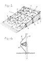
- Fig. 1 shows part of a gently sloping artificial rocky bottom.
- Fig. 2 shows a pond.
- Fig. 3 shows part of a wall with a rugged side.
- Fig. 4 shows a detail of a wall with a section for forming a crevice.
- Fig. 5 shows a detail for planting plants.
- In Fig. 1 the flexible sheeting material, for example a plastic sheet 1, is supported at various points by supports 2. In the illustration the heights of these
supports 2 are selected in such a way that a slope is obtained. Other surface shapes can, of course, also be obtained by selecting other lengths for thesupports 2. The plastic sheet can be placed between these supports in various shapes, depending on the desired appearance of the surface. In this case the plastic sheet is formed falling freely intofolds 3 and dips 4, so that an irregular surface resembling a rocky bottom is obtained. These folds can be at least partially glued or welded to each other, so that they have a permanent shape. - Below the plastic sheet is, for example,
sand 5, which provides a complete and solid support for the plastic sheet thus shaped. This means that the surface can take quite high local stresses. The impression of a rocky bottom can be further enhanced by providing the plastic sheet with the desired colours. - Fig. 2 shows another result which can be obtained with the process according to the invention. Here, a number of supports 7 are connected at the top by cross bars 8, in such a way that a space having a shape which corresponds approximately to the bank of a pond is produced. The plastic sheet is subsequently placed over this supporting structure and in the above-mentioned space assumes a basin shape 9. The depth of the basin can be determined by applying more or less plastic sheet. The basin thus formed can then be filled with
water 10, the pulling forces in the sheet being transferred by suitable fixing means to the supporting structure. - It is now very simple to make the pond merge into an artificial landscape by further shaping the sheet from the supporting structure as shown, for example, in Fig. 1. It is pointed out here that if the sheet for the pond part is only subjected to the uniform water load, the open space under that sheet part need not be filled up with sand for the purpose of supporting.
- Fig. 3 shows yet another object which can be made according to the invention. This object is in the form of a
wall 11. Thiswall 11 consists ofposts 12 fixed in the ground, to which shapedparts 13 pointing in the transverse direction of the wall are attached. These shapedparts 13 have the contour which is desired for the wall to be shaped, in the figure for example withcrevices 14. The shapedparts 13 need not all have the same contour; theplastic sheet 15 is flexible enough to absorb transition differences between the contours. Here again the sheet can have folds 16. - The wall can be provided on both sides with
crevices 14; the shapedparts 13 are provided on both sides with a contour which is suitable for this. - Finally, the wall is filled with, for example,
sand 17, by means of which a sturdy piece of work is obtained. Such a wall filled with sand also has good soundproofing. - The
crevices 14 can be used, for example, for planting plants. For this purpose, a suitable substrate such as earth is placed in thecrevices 14, in which the plants can take root. - Use can also be made here of the
section 18 shown in Fig. 4, which is fixed between theposts 12. Theplastic sheet 15 can be inserted between the flanges which face each other. Here again, plants and soil can be placed in the hollows formed by the plastic sheet. - Finally, yet another possibility for planting plants is shown in Fig. 5. Here, holes 20 are made in the
plastic sheet 19, so that the plants can be planted in the soil under theplastic sheet 19.
Claims (9)
Applications Claiming Priority (2)
| Application Number | Priority Date | Filing Date | Title |
|---|---|---|---|
| NL8700636A NL8700636A (en) | 1987-03-17 | 1987-03-17 | METHOD FOR GIVING GARDEN AND LANDSCAPE. |
| NL8700636 | 1987-03-17 |
Publications (2)
| Publication Number | Publication Date |
|---|---|
| EP0285202A1 true EP0285202A1 (en) | 1988-10-05 |
| EP0285202B1 EP0285202B1 (en) | 1991-06-12 |
Family
ID=19849723
Family Applications (1)
| Application Number | Title | Priority Date | Filing Date |
|---|---|---|---|
| EP19880200485 Expired - Lifetime EP0285202B1 (en) | 1987-03-17 | 1988-03-15 | Process for contouring garden and landscape |
Country Status (3)
| Country | Link |
|---|---|
| EP (1) | EP0285202B1 (en) |
| DE (1) | DE3863218D1 (en) |
| NL (1) | NL8700636A (en) |
Cited By (6)
| Publication number | Priority date | Publication date | Assignee | Title |
|---|---|---|---|---|
| FR2764474A1 (en) * | 1997-06-11 | 1998-12-18 | Pascal Peleszezak | Device for making floral decorations |
| WO2000000013A1 (en) * | 1998-06-30 | 2000-01-06 | Pascal Peleszezak | Device for making islands and floral designs |
| WO2011044556A3 (en) * | 2009-10-09 | 2011-09-09 | Pierce Jr Webster | Wave suppressor and sediment collection system |
| US8985896B2 (en) | 2009-10-09 | 2015-03-24 | Webster Pierce, Jr. | Water suppressor and sediment collection system for use in shallow and deeper water environments |
| US9885163B2 (en) | 2009-10-09 | 2018-02-06 | Webster Pierce, Jr. | Wave suppressor and sediment collection system |
| CN108434763A (en) * | 2018-03-27 | 2018-08-24 | 杭州也思文化传播有限公司 | Artistic performance device |
Citations (6)
| Publication number | Priority date | Publication date | Assignee | Title |
|---|---|---|---|---|
| US2113523A (en) * | 1937-08-18 | 1938-04-05 | White Stanley Hart | Vegetation-bearing architectonic structure and system |
| GB1417479A (en) * | 1973-09-25 | 1975-12-10 | Turzillo L A | Means and method for producing cementitious mat-like slope covers |
| FR2380378A1 (en) * | 1977-02-11 | 1978-09-08 | Hutchinson Mapa | Earthwork cladding material securing system - uses rigid component with open groove holding cladding anchored in ground |
| DE3409823A1 (en) * | 1983-03-17 | 1984-09-20 | Horst Dipl.-Phys. 8000 München Schramm | Process for producing integrated, lightweight solid constructions which aid redevelopment |
| WO1985003317A1 (en) * | 1984-01-26 | 1985-08-01 | Wolfgang Behrens | Dry lawn construction |
| FR2570422A1 (en) * | 1984-09-17 | 1986-03-21 | Scermi | LINING SUPPORT SYSTEM, PARTICULARLY FOR CONSTRUCTING A RETAINING BOWL FOR A LIQUID |
-
1987
- 1987-03-17 NL NL8700636A patent/NL8700636A/en not_active Application Discontinuation
-
1988
- 1988-03-15 EP EP19880200485 patent/EP0285202B1/en not_active Expired - Lifetime
- 1988-03-15 DE DE8888200485T patent/DE3863218D1/en not_active Expired - Fee Related
Patent Citations (6)
| Publication number | Priority date | Publication date | Assignee | Title |
|---|---|---|---|---|
| US2113523A (en) * | 1937-08-18 | 1938-04-05 | White Stanley Hart | Vegetation-bearing architectonic structure and system |
| GB1417479A (en) * | 1973-09-25 | 1975-12-10 | Turzillo L A | Means and method for producing cementitious mat-like slope covers |
| FR2380378A1 (en) * | 1977-02-11 | 1978-09-08 | Hutchinson Mapa | Earthwork cladding material securing system - uses rigid component with open groove holding cladding anchored in ground |
| DE3409823A1 (en) * | 1983-03-17 | 1984-09-20 | Horst Dipl.-Phys. 8000 München Schramm | Process for producing integrated, lightweight solid constructions which aid redevelopment |
| WO1985003317A1 (en) * | 1984-01-26 | 1985-08-01 | Wolfgang Behrens | Dry lawn construction |
| FR2570422A1 (en) * | 1984-09-17 | 1986-03-21 | Scermi | LINING SUPPORT SYSTEM, PARTICULARLY FOR CONSTRUCTING A RETAINING BOWL FOR A LIQUID |
Non-Patent Citations (1)
| Title |
|---|
| PATENT ABSTRACTS OF JAPAN, vol. 10, no. 381 (M-547)[2483], 19th December 1986, page 115 M 547; & JP-A-61 172 922 (NITTOKU KENSETSU K.K.) 04-08-1986 * |
Cited By (14)
| Publication number | Priority date | Publication date | Assignee | Title |
|---|---|---|---|---|
| FR2764474A1 (en) * | 1997-06-11 | 1998-12-18 | Pascal Peleszezak | Device for making floral decorations |
| WO2000000013A1 (en) * | 1998-06-30 | 2000-01-06 | Pascal Peleszezak | Device for making islands and floral designs |
| US9885163B2 (en) | 2009-10-09 | 2018-02-06 | Webster Pierce, Jr. | Wave suppressor and sediment collection system |
| US8985896B2 (en) | 2009-10-09 | 2015-03-24 | Webster Pierce, Jr. | Water suppressor and sediment collection system for use in shallow and deeper water environments |
| US9410299B2 (en) | 2009-10-09 | 2016-08-09 | Webster Pierce, Jr. | Wave suppressor and sediment collection system for use in shallow and deeper water environments |
| US9732491B2 (en) | 2009-10-09 | 2017-08-15 | Webster Pierce, Jr. | Water suppressor and sediment collection system for use in shallow and deeper water environments |
| WO2011044556A3 (en) * | 2009-10-09 | 2011-09-09 | Pierce Jr Webster | Wave suppressor and sediment collection system |
| US10060089B2 (en) | 2009-10-09 | 2018-08-28 | Webster Pierce, Jr. | Wave suppressor and sediment collection system for use in shallow and deeper water environments |
| US10221534B2 (en) | 2009-10-09 | 2019-03-05 | Webster Pierce, Jr. | Wave suppressor and sediment collection system |
| US10450712B2 (en) | 2009-10-09 | 2019-10-22 | Webster Pierce, Jr. | Wave suppressor and sediment collection system for use in shallow and deeper water environments |
| US10669684B2 (en) | 2009-10-09 | 2020-06-02 | Webster Pierce, Jr. | Wave suppressor and sediment collection system |
| US10787779B2 (en) | 2009-10-09 | 2020-09-29 | Webster Pierce, Jr. | Wave suppressor and sediment collection system for use in shallow and deeper water environments |
| US11326317B2 (en) | 2009-10-09 | 2022-05-10 | Webster Pierce, Jr. | Wave suppressor and sediment collection system for use in shallow and deeper water environments |
| CN108434763A (en) * | 2018-03-27 | 2018-08-24 | 杭州也思文化传播有限公司 | Artistic performance device |
Also Published As
| Publication number | Publication date |
|---|---|
| EP0285202B1 (en) | 1991-06-12 |
| NL8700636A (en) | 1988-10-17 |
| DE3863218D1 (en) | 1991-07-18 |
Similar Documents
| Publication | Publication Date | Title |
|---|---|---|
| AU641150B2 (en) | Improvements relating to building and shoring blocks | |
| CN106088109B (en) | Discarded pit slope ecological recovery covers green construction method | |
| CN109403267A (en) | A kind of cast-in-place green concrete of nutrition hole type and its construction method | |
| CN105625443A (en) | High-steep soil nail grass planting slope protection structure system and construction method thereof | |
| CN110306491A (en) | A kind of river channel ecology bank protection construction technique | |
| CN112144552A (en) | Damaged mountain ecological vegetation restoration structure, implementation method and application thereof | |
| EP0285202A1 (en) | Process for contouring garden and landscape | |
| KR100922466B1 (en) | Stone Net Bag and its construction Method | |
| US6494009B1 (en) | Green concrete retaining wall and method for constructing the same | |
| CN209277095U (en) | A kind of cast-in-place counterfort virescence concrete structure | |
| CN114457841B (en) | Concrete retaining wall hard landscape ecological softening structure and construction method thereof | |
| CN2789360Y (en) | Green vegetation building | |
| CN215105078U (en) | Ecological restoration revetment | |
| CN112359850B (en) | Masonry protection structure of road engineering and construction method thereof | |
| CN114635432A (en) | Construction method of composite ecological slope protection of foundation pit | |
| CN115142443A (en) | Greening protection process for high and steep slope and device thereof | |
| JPS61137922A (en) | Sheathing work for slope | |
| KR102317257B1 (en) | artificial mountain with cave | |
| KR200413303Y1 (en) | Stone stacked wall structure using steel beam | |
| KR100466007B1 (en) | Seed bed Gabion | |
| KR19990046526A (en) | A structure for establing a slope and execution method using it | |
| JPS5820338B2 (en) | Slope stabilization method | |
| CN220580022U (en) | Lattice type slope protection structure | |
| CN217580226U (en) | Collect drainage, reinforcement and ecological afforestation in side slope ecological protection structure of an organic whole | |
| CN212451059U (en) | Water purification ecological revetment structure of multistage wetland |
Legal Events
| Date | Code | Title | Description |
|---|---|---|---|
| PUAI | Public reference made under article 153(3) epc to a published international application that has entered the european phase |
Free format text: ORIGINAL CODE: 0009012 |
|
| AK | Designated contracting states |
Kind code of ref document: A1 Designated state(s): BE DE FR GB LU NL |
|
| 17P | Request for examination filed |
Effective date: 19890310 |
|
| 17Q | First examination report despatched |
Effective date: 19891227 |
|
| GRAA | (expected) grant |
Free format text: ORIGINAL CODE: 0009210 |
|
| AK | Designated contracting states |
Kind code of ref document: B1 Designated state(s): BE DE FR GB LU NL |
|
| ET | Fr: translation filed | ||
| REF | Corresponds to: |
Ref document number: 3863218 Country of ref document: DE Date of ref document: 19910718 |
|
| PLBE | No opposition filed within time limit |
Free format text: ORIGINAL CODE: 0009261 |
|
| STAA | Information on the status of an ep patent application or granted ep patent |
Free format text: STATUS: NO OPPOSITION FILED WITHIN TIME LIMIT |
|
| 26N | No opposition filed | ||
| PGFP | Annual fee paid to national office [announced via postgrant information from national office to epo] |
Ref country code: GB Payment date: 19940311 Year of fee payment: 7 |
|
| PGFP | Annual fee paid to national office [announced via postgrant information from national office to epo] |
Ref country code: DE Payment date: 19940323 Year of fee payment: 7 |
|
| PGFP | Annual fee paid to national office [announced via postgrant information from national office to epo] |
Ref country code: FR Payment date: 19940324 Year of fee payment: 7 |
|
| PGFP | Annual fee paid to national office [announced via postgrant information from national office to epo] |
Ref country code: NL Payment date: 19940331 Year of fee payment: 7 Ref country code: LU Payment date: 19940331 Year of fee payment: 7 |
|
| PGFP | Annual fee paid to national office [announced via postgrant information from national office to epo] |
Ref country code: BE Payment date: 19940427 Year of fee payment: 7 |
|
| EPTA | Lu: last paid annual fee | ||
| PG25 | Lapsed in a contracting state [announced via postgrant information from national office to epo] |
Ref country code: LU Free format text: LAPSE BECAUSE OF NON-PAYMENT OF DUE FEES Effective date: 19950315 Ref country code: GB Effective date: 19950315 |
|
| PG25 | Lapsed in a contracting state [announced via postgrant information from national office to epo] |
Ref country code: BE Effective date: 19950331 |
|
| BERE | Be: lapsed |
Owner name: POLYDAK B.V. Effective date: 19950331 |
|
| PG25 | Lapsed in a contracting state [announced via postgrant information from national office to epo] |
Ref country code: NL Effective date: 19951001 |
|
| GBPC | Gb: european patent ceased through non-payment of renewal fee |
Effective date: 19950315 |
|
| PG25 | Lapsed in a contracting state [announced via postgrant information from national office to epo] |
Ref country code: FR Free format text: LAPSE BECAUSE OF NON-PAYMENT OF DUE FEES Effective date: 19951130 |
|
| NLV4 | Nl: lapsed or anulled due to non-payment of the annual fee |
Effective date: 19951001 |
|
| PG25 | Lapsed in a contracting state [announced via postgrant information from national office to epo] |
Ref country code: DE Effective date: 19951201 |
|
| REG | Reference to a national code |
Ref country code: FR Ref legal event code: ST |